EP0736792A2 - Bildschirmgerät - Google Patents
Bildschirmgerät Download PDFInfo
- Publication number
- EP0736792A2 EP0736792A2 EP96104324A EP96104324A EP0736792A2 EP 0736792 A2 EP0736792 A2 EP 0736792A2 EP 96104324 A EP96104324 A EP 96104324A EP 96104324 A EP96104324 A EP 96104324A EP 0736792 A2 EP0736792 A2 EP 0736792A2
- Authority
- EP
- European Patent Office
- Prior art keywords
- display device
- light
- lamp
- display
- additional
- Prior art date
- Legal status (The legal status is an assumption and is not a legal conclusion. Google has not performed a legal analysis and makes no representation as to the accuracy of the status listed.)
- Granted
Links
Images
Classifications
-
- G—PHYSICS
- G02—OPTICS
- G02F—OPTICAL DEVICES OR ARRANGEMENTS FOR THE CONTROL OF LIGHT BY MODIFICATION OF THE OPTICAL PROPERTIES OF THE MEDIA OF THE ELEMENTS INVOLVED THEREIN; NON-LINEAR OPTICS; FREQUENCY-CHANGING OF LIGHT; OPTICAL LOGIC ELEMENTS; OPTICAL ANALOGUE/DIGITAL CONVERTERS
- G02F1/00—Devices or arrangements for the control of the intensity, colour, phase, polarisation or direction of light arriving from an independent light source, e.g. switching, gating or modulating; Non-linear optics
- G02F1/01—Devices or arrangements for the control of the intensity, colour, phase, polarisation or direction of light arriving from an independent light source, e.g. switching, gating or modulating; Non-linear optics for the control of the intensity, phase, polarisation or colour
- G02F1/13—Devices or arrangements for the control of the intensity, colour, phase, polarisation or direction of light arriving from an independent light source, e.g. switching, gating or modulating; Non-linear optics for the control of the intensity, phase, polarisation or colour based on liquid crystals, e.g. single liquid crystal display cells
- G02F1/133—Constructional arrangements; Operation of liquid crystal cells; Circuit arrangements
- G02F1/1333—Constructional arrangements; Manufacturing methods
- G02F1/1335—Structural association of cells with optical devices, e.g. polarisers or reflectors
- G02F1/1336—Illuminating devices
-
- G—PHYSICS
- G02—OPTICS
- G02B—OPTICAL ELEMENTS, SYSTEMS OR APPARATUS
- G02B6/00—Light guides; Structural details of arrangements comprising light guides and other optical elements, e.g. couplings
- G02B6/0001—Light guides; Structural details of arrangements comprising light guides and other optical elements, e.g. couplings specially adapted for lighting devices or systems
Definitions
- the invention relates to a screen device with a display panel that can be illuminated by at least one lamp.
- Such screen devices are generally known and are often used as notebooks, watches or cell phones.
- the lamp is integrated in the display device and connected to the power supply, which is present anyway.
- the lamp is either located behind the display panel and illuminates it, or it is arranged under a panel on the edge of the display panel and illuminates it from the side.
- efforts are made in both cases to place the lamp as close as possible to the display panel.
- this has the consequence that the display panel and the display device are heated by the heat emitted by the lamp.
- Another disadvantage is that the lamp increases the weight and volume and in In the case of a portable screen device the user must carry it, even if he does not need it.
- the power supply designed as a battery can have only a limited size. This in turn also limits the possible luminance that the lamp can produce.
- the invention is based on the problem of designing a display device of the type mentioned at the outset in such a way that lighting with high luminance is made possible, heating of the display device by the lamp being kept as low as possible without reflections occurring and without the construction volume and / or the weight of the display device increases.
- At least one lamp is arranged in an additional device and in the display device there is a means for transmitting light to the display panel.
- the lighting device and the power source supplying it are arranged in a stationary manner outside the display device, they can be of large design and enable high power consumption, which in turn allows high-luminance lighting.
- the monitor can be designed so that the additional device is attached to an edge of the display panel.
- its lighting is more convenient if the screen device has at least one light inlet on its rear, behind which the lamp of the additional device is arranged, and if the display panel can be illuminated.
- a particular advantage of this development of the invention is that the indirect illumination of the display panel avoids unwanted reflections. Furthermore, a particularly uniform illumination can be achieved with fluoroscopy.
- mirrors In order to transmit the light from the lamp evenly to the display panel, mirrors can be provided. However, these mirrors increase the design effort and require a large volume.
- the construction is particularly simple if the means in the display device for transmitting light to the display panel is a light guide.
- Such light guides can be produced inexpensively and are easy to install. Their optical properties allow the display field to be illuminated particularly evenly. The heat emitted by the lamp is passed on through the material of the light guide is prevented. Materials commonly used for light guides have a high transmittance for visible light and a low one for heat radiation.
- the light can be guided particularly easily to required points if a light guide is present in the additional device.
- An advantageous development of the invention is that corresponding light coupling surfaces are arranged on the back of the monitor with light coupling surfaces of the additional device. In this way an optimal distribution of the light is achieved.
- the transition of the light from the additional device to the display device is particularly advantageous if the light coupling-out surface has a convex shape and the light coupling-in surface has a concave shape. These shapes are easy to clean and guarantee very good light transmission. Furthermore, the display device is centered independently on the additional device, which benefits increased ease of use. A further centering or guidance for the display device is therefore not necessary. Conversely, of course, the light decoupling surface can also have a concave shape and the light coupling surface can have a convex shape.
- the additional device is a holder that receives the display device and is installed in a fixed position in the motor vehicle.
- the additional device can thus remain in one place in the motor vehicle, while the display device is portable and with its own power supply (accumulator) - although it can still be used without its own lighting.
- the weight of the mobile display device is kept low and despite comparatively small batteries for the internal power supply, long operational readiness is ensured, since energy consumption by lighting during mobile operation is completely avoided.
- the display device becomes more comfortable if, according to a development of the invention, a switch that activates the lamp and is activated by the display device is present in the additional device.
- the display device if, in addition to the internal supply to the display device, it has an external, independent power supply. Particularly in connection with the design of the additional device as a fixed holder, this development of the invention offers a more secure power supply for the lamp and display device. Since the power supply present in the display device is not used for lighting purposes, its capacity is protected and its service life is also increased.
- an accumulator arranged in the display device can be connected to the external power supply. The battery can then be charged.
- the display panel is always clearly visible when the lamp is dimmable, in particular depending on the ambient light.
- a particularly varied area of application of the invention is that the display device is designed to display information required in a motor vehicle.
- the additional device can also be used as a lighting unit without the screen device, e.g. be used for reading cards.
- the lamp in the additional device can be used for signal transmission if the lamp can be influenced by the display device. This makes it possible to e.g. to have flashes triggered by the display device in the event of pre-programmed events.
- the invention permits numerous embodiments. To further clarify its basic principle, a cross section through an illumination device according to the invention is shown in the drawing and is described below.
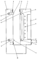
- the drawing shows a monitor 1, which is inserted into an additional device 2.
- lamps 3 are arranged, which are connected to the display device 1 via light guides 4.
- light guides 4 which transport the light 5 to a display field 6, which is expediently designed as an energy-saving liquid crystal display.
- the transition of the light 5 from the additional device 2 to the display device 1 takes place via light decoupling surfaces 7 on the additional device 2 and light coupling surfaces 8 on the display device 1.
- the light decoupling surface 7 has a convex shape which is matched to a concave shape of the light coupling surface 8. This shape centers the screen device 1 on the additional device 2. This always ensures optimal transmission of the light 5.
- An external power supply of the display device 1 takes place via contact rails 9 after it has been inserted into the additional device 2.
- a switch 10 can be seen which switches on the lamps 3 as soon as the display device 1 is inserted into the additional device 2.
- An input field 11 with keys 12 is located on the display device 1 below the display field 6.
- the lamps 3 can be controlled separately and have different colors. With this e.g. Depending on the current operating mode of the display device 1, a different basic color of the display field 6 can be achieved.
Landscapes
- Physics & Mathematics (AREA)
- General Physics & Mathematics (AREA)
- Optics & Photonics (AREA)
- Nonlinear Science (AREA)
- Mathematical Physics (AREA)
- Chemical & Material Sciences (AREA)
- Crystallography & Structural Chemistry (AREA)
- Devices For Indicating Variable Information By Combining Individual Elements (AREA)
- Illuminated Signs And Luminous Advertising (AREA)
- Non-Portable Lighting Devices Or Systems Thereof (AREA)
Abstract
Description
- Die Erfindung betrifft ein Bildschirmgerät mit einem von mindestens einer Lampe beleuchtbaren Anzeigefeld.
- Solche Bildschirmgeräte sind allgemein bekannt und werden häufig als Notebooks, Uhren oder Handys eingesetzt. Hierbei ist die Lampe in das Bildschirmgerät integriert und an die ohnehin vorhandene Stromversorgung angeschlossen. Dabei befindet sich die Lampe entweder hinter dem Anzeigefeld und durchleuchtet dieses, oder sie ist unter einer Verkleidung am Rand des Anzeigefeldes angeordnet und beleuchtet dieses von der Seite. Um die Abmessungen des Bildschirmgerätes in Grenzen zu halten, ist man in beiden Fällen bestrebt, die Lampe so nah wie möglich an das Anzeigefeld anzuordnen. Das hat jedoch zur Folge, daß durch die Wärmeabgabe der Lampe das Anzeigefeld und auch das Bildschirmgerät aufgeheizt werden. Von Nachteil ist auch, daß die Lampe das Gewicht und das Volumen erhöht und im Falle eines tragbaren Bildschirmgerätes vom Benutzer mitgeführt werden muß, auch wenn er sie nicht benötigt.
- Da das Gewicht und das Volumen des Bildschirmgerätes ein bestimmtes vertretbares Maß nicht überschreiten darf, kann die als Batterie ausgebildete Stromversorgung nur begrenzte Größe haben. Dies führt wiederum auch zu einer Begrenzung der möglichen Leuchtdichte, die die Lampe erzeugen kann.
- Derartige Bildschirmgeräte unterliegen als mobile Einheiten auch erheblichen Stoßbelastungen, die häufig zu einem frühzeitigen Defekt der Lampen führen.
- Wenn man die durch eine Lampe auftretende Erwärmung des Bildschirmgerätes verringern will, kann man auch eine Lampe nach Art einer Leselampe zur Beleuchtung des Anzeigefeldes von oben vorsehen. Das erhöht jedoch ebenfalls das Gewicht und das Volumen des Bildschirmgerätes und führt zu unerwünschten Reflexionen.
- Der Erfindung liegt das Problem zugrunde, ein Bildschirmgerät der eingangs genannten Art so zu gestalten, daß eine Beleuchtung mit hoher Leuchtdichte ermöglicht wird, wobei eine Aufheizung des Bildschirmgerätes durch die Lampe so gering wie möglich gehalten wird, ohne daß Reflexionen auftreten und ohne daß das Bauvolumen und/oder das Gewicht des Bildschirmgerätes zunimmt.
- Dieses Problem wird erfindungsgemäß dadurch gelöst, daß mindestens eine Lampe in einem Zusatzgerät angeordnet ist und im Bildschirmgerät ein Mittel zur Übertragung von Licht auf das Anzeigefeld vorhanden ist.
- Mit der baulichen Trennung von Bildschirmgerät und die Lampe aufweisendem Zusatzgerät wird eine deutliche Verringerung der Wärmebelastung des Anzeigefeldes erzielt, da die Wärme erzeugenden Teile sich außerhalb des Bildschirmgerätes befinden. Im Falle eines tragbaren Bildschirmgerätes verringert sich dessen Gewicht und Volumen, da dieses keine Beleuchtung enthält, dennoch aber in Verbindung mit dem Zusatzgerät eine Beleuchtung möglich ist.
- Da die Beleuchtungseinrichtung und die sie versorgende Stromquelle stationär außerhalb des Bildschirmgerätes angeordnet sind, können sie groß ausgebildet sein und einen hohen Stromverbrauch ermöglichen, was wiederum eine Beleuchtung hoher Leuchtdichte gestattet.
- Das Bildschirmgerät kann konstruktiv so gestaltet werden, daß das Zusatzgerät an einem Rand des Anzeigefeldes befestigt wird. Dessen Beleuchtung gestaltet sich jedoch komfortabler, wenn das Bildschirmgerät an seiner Rückseite zumindest einen Lichteinlaß hat, hinter den die Lampe des Zusatzgerätes angeordnet ist, und wenn das Anzeigefeld durchleuchtbar ist. Ein besonderer Vorteil dieser Weiterbildung der Erfindung liegt darin, daß die indirekte Beleuchtung des Anzeigefeldes unerwünschte Reflexionen vermeidet. Weiterhin ist mit einer Durchleuchtung eine besonders gleichmäßige Ausleuchtung zu erzielen.
- Um das Licht von der Lampe gleichmäßig auf das Anzeigefeld zu übertragen, können Spiegel vorgesehen sein. Diese Spiegel erhöhen jedoch den konstruktiven Aufwand und benötigen ein großes Volumen. Der konstruktive Aufbau gestaltet sich dann besonders einfach, wenn das Mittel im Bildschirmgerät zur Übertragung von Licht auf das Anzeigefeld ein Lichtleiter ist. Derartige Lichtleiter lassen sich kostengünstig herstellen und sind einfach zu verlegen. Deren optische Eigenschaften erlauben die besonders gleichmäßige Ausleuchtung des Anzeigefeldes. Eine Weiterleitung der von der Lampe abgegebenen Wärme wird durch das Material des Lichtleiters unterbunden. Üblicherweise für Lichtleiter verwendete Materialien weisen einen hohen Transmissionsgrad für sichtbares Licht und einen im Vergleich dazu niedrigen für Wärmestrahlung auf.
- Auch im Zusatzgerät läßt sich das Licht besonders leicht zu benötigten Punkten leiten, wenn im Zusatzgerät ein Lichtleiter vorhanden ist.
- Eine vorteilhafte Weiterbildung der Erfindung besteht darin, daß auf der Rückseite des Bildschirmgerätes mit Lichtauskoppelungsflächen des Zusatzgerätes korrespondierende Lichteinkoppelungsflächen angeordnet sind. Auf diese Weise wird eine optimale Verteilung des Lichtes erreicht.
- Besonders vorteilhaft ist der Übergang des Lichtes von dem Zusatzgerät zu dem Bildschirmgerät, wenn die Lichtauskoppelungsfläche eine konvexe Form und die Lichteinkoppelungsfläche eine konkave Form aufweist. Diese Formen sind leicht zu reinigen und garantieren eine sehr gute Lichtleitung. Weiterhin zentriert sich das Bildschirmgerät selbständig auf dem Zusatzgerät, was einem erhöhten Bedienkomfort zugute kommt. Eine weitere Zentrierung oder Führung für das Bildschirmgerät ist damit nicht erforderlich. Natürlich kann in Umkehrung auch die Lichtauskoppelungsfläche eine konkave und die Lichteinkoppelungsfläche eine konvexe Form besitzen.
- Für ein tragbares Bildschirmgerät, wie z.B. ein Navigationsgerät für ein Kraftfahrzeug, ist es von Vorteil, wenn das Zusatzgerät eine das Bildschirmgerät aufnehmende, im Kraftfahrzeug ortsfest installierte Halterung ist. Damit kann das Zusatzgerät an einem Ort im Kraftfahrzeug bleiben, während das Bildschirmgerät transportabel und mit seiner eigenen Stromversorgung (Akkumulator) - wenngleich auch ohne eigene Beleuchtung - einsetzbar bleibt.
- Auf diese Weise wird das Gewicht des mobilen Bildschirmgerätes niedrig gehalten und trotz vergleichsweise kleiner Akkumulatoren für die interne Stromversorgung eine lange Betriebsbereitschaft gesichert, da ein Energieverbrauch durch eine Beleuchtung während des mobilen Betriebs vollständig vermieden wird.
- Das Bildschirmgerät wird komfortabler, wenn gemäß einer Weiterbildung der Erfindung in dem Zusatzgerät ein von dem Bildschirmgerät gesteuerter, die Lampe aktivierender Schalter vorhanden ist.
- Für das Bildschirmgerät ist es von Vorteil, wenn es zusätzlich zur bildschirmgerätinternen Stromversorgung eine davon externe unabhängige Stromversorgung hat. Besonders in Verbindung mit der Ausbildung des Zusatzgerätes als ortsfeste Halterung bietet diese Weiterbildung der Erfindung eine sicherere Stromversorgung für Lampe und Bildschirmgerät. Da die in dem Bildschirmgerät vorhandene Stromversorgung nicht für Beleuchtungszwecke verwendet wird, wird deren Kapazität geschont und es erhöht sich damit auch deren Lebensdauer.
- Von großem Vorteil ist es, wenn ein im Bildschirmgerät angeordneter Akkumulator mit der externen Stromversorgung verbindbar ist. Damit kann dann der Akkumulator aufgeladen werden.
- Das Anzeigefeld ist immer gut zu erkennen, wenn die Lampe dimmbar, insbesondere umgebungslichtabhängig dimmbar ist.
- Ein besonders vielfältiges Einsatzgebiet der Erfindung liegt darin, daß das Bildschirmgerät zur Anzeige von in einem KFZ benötigten Informationen ausgebildet ist.
- Insbesondere im KFZ kann das Zusatzgerät auch ohne das Bildschirmgerät als Beleuchtungseinheit z.B. zum Kartenlesen benutzt werden.
- Die Lampe im Zusatzgerät kann zu einer Signalübertragung benutzt werden, wenn die Lampe von dem Bildschirmgerät beeinflußbar ist. Dadurch ist es möglich, die Lampe z.B. bei vorprogrammierten Ereignissen im Bildschirmgerät von diesem angesteuert blinken zu lassen.
- Die Erfindung läßt zahlreiche Ausführungsformen zu. Zur weiteren Verdeutlichung ihres Grundprinzips ist in der Zeichnung ein Querschnitt durch eine erfindungsgemäße Beleuchtungseinrichtung dargestellt und wird nachfolgend beschrieben.
- Die Zeichnung zeigt ein Bildschirmgerät 1, welches in ein Zusatzgerät 2 eingeschoben wird. In dem Zusatzgerät 2 sind Lampen 3 angeordnet, welche über Lichtleiter 4 mit dem Bildschirmgerät 1 verbunden sind. Im Bildschirmgerät 1 sind ebenfalls Lichtleiter 4 vorhanden, die das Licht 5 zu einem Anzeigefeld 6 transportieren, welches zweckmäßig als stromsparendes Flüssigkristall-Display ausgebildet ist. Der Übergang des Lichtes 5 von dem Zusatzgerät 2 zu dem Bildschirmgerät 1 erfolgt über Lichtauskoppelungsflächen 7 am Zusatzgerät 2 und Lichteinkoppelungsflächen 8 am Bildschirmgerät 1. Die Lichtauskoppelungsfläche 7 weist eine konvexe Form auf, die auf eine konkave Form der Lichteinkoppelungsfläche 8 abgestimmt ist. Diese Formgebung zentriert das Bildschirmgerät 1 auf dem Zusatzgerät 2. Damit ist immer eine optimale Weiterleitung des Lichtes 5 gewährleistet.
- Eine externe Stromversorgung des Bildschirmgerätes 1 erfolgt über Kontaktschienen 9 nach dessen Einschieben in das Zusatzgerät 2. Ein nicht dargestellter Akkumulator im Bildschirmgerät 1, der dessen Betrieb im mobilen Einsatz unabhängig von der externen Stromversorgung gestattet, wird zeitgleich über die Kontaktschienen 9 aufgeladen. Dies hat den großen Vorteil, daß das Bildschirmgerät 1 für den mobilen Einsatz stets mit der vollen Kapazität seiner internen Stromversorgung zur Verfügung steht.
- An der dem Bildschirmgerät 1 zugewandten Seite des Zusatzgerätes 2 erkennt man einen Schalter 10, der die Lampen 3 anschaltet, sobald das Bildschirmgerät 1 in das Zusatzgerät 2 eingeschoben wird.
- Auf dem Bildschirmgerät 1 befindet sich unterhalb des Anzeigefeldes 6 ein Eingabefeld 11 mit Tasten 12.
- Die Lampen 3 können separat ansteuerbar sein und unterschiedliche Farben besitzen. Damit kann z.B. je nach dem momentanen Betriebsmodus des Bildschirmgerätes 1 eine unterschiedliche Grundfarbe des Anzeigefeldes 6 erreicht werden.
Claims (13)
- Bildschirmgerät mit einem von mindestens einer Lampe beleuchtbaren Anzeigefeld, dadurch gekennzeichnet, daß mindestens eine Lampe (3) in einem Zusatzgerät (2) angeordnet ist und im Bildschirmgerät (1) ein Mittel zur Übertragung von Licht (5) auf das Anzeigefeld (6) vorhanden ist.
- Bildschirmgerät nach Anspruch 1, dadurch gekennzeichnet, daß das Bildschirmgerät (1) an seiner Rückseite und/oder seinem Seitenbereich zumindest einen Lichteinlaß (Lichteinkoppelungsfläche 8) hat, hinter dem die Lampe (3) des Zusatzgerätes (2) angeordnet ist, und das Anzeigefeld (6) durchleuchtbar ist.
- Bildschirmgerät nach Anspruch 1 oder 2, dadurch gekennzeichnet, daß das Mittel im Bildschirmgerät (1) zur Übertragung von Licht (5) auf das Anzeigefeld (6) ein Lichtleiter (4) ist.
- Bildschirmgerät nach zumindest einem der vorhergehenden Ansprüche, dadurch gekennzeichnet, daß im Zusatzgerät (2) ein Lichtleiter (4) vorhanden ist.
- Bildschirmgerät nach zumindest einem der vorhergehenden Ansprüche, dadurch gekennzeichnet, daß auf der Rückseite des Bildschirmgerätes (1) mit Lichtauskoppelungsflächen (7) des Zusatzgerätes (2) korrespondierende Lichteinkoppelungsflächen (8) angeordnet sind.
- Bildschirmgerät nach zumindest einem der vorhergehenden Ansprüche, dadurch gekennzeichnet, daß die Lichtauskoppelungsfläche (7) eine konvexe bzw. konkave Form und die Lichteinkoppelungsfläche (8) eine konkave bzw. konvexe Form aufweist.
- Bildschirmgerät nach zumindest einem der vorhergehenden Ansprüche, dadurch gekennzeichnet, daß das Zusatzgerät (2) eine das Bildschirmgerät (1) aufnehmende ortsfeste Halterung ist.
- Bildschirmgerät nach zumindest einem der vorhergehenden Ansprüche, dadurch gekennzeichnet, daß in dem Zusatzgerät (2) ein von dem Bildschirmgerät (1) gesteuerter, die Lampe (3) aktivierender Schalter (10) vorhanden ist.
- Bildschirmgerät nach zumindest einem der vorhergehenden Ansprüche, dadurch gekennzeichnet, daß das Zusatzgerät (2) eine vom Bildschirmgerät (1) unabhängige Stromversorgung hat.
- Bildschirmgerät nach zumindest einem der vorhergehenden Ansprüche, dadurch gekennzeichnet, daß ein im Bildschirmgerät (1) angeordneter Akkumulator mit der externen Stromversorgung verbindbar ist.
- Bildschirmgerät nach zumindest einem der vorhergehenden Ansprüche, dadurch gekennzeichnet, daß die Lampe (3) umgebungslichtabhängig dimmbar ist.
- Bildschirmgerät nach zumindest einem der vorhergehenden Ansprüche, dadurch gekennzeichnet, daß das Bildschirmgerät (1) zur Anzeige von in einem KFZ benötigten Informationen ausgebildet ist.
- Bildschirmgerät nach zumindest einem der vorhergehenden Ansprüche, dadurch gekennzeichnet, daß die Lampe (3) von dem Bildschirmgerät (1) beeinflußbar ist.
Applications Claiming Priority (2)
| Application Number | Priority Date | Filing Date | Title |
|---|---|---|---|
| DE19512079A DE19512079A1 (de) | 1995-04-03 | 1995-04-03 | Bildschirmgerät |
| DE19512079 | 1995-04-03 |
Publications (3)
| Publication Number | Publication Date |
|---|---|
| EP0736792A2 true EP0736792A2 (de) | 1996-10-09 |
| EP0736792A3 EP0736792A3 (de) | 1999-12-15 |
| EP0736792B1 EP0736792B1 (de) | 2003-06-18 |
Family
ID=7758421
Family Applications (1)
| Application Number | Title | Priority Date | Filing Date |
|---|---|---|---|
| EP96104324A Expired - Lifetime EP0736792B1 (de) | 1995-04-03 | 1996-03-19 | Bildschirmgerät |
Country Status (5)
| Country | Link |
|---|---|
| US (1) | US6100869A (de) |
| EP (1) | EP0736792B1 (de) |
| JP (1) | JPH08314400A (de) |
| AT (1) | ATE243304T1 (de) |
| DE (2) | DE19512079A1 (de) |
Families Citing this family (6)
| Publication number | Priority date | Publication date | Assignee | Title |
|---|---|---|---|---|
| JP4883543B2 (ja) * | 2000-01-14 | 2012-02-22 | 九州日立マクセル株式会社 | 発光表示装置 |
| TWI243940B (en) * | 2000-11-01 | 2005-11-21 | Au Optronics Corp | Housing for flat panel display and method for assembly the same |
| KR101009676B1 (ko) | 2003-12-30 | 2011-01-19 | 엘지디스플레이 주식회사 | 착탈식 액정표시장치 |
| EP1571719A1 (de) * | 2004-03-05 | 2005-09-07 | Siemens Aktiengesellschaft | Wiederaufladbare Batterie und elektronisches Gerät |
| US7206483B1 (en) | 2005-11-01 | 2007-04-17 | Hewlett-Packard Development Company, L.P. | Method of forming a plurality of optical waveguide bundles |
| TWI649592B (zh) * | 2018-01-15 | 2019-02-01 | 友達光電股份有限公司 | 顯示裝置 |
Family Cites Families (25)
| Publication number | Priority date | Publication date | Assignee | Title |
|---|---|---|---|---|
| US1219731A (en) * | 1915-06-01 | 1917-03-20 | Jersey City Printing Company | Plural-image device. |
| US2261571A (en) * | 1939-07-01 | 1941-11-04 | Harold C Smith | Vehicle signal |
| FR1409010A (fr) * | 1964-08-18 | 1965-08-20 | Pertint Ltd | Perfectionnement à des enseignes lumineuses publicitaires ou analogues |
| US3573814A (en) * | 1968-06-07 | 1971-04-06 | Symbolic Displays Inc | Lighted display units |
| FR2235631A5 (en) * | 1973-06-29 | 1975-01-24 | Forms | Display lighting for publicity or domestic use - designs are engraved on polished translucent illuminated plate |
| US3957351A (en) * | 1974-09-16 | 1976-05-18 | Rockwell International Corporation | Backlighted display apparatus |
| US4043636A (en) * | 1974-12-23 | 1977-08-23 | Intel Corporation | Illumination-panel for liquid crystal display of similar device |
| US3994564A (en) * | 1975-03-31 | 1976-11-30 | Hughes Aircraft Company | Light pipe reflector for use in liquid crystal or other display |
| DE2902745A1 (de) * | 1979-01-25 | 1980-08-07 | Vdo Schindling | Ueber lichtleiter beleuchtete kraftfahrzeuginstrumente |
| US4487481A (en) * | 1980-03-24 | 1984-12-11 | Epson Corporation | Backlighted liquid crystal display |
| DE3511839A1 (de) * | 1985-03-30 | 1986-10-02 | Braun Ag, 6000 Frankfurt | Lichtleiter zum beleuchten von geraeteanzeigen |
| US4945350A (en) * | 1985-07-09 | 1990-07-31 | Mitsubishi Denki Kabushiki Kaisha | Liquid crystal display unit |
| JPS62125329A (ja) * | 1985-11-27 | 1987-06-06 | Hosiden Electronics Co Ltd | 透過形表示装置 |
| US4791745A (en) * | 1987-03-20 | 1988-12-20 | Pohn Mac R | Black light display system |
| DE8711933U1 (de) * | 1987-09-03 | 1987-10-29 | Ta Triumph-Adler Ag, 8500 Nuernberg | Vorrichtung zum Beleuchten von durchscheinenden Anzeigefeldern |
| JP2766347B2 (ja) * | 1989-10-31 | 1998-06-18 | 株式会社東芝 | 小型電子機器 |
| US5075824A (en) * | 1990-04-30 | 1991-12-24 | Motorola, Inc. | LCD/light wedge module |
| US5130907A (en) * | 1990-07-11 | 1992-07-14 | Curtis Manufacturing Company, Inc. | Light apparatus for use with a compact computer video screen |
| US5130097A (en) * | 1990-07-31 | 1992-07-14 | The United States Of America As Represented By The Department Of Energy | Apparatus for hot-gas desulfurization of fuel gases |
| JP2890823B2 (ja) * | 1990-11-21 | 1999-05-17 | 株式会社デンソー | 表示盤 |
| US5406268A (en) * | 1991-06-12 | 1995-04-11 | Iqv Corporation | Portable microcomputer with power-sparing system of illuminated indicators |
| JPH05197447A (ja) * | 1991-10-14 | 1993-08-06 | Hitachi Ltd | 情報処理装置 |
| US5580146A (en) * | 1992-11-20 | 1996-12-03 | Projectavision, Inc. | Rear screen video display system |
| JPH07104234A (ja) * | 1993-09-30 | 1995-04-21 | Sanyo Electric Co Ltd | 液晶表示装置 |
| US5745340A (en) * | 1994-12-19 | 1998-04-28 | Landau; Jennifer | Separable display of computer generated information |
-
1995
- 1995-04-03 DE DE19512079A patent/DE19512079A1/de not_active Ceased
-
1996
- 1996-03-19 AT AT96104324T patent/ATE243304T1/de not_active IP Right Cessation
- 1996-03-19 EP EP96104324A patent/EP0736792B1/de not_active Expired - Lifetime
- 1996-03-19 DE DE59610534T patent/DE59610534D1/de not_active Expired - Fee Related
- 1996-04-03 US US08/630,429 patent/US6100869A/en not_active Expired - Fee Related
- 1996-04-03 JP JP8081472A patent/JPH08314400A/ja active Pending
Also Published As
| Publication number | Publication date |
|---|---|
| EP0736792B1 (de) | 2003-06-18 |
| ATE243304T1 (de) | 2003-07-15 |
| EP0736792A3 (de) | 1999-12-15 |
| JPH08314400A (ja) | 1996-11-29 |
| DE19512079A1 (de) | 1996-10-10 |
| DE59610534D1 (de) | 2003-07-24 |
| US6100869A (en) | 2000-08-08 |
Similar Documents
| Publication | Publication Date | Title |
|---|---|---|
| DE10164349B4 (de) | Beleuchtete Spiegeleinheit | |
| EP0799430B1 (de) | Anordnung mit einem beleuchtungskörper mit einem diffusor | |
| DE69425610T2 (de) | System zur Rückbeleuchtung für transmissive Anzeige | |
| DE69223139T2 (de) | Flüssigkristall-Anzeigevorrichtung | |
| DE102007047207B4 (de) | Mobiltelefon | |
| EP1374932B1 (de) | Spritzenpumpe | |
| DE19721107B4 (de) | Anzeigeinstrument für Kraftfahrzeuge | |
| EP1083383A1 (de) | Leuchtkörper für durchleuchtungsfähige Bilder | |
| EP1512386A1 (de) | Schweisserschutzmaske mit Beleuchtungseinrichtung | |
| DE69415785T2 (de) | Flache Beleuchtungseinheit | |
| EP0736792A2 (de) | Bildschirmgerät | |
| EP2385409B1 (de) | Optisches System mit einer Verbindungsbrücke | |
| DE10159954A1 (de) | Innenraumeinbauteil, insbesondere für einen Fahrgastraum eines Kraftfahrzeugs | |
| DE60001172T2 (de) | Rechner mit beleuchtungseinrichtung für tastatur | |
| DE102007024014A1 (de) | Beleuchtungsvorrichtung | |
| DE1231543B (de) | Kamera mit Bildfeldbegrenzungsrahmen im Sucher | |
| EP1028348A1 (de) | Streuscheibe mit variabler Dicke | |
| DE10208805A1 (de) | Dachhimmel eines Fahrzeugs mit einer an einem beweglichen Schiebehimmel angeordneten Lichtquelle | |
| DE10122239C1 (de) | Vollautomatische Parkuhr für alle Vierrad-Fahrzeuge | |
| DE2426382A1 (de) | Verkehrszeichen mit umfeldabhaengiger beleuchtung | |
| DE10032201B4 (de) | Verfahren zum Betreiben einer frei beschreibbaren, blendfreien und energiesparenden Lichtzeichenanlage im Verkehrsbereich und Gerätesystem zu dessen Realisierung | |
| EP0050267A2 (de) | Vorrichtung zum Hinterleuchten grossflächiger Anzeigetafeln | |
| DE29603002U1 (de) | Beleuchtungseinrichtung für einen Flachbildschirm | |
| DE102008008636A1 (de) | Integrierte Tastaturbeleuchtung für mobile und stationäre Computer | |
| DE3706627A1 (de) | Anzeigevorrichtung |
Legal Events
| Date | Code | Title | Description |
|---|---|---|---|
| PUAI | Public reference made under article 153(3) epc to a published international application that has entered the european phase |
Free format text: ORIGINAL CODE: 0009012 |
|
| AK | Designated contracting states |
Kind code of ref document: A2 Designated state(s): AT BE CH DE DK ES FR GB GR IE IT LI NL PT SE |
|
| RAP1 | Party data changed (applicant data changed or rights of an application transferred) |
Owner name: MANNESMANN VDO AG Owner name: MANNESMANN AKTIENGESELLSCHAFT |
|
| RHK1 | Main classification (correction) |
Ipc: F21V 8/00 |
|
| PUAL | Search report despatched |
Free format text: ORIGINAL CODE: 0009013 |
|
| AK | Designated contracting states |
Kind code of ref document: A3 Designated state(s): AT BE CH DE DK ES FR GB GR IE IT LI NL PT SE |
|
| 17P | Request for examination filed |
Effective date: 20000615 |
|
| 17Q | First examination report despatched |
Effective date: 20010629 |
|
| RAP1 | Party data changed (applicant data changed or rights of an application transferred) |
Owner name: SIEMENS AKTIENGESELLSCHAFT Owner name: MANNESMANN AKTIENGESELLSCHAFT |
|
| GRAH | Despatch of communication of intention to grant a patent |
Free format text: ORIGINAL CODE: EPIDOS IGRA |
|
| GRAH | Despatch of communication of intention to grant a patent |
Free format text: ORIGINAL CODE: EPIDOS IGRA |
|
| GRAA | (expected) grant |
Free format text: ORIGINAL CODE: 0009210 |
|
| AK | Designated contracting states |
Designated state(s): AT BE CH DE DK ES FR GB GR IE IT LI NL PT SE |
|
| PG25 | Lapsed in a contracting state [announced via postgrant information from national office to epo] |
Ref country code: IE Free format text: LAPSE BECAUSE OF FAILURE TO SUBMIT A TRANSLATION OF THE DESCRIPTION OR TO PAY THE FEE WITHIN THE PRESCRIBED TIME-LIMIT Effective date: 20030618 |
|
| REG | Reference to a national code |
Ref country code: GB Ref legal event code: FG4D Free format text: NOT ENGLISH |
|
| REG | Reference to a national code |
Ref country code: CH Ref legal event code: EP |
|
| REG | Reference to a national code |
Ref country code: IE Ref legal event code: FG4D Free format text: GERMAN |
|
| REF | Corresponds to: |
Ref document number: 59610534 Country of ref document: DE Date of ref document: 20030724 Kind code of ref document: P |
|
| PG25 | Lapsed in a contracting state [announced via postgrant information from national office to epo] |
Ref country code: SE Free format text: LAPSE BECAUSE OF FAILURE TO SUBMIT A TRANSLATION OF THE DESCRIPTION OR TO PAY THE FEE WITHIN THE PRESCRIBED TIME-LIMIT Effective date: 20030918 Ref country code: PT Free format text: LAPSE BECAUSE OF FAILURE TO SUBMIT A TRANSLATION OF THE DESCRIPTION OR TO PAY THE FEE WITHIN THE PRESCRIBED TIME-LIMIT Effective date: 20030918 Ref country code: GR Free format text: LAPSE BECAUSE OF FAILURE TO SUBMIT A TRANSLATION OF THE DESCRIPTION OR TO PAY THE FEE WITHIN THE PRESCRIBED TIME-LIMIT Effective date: 20030918 Ref country code: DK Free format text: LAPSE BECAUSE OF FAILURE TO SUBMIT A TRANSLATION OF THE DESCRIPTION OR TO PAY THE FEE WITHIN THE PRESCRIBED TIME-LIMIT Effective date: 20030918 |
|
| PG25 | Lapsed in a contracting state [announced via postgrant information from national office to epo] |
Ref country code: ES Free format text: LAPSE BECAUSE OF FAILURE TO SUBMIT A TRANSLATION OF THE DESCRIPTION OR TO PAY THE FEE WITHIN THE PRESCRIBED TIME-LIMIT Effective date: 20030929 |
|
| GBT | Gb: translation of ep patent filed (gb section 77(6)(a)/1977) |
Effective date: 20031006 |
|
| REG | Reference to a national code |
Ref country code: IE Ref legal event code: FD4D |
|
| PGFP | Annual fee paid to national office [announced via postgrant information from national office to epo] |
Ref country code: GB Payment date: 20040304 Year of fee payment: 9 |
|
| PGFP | Annual fee paid to national office [announced via postgrant information from national office to epo] |
Ref country code: NL Payment date: 20040310 Year of fee payment: 9 |
|
| PG25 | Lapsed in a contracting state [announced via postgrant information from national office to epo] |
Ref country code: AT Free format text: LAPSE BECAUSE OF NON-PAYMENT OF DUE FEES Effective date: 20040319 |
|
| PGFP | Annual fee paid to national office [announced via postgrant information from national office to epo] |
Ref country code: FR Payment date: 20040323 Year of fee payment: 9 |
|
| PG25 | Lapsed in a contracting state [announced via postgrant information from national office to epo] |
Ref country code: LI Free format text: LAPSE BECAUSE OF NON-PAYMENT OF DUE FEES Effective date: 20040331 Ref country code: CH Free format text: LAPSE BECAUSE OF NON-PAYMENT OF DUE FEES Effective date: 20040331 Ref country code: BE Free format text: LAPSE BECAUSE OF NON-PAYMENT OF DUE FEES Effective date: 20040331 |
|
| PLBE | No opposition filed within time limit |
Free format text: ORIGINAL CODE: 0009261 |
|
| STAA | Information on the status of an ep patent application or granted ep patent |
Free format text: STATUS: NO OPPOSITION FILED WITHIN TIME LIMIT |
|
| ET | Fr: translation filed | ||
| PGFP | Annual fee paid to national office [announced via postgrant information from national office to epo] |
Ref country code: DE Payment date: 20040517 Year of fee payment: 9 |
|
| 26N | No opposition filed |
Effective date: 20040319 |
|
| BERE | Be: lapsed |
Owner name: *SIEMENS A.G. Effective date: 20040331 Owner name: *MANNESMANN A.G. Effective date: 20040331 |
|
| REG | Reference to a national code |
Ref country code: CH Ref legal event code: PL |
|
| PG25 | Lapsed in a contracting state [announced via postgrant information from national office to epo] |
Ref country code: IT Free format text: LAPSE BECAUSE OF NON-PAYMENT OF DUE FEES;WARNING: LAPSES OF ITALIAN PATENTS WITH EFFECTIVE DATE BEFORE 2007 MAY HAVE OCCURRED AT ANY TIME BEFORE 2007. THE CORRECT EFFECTIVE DATE MAY BE DIFFERENT FROM THE ONE RECORDED. Effective date: 20050319 Ref country code: GB Free format text: LAPSE BECAUSE OF NON-PAYMENT OF DUE FEES Effective date: 20050319 |
|
| PG25 | Lapsed in a contracting state [announced via postgrant information from national office to epo] |
Ref country code: NL Free format text: LAPSE BECAUSE OF NON-PAYMENT OF DUE FEES Effective date: 20051001 Ref country code: DE Free format text: LAPSE BECAUSE OF NON-PAYMENT OF DUE FEES Effective date: 20051001 |
|
| GBPC | Gb: european patent ceased through non-payment of renewal fee |
Effective date: 20050319 |
|
| PG25 | Lapsed in a contracting state [announced via postgrant information from national office to epo] |
Ref country code: FR Free format text: LAPSE BECAUSE OF NON-PAYMENT OF DUE FEES Effective date: 20051130 |
|
| NLV4 | Nl: lapsed or anulled due to non-payment of the annual fee |
Effective date: 20051001 |
|
| REG | Reference to a national code |
Ref country code: FR Ref legal event code: ST Effective date: 20051130 |