EP0736795A1 - Kompakte Vorrichtung für Retroprojektion - Google Patents
Kompakte Vorrichtung für Retroprojektion Download PDFInfo
- Publication number
- EP0736795A1 EP0736795A1 EP96400712A EP96400712A EP0736795A1 EP 0736795 A1 EP0736795 A1 EP 0736795A1 EP 96400712 A EP96400712 A EP 96400712A EP 96400712 A EP96400712 A EP 96400712A EP 0736795 A1 EP0736795 A1 EP 0736795A1
- Authority
- EP
- European Patent Office
- Prior art keywords
- image
- component
- projection device
- rear projection
- screen
- Prior art date
- Legal status (The legal status is an assumption and is not a legal conclusion. Google has not performed a legal analysis and makes no representation as to the accuracy of the status listed.)
- Granted
Links
- 230000003287 optical effect Effects 0.000 claims abstract description 27
- 239000004973 liquid crystal related substance Substances 0.000 claims abstract description 6
- 238000002310 reflectometry Methods 0.000 claims abstract 2
- 230000010287 polarization Effects 0.000 claims description 14
- 239000004986 Cholesteric liquid crystals (ChLC) Substances 0.000 claims description 5
- 230000004907 flux Effects 0.000 claims description 5
- 239000000463 material Substances 0.000 claims description 4
- 230000001131 transforming effect Effects 0.000 claims description 2
- 230000005540 biological transmission Effects 0.000 abstract description 6
- 230000003098 cholesteric effect Effects 0.000 abstract description 4
- 230000001419 dependent effect Effects 0.000 abstract 1
- 230000003595 spectral effect Effects 0.000 description 6
- 238000010586 diagram Methods 0.000 description 4
- 239000000203 mixture Substances 0.000 description 3
- PEDCQBHIVMGVHV-UHFFFAOYSA-N Glycerine Chemical compound OCC(O)CO PEDCQBHIVMGVHV-UHFFFAOYSA-N 0.000 description 2
- 238000004519 manufacturing process Methods 0.000 description 2
- 229920006254 polymer film Polymers 0.000 description 2
- 108010010803 Gelatin Proteins 0.000 description 1
- 229920000297 Rayon Polymers 0.000 description 1
- 230000015572 biosynthetic process Effects 0.000 description 1
- 239000003086 colorant Substances 0.000 description 1
- 150000001875 compounds Chemical class 0.000 description 1
- 230000003750 conditioning effect Effects 0.000 description 1
- 229920000159 gelatin Polymers 0.000 description 1
- 239000008273 gelatin Substances 0.000 description 1
- 235000019322 gelatine Nutrition 0.000 description 1
- 235000011852 gelatine desserts Nutrition 0.000 description 1
- 239000002184 metal Substances 0.000 description 1
- 229920000642 polymer Polymers 0.000 description 1
- 238000006116 polymerization reaction Methods 0.000 description 1
- 239000002964 rayon Substances 0.000 description 1
- 238000012800 visualization Methods 0.000 description 1
Images



Classifications
-
- G—PHYSICS
- G03—PHOTOGRAPHY; CINEMATOGRAPHY; ANALOGOUS TECHNIQUES USING WAVES OTHER THAN OPTICAL WAVES; ELECTROGRAPHY; HOLOGRAPHY
- G03B—APPARATUS OR ARRANGEMENTS FOR TAKING PHOTOGRAPHS OR FOR PROJECTING OR VIEWING THEM; APPARATUS OR ARRANGEMENTS EMPLOYING ANALOGOUS TECHNIQUES USING WAVES OTHER THAN OPTICAL WAVES; ACCESSORIES THEREFOR
- G03B21/00—Projectors or projection-type viewers; Accessories therefor
- G03B21/10—Projectors with built-in or built-on screen
-
- H—ELECTRICITY
- H04—ELECTRIC COMMUNICATION TECHNIQUE
- H04N—PICTORIAL COMMUNICATION, e.g. TELEVISION
- H04N5/00—Details of television systems
- H04N5/74—Projection arrangements for image reproduction, e.g. using eidophor
- H04N5/7408—Direct viewing projectors, e.g. an image displayed on a video CRT or LCD display being projected on a screen
Definitions
- the field of the invention is that of visualization which is evolving in particular towards the presentation of high resolution images having increasingly large dimensions typically greater than 1m diagonal.
- the invention relates to a new type of overhead projector, more compact, making it possible to envisage in the short term the production of flat screens intended for viewing large images.
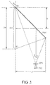
- FIG. 1 The image from the image generator (GI) via a projection optic (OP) is returned using a main mirror M p towards the screen, the mirror M p being typically oriented by an angle ⁇ of 45 ° relative to the screen and making it possible to reduce by half the size between image generator and screen compared to a frontal projection of the image on the screen.
- GI image generator
- OP projection optic
- the invention provides a rear projection device in which the angle between the screen (E) and the deflecting mirror M p can be reduced thanks to the presence of an optical component of the type "mixer" located near the plane on which the final image is formed.
- the subject of the invention is a rear projection device comprising a system (GI) for generating a small image, a projection optic transforming the small image into a large image (I 1 ) and a screen (E) on which the final image (I f ) is formed, characterized in that it comprises at least one deflection component (MR) and an optical mixing component (OM) near the screen (E ), capable of reflecting in the vicinity of an average incidence ⁇ 1 almost all of the image (I 1 ) in an image (I 2 ) and capable of transmitting in the vicinity of an average incidence ⁇ o almost all of the image (I f ) created by reflection of the image (I 2 ) on the component (MR).
- GI system
- GI system
- GI for generating a small image
- a projection optic transforming the small image into a large image (I 1 ) and a screen (E) on which the final image (I f ) is formed
- MR deflection component
- OM optical mixing component
- optical mixing component is characterized by the fact that it is used locally both in transmission and in reflection.
- the two optical components (OM) and (MR) respectively of mixing and return are thus associated to reduce the size of the rear projection device.
- the image generator (GI) is an assembly associating a liquid crystal modulator and a lighting source, having a smaller geometric extent than that coming from cathode ray tubes.
- the overhead projector according to the invention can advantageously comprise two optical return components (OM) 1 and (OM) r so as to further reduce the size of the device by confining the optical path of the light flux, that is to say by making him do several "back and forth". More specifically, this device comprises a component (OM) 1 located near the screen (E), a component (OM) r located between the component (OM) 1 and a conventional optical reference component (MR), the component (OM) r being capable of transmitting almost all of the image (I 1 ) and almost all of the image (I 2 ) created by reflection of the image (I 1 ) on the component (MR) and the component (OM) r being capable of reflecting almost all of the image (I ′ 2 ) created by reflection of almost all of the image (I 2 ) on the optical mixing component (OM) 1 , the image (I ′ 2 ) being reflected in the image (I f ) transmitted by the component (OM) 1 .
- a component (OM) 1 located near the screen (E)
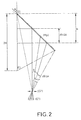
- the projection optics has a focal length of 50 mm (i.e. a projection at approximately 13.5 magnification)
- the image generator has a diagonal of 7.6 cm (3 ")
- the screen has a diagonal of 101 cm (500 x 900 mm 2 )
- the image generator has a diagonal of 7.6 cm (3 ")
- the screen has a diagonal of 101 cm (500 x 900 mm 2 )
- a footprint e 367 mm .
- GI image generator
- OP projection optics
- FIG. 3 illustrates a rear projection device according to the invention made more compact than the rear projection devices according to the prior art, thanks to the association of at least one conventional deflection mirror (MR) and an optical component allowing both the "fallback" of the light beam created by the image generator (GI) and the transmission of said beam at the level of the display screen (E).
- MR deflection mirror
- GI image generator
- E transmission of said beam at the level of the display screen
- FIG. 3 illustrates the general principle of the rear projection device according to the invention.
- an image generator preferably of the liquid crystal modulator (LCD) type associated with a lighting source, having a low incident divergence and a small size
- GI image generator
- LCD liquid crystal modulator
- OP projection optics
- I 1 virtual image
- OM optical mixing component
- I 2 second virtual image
- MR return component
- I f final image
- E transmitted by the component (OM) in the vicinity of the normal incidence ⁇ o .
- optics (OP) and the image generator (GI) are preferably reported in the dimensions e thanks to the presence of a conventional auxiliary return mirror (not shown in FIG. 3).
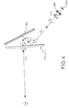
- the optical mixing component (OM) is a polarizing selective cholesteric mirror. It can for example reflect a light which has a polarization of the "left circular” type and transmit without loss a polarization of the "right circular” type.
- the device illustrated in FIG. 4 highlights the different changes in light polarization:
- a linearly polarized light is created, this polarization is transformed with a quarter wave plate ( ⁇ / 4) into a left circular.
- the cholesteric component (OM) reflects this light without changing the polarization unlike a conventional reflector.
- the polarized reflected light "circular left” is then reflected by the reflector (MR) type metal mirror, thereby creating polarized light of the type "circular right” (the arrows indicated on the diagram relate to the direction in which the polarization rotates of light during its optical path).
- Polarized "right circular” light is transmitted by the component (OM) and thus reaches the screen from which the images are perceived by an observer located on the side opposite the image generator (GI) relative to the screen.
- the component (OM) can comprise polymer films containing cholesteric liquid crystal, the high birefringence of this type of material makes it possible to reach significant spectral bands (in which the required conditions of reflection and transmission are satisfied) , greater than 80 nm.
- cholesteric liquid crystals are organized in a helix, the pitch of the helix can vary with temperature conditions the reflected wavelength. You just have to set the temperature to set this no helix, then polymerize the film to freeze the orientation of the liquid crystal dispersed in the polymer.
- the compound mixing function (OM) can be achieved thanks to the presence of a diffraction grating.
- the diffractive grating is designed to be operational according to the angle ⁇ 1 defined in FIG. 3 while the polarization of the light can be arbitrary.
- ⁇ 1 defined in FIG. 3
- the polarization of the light can be arbitrary.
- an image generator we are in the presence of a small extent of the projection source, which makes it possible to reflect almost all of the light emitted even if the network structure has a low angular acceptance. .
- materials such as dichromated gelatin or photopolymer can be used in which it is possible to create index variations which may be between 0.05 and 0.1.
- the strata thus created are parallel to the plane of the component and a non-dispersive wavelength mirror function is obtained: it operates in the vicinity of a given incidence and for a spectral width which mainly depends on the variation of photoinduced index in the material.
- an additional optical mixing component (OM r ) is used located between the component (OM) 1 and the mirror (MR).
- FIG. 6 illustrates the formation of the final image (I f ) on the screen from the image (I 1 ) created by the image generator (GI).
- the image (I 1 ) is transmitted by the component (OM) r , then reflected in the image (I 2 ) by the reflecting mirror (MR).
- the image (I 2 ) is also transmitted by the component (OM) r , and reflected in the image (I ' 2 ) by the component (OM) 1 , to be reflected by the component (OM) r in the image ( I f ) transmitted by the component (OM) 1 .
- optical architectures proposed preferentially use projection objectives (OP) operating on the axis, which has the advantage of simplifying their optical combination.
- OP projection objectives
- the optical architectures proposeentially use projection objectives (OP) operating on the axis, which has the advantage of simplifying their optical combination.
- LCD image generators of the type
Landscapes
- Engineering & Computer Science (AREA)
- Multimedia (AREA)
- Signal Processing (AREA)
- Physics & Mathematics (AREA)
- General Physics & Mathematics (AREA)
- Liquid Crystal (AREA)
- Transforming Electric Information Into Light Information (AREA)
- Projection Apparatus (AREA)
Applications Claiming Priority (2)
| Application Number | Priority Date | Filing Date | Title |
|---|---|---|---|
| FR9504177 | 1995-04-07 | ||
| FR9504177A FR2732783B1 (fr) | 1995-04-07 | 1995-04-07 | Dispositif compact de retroprojection |
Publications (2)
| Publication Number | Publication Date |
|---|---|
| EP0736795A1 true EP0736795A1 (de) | 1996-10-09 |
| EP0736795B1 EP0736795B1 (de) | 2003-08-13 |
Family
ID=9477883
Family Applications (1)
| Application Number | Title | Priority Date | Filing Date |
|---|---|---|---|
| EP96400712A Expired - Lifetime EP0736795B1 (de) | 1995-04-07 | 1996-04-02 | Kompakte Vorrichtung für Retroprojektion |
Country Status (5)
| Country | Link |
|---|---|
| US (1) | US5734447A (de) |
| EP (1) | EP0736795B1 (de) |
| JP (1) | JP3877236B2 (de) |
| DE (1) | DE69629411T2 (de) |
| FR (1) | FR2732783B1 (de) |
Cited By (4)
| Publication number | Priority date | Publication date | Assignee | Title |
|---|---|---|---|---|
| WO1998019213A1 (en) * | 1996-10-31 | 1998-05-07 | Sanyo Electric Co., Ltd. | Back projection display |
| FR2764462A1 (fr) * | 1997-06-10 | 1998-12-11 | Thomson Multimedia Sa | Perfectionnement aux systemes de projection |
| GB2402497A (en) * | 2000-08-16 | 2004-12-08 | Sony Electronics Inc | Optical arrangement for a rear projection television receiver having reduced depth |
| CN110462489A (zh) * | 2017-03-27 | 2019-11-15 | 索尼公司 | 图像显示装置和图像显示元件 |
Families Citing this family (13)
| Publication number | Priority date | Publication date | Assignee | Title |
|---|---|---|---|---|
| CA2193790C (en) | 1995-12-29 | 2001-03-13 | Duke University | Projecting images |
| FR2755530B1 (fr) * | 1996-11-05 | 1999-01-22 | Thomson Csf | Dispositif de visualisation et ecran plat de television utilisant ce dispositif |
| FR2755516B1 (fr) | 1996-11-05 | 1999-01-22 | Thomson Csf | Dispositif compact d'illumination |
| US6227669B1 (en) * | 1998-05-26 | 2001-05-08 | Industrial Technology Research Institute | Illumination device and image projection apparatus comprising the device |
| JP2004535542A (ja) * | 2000-08-18 | 2004-11-25 | リンデ アクチエンゲゼルシヤフト | 空気分離設備の製造法 |
| FR2813128B1 (fr) | 2000-08-18 | 2003-01-17 | Thomson Csf | Dispositif de visualisation a cristal liquide a compensateur de birefringence |
| GB0029340D0 (en) * | 2000-11-30 | 2001-01-17 | Cambridge 3D Display Ltd | Flat panel camera |
| FR2819061B1 (fr) * | 2000-12-28 | 2003-04-11 | Thomson Csf | Dispositif de controle de polarisation dans une liaison optique |
| US6857750B2 (en) * | 2002-06-27 | 2005-02-22 | Koninklijke Philips Electronics N.V. | Offset projection for slim rear projection displays |
| JP2006208786A (ja) * | 2005-01-28 | 2006-08-10 | Dainippon Printing Co Ltd | 反射素子及びそれを備えた投影システム |
| TWI303347B (en) * | 2006-02-07 | 2008-11-21 | Young Optics Inc | Rear projection display apparatus and images adjusting method thereof |
| CN102984489B (zh) * | 2012-12-07 | 2015-09-09 | 广东威创视讯科技股份有限公司 | 一种背投影电视光路设计方法 |
| US9778475B2 (en) * | 2014-11-06 | 2017-10-03 | The United States of America as represesnted by the Secretary of the Air Forice | Universal polarization converter |
Citations (3)
| Publication number | Priority date | Publication date | Assignee | Title |
|---|---|---|---|---|
| US3711188A (en) * | 1970-06-10 | 1973-01-16 | Visidyne Inc | Compact optical display system |
| EP0488590A1 (de) * | 1990-11-30 | 1992-06-03 | THORN EMI plc | Anzeigevorrichtung |
| EP0657769A1 (de) * | 1993-12-10 | 1995-06-14 | Koninklijke Philips Electronics N.V. | Bildprojektionssystem |
Family Cites Families (17)
| Publication number | Priority date | Publication date | Assignee | Title |
|---|---|---|---|---|
| US3941467A (en) * | 1974-10-29 | 1976-03-02 | Kaptron, Inc. | Optical projector/reader |
| JP2569632B2 (ja) * | 1987-11-26 | 1997-01-08 | カシオ計算機株式会社 | 背面投影型ディスプレイ |
| FR2665773B1 (fr) * | 1990-08-10 | 1993-08-20 | Thomson Csf | Dispositif de projection d'images utilisant deux composantes orthogonales de polarisation de la lumiere. |
| FR2669126B1 (fr) * | 1990-11-09 | 1993-01-22 | Thomson Csf | Systeme de visualisation d'images fournies par un modulateur spatial avec transfert d'energie. |
| FR2669127B1 (fr) * | 1990-11-09 | 1993-01-22 | Thomson Csf | Projecteur d'images a deux faisceaux polarises par ecran matriciel. |
| FR2674391B1 (fr) * | 1991-03-19 | 1993-06-04 | Thomson Csf | Dispositif d'intercorrelation large bande et dispositif mettant en óoeuvre ce procede. |
| FR2674708B1 (fr) * | 1991-03-29 | 1997-01-24 | Thomson Csf | Filtre transverse electrique a fonctionnement optique. |
| FR2676302B1 (fr) * | 1991-05-07 | 1993-07-16 | Thomson Csf | Procede de lecture des informations contenues dans un disque optique. |
| FR2676853B1 (fr) * | 1991-05-21 | 1993-12-03 | Thomson Csf | Procede d'ecriture et de lecture optique sur support d'informations a stockage haute densite. |
| FR2680882B1 (fr) * | 1991-08-06 | 1993-10-29 | Thomson Csf | Projecteur d'images a efficacite lumineuse orptimisee. |
| FR2681988A1 (fr) * | 1991-09-27 | 1993-04-02 | Thomson Csf | Laser de puissance a deflexion. |
| FR2681953B1 (fr) * | 1991-10-01 | 1993-11-05 | Thomson Csf | Correlateur de frequences. |
| FR2684198B1 (fr) * | 1991-11-22 | 1994-09-23 | Thomson Csf | Ecran pour projection d'image. |
| FR2685100A1 (fr) * | 1991-12-17 | 1993-06-18 | Thomson Csf | Separateur de polarisations optique et application a un systeme de visualisation. |
| FR2696014B1 (fr) * | 1992-09-18 | 1994-11-04 | Thomson Csf | Miroir à conjugaison de phase. |
| FR2699295B1 (fr) * | 1992-12-15 | 1995-01-06 | Thomson Csf | Dispositif de traitement optique de signaux électriques. |
| FR2707447B1 (fr) * | 1993-07-09 | 1995-09-01 | Thomson Csf | Dispositif de visualisation couleurs. |
-
1995
- 1995-04-07 FR FR9504177A patent/FR2732783B1/fr not_active Expired - Fee Related
-
1996
- 1996-04-02 EP EP96400712A patent/EP0736795B1/de not_active Expired - Lifetime
- 1996-04-02 DE DE69629411T patent/DE69629411T2/de not_active Expired - Fee Related
- 1996-04-03 US US08/626,961 patent/US5734447A/en not_active Expired - Fee Related
- 1996-04-05 JP JP08426396A patent/JP3877236B2/ja not_active Expired - Fee Related
Patent Citations (3)
| Publication number | Priority date | Publication date | Assignee | Title |
|---|---|---|---|---|
| US3711188A (en) * | 1970-06-10 | 1973-01-16 | Visidyne Inc | Compact optical display system |
| EP0488590A1 (de) * | 1990-11-30 | 1992-06-03 | THORN EMI plc | Anzeigevorrichtung |
| EP0657769A1 (de) * | 1993-12-10 | 1995-06-14 | Koninklijke Philips Electronics N.V. | Bildprojektionssystem |
Cited By (6)
| Publication number | Priority date | Publication date | Assignee | Title |
|---|---|---|---|---|
| WO1998019213A1 (en) * | 1996-10-31 | 1998-05-07 | Sanyo Electric Co., Ltd. | Back projection display |
| FR2764462A1 (fr) * | 1997-06-10 | 1998-12-11 | Thomson Multimedia Sa | Perfectionnement aux systemes de projection |
| EP0884898A1 (de) * | 1997-06-10 | 1998-12-16 | THOMSON multimedia | Verbesserungen an Projectionssystemen |
| US6318862B1 (en) | 1997-06-10 | 2001-11-20 | Thomson Multimedia | Projection system employing multiple beam reflections |
| GB2402497A (en) * | 2000-08-16 | 2004-12-08 | Sony Electronics Inc | Optical arrangement for a rear projection television receiver having reduced depth |
| CN110462489A (zh) * | 2017-03-27 | 2019-11-15 | 索尼公司 | 图像显示装置和图像显示元件 |
Also Published As
| Publication number | Publication date |
|---|---|
| FR2732783B1 (fr) | 1997-05-16 |
| US5734447A (en) | 1998-03-31 |
| DE69629411T2 (de) | 2004-07-08 |
| EP0736795B1 (de) | 2003-08-13 |
| DE69629411D1 (de) | 2003-09-18 |
| JPH08339033A (ja) | 1996-12-24 |
| FR2732783A1 (fr) | 1996-10-11 |
| JP3877236B2 (ja) | 2007-02-07 |
Similar Documents
| Publication | Publication Date | Title |
|---|---|---|
| EP0736795B1 (de) | Kompakte Vorrichtung für Retroprojektion | |
| EP0714504B1 (de) | Flüssigkristallprojektor mit holographischer filtervorrichtung | |
| JP3130315B2 (ja) | 照明装置 | |
| EP0633702B1 (de) | Farbanzeigegerät | |
| US7286272B2 (en) | Image display unit | |
| US6595648B1 (en) | Projection display | |
| EP0714522B1 (de) | Holographisches projektionsschirm und herstellungs verfahren | |
| FR2755530A1 (fr) | Dispositif de visualisation et ecran plat de television utilisant ce dispositif | |
| EP0572292B1 (de) | Farbstrahlteiler und Abbildungsprojektor der diesen benutzt | |
| EP0485268A1 (de) | Matrix-Bildprojektor mit zwei polarisierten Strahlen | |
| EP0492640B1 (de) | Projektor mit Hologramm | |
| WO1995034832A1 (fr) | Ecran de projection holographique et procede de realisation | |
| EP0677230B1 (de) | Farbanzeigegerät und herstellungsverfahren | |
| US5877824A (en) | System for illuminating a liquid-crystal screen | |
| EP0937273B1 (de) | Kompakte vorrichtung für beleuchtung | |
| JPH11295816A (ja) | 投射スクリーン及び投射表示装置 | |
| EP0740169B1 (de) | Beleuchtungsvorrichtung | |
| FR2693004A1 (fr) | Dispositif de collimation de faible encombrement, en particulier pour visuel de casque. | |
| EP0478425B1 (de) | Vorrichtung zur Erzeugung von mehreren Lichtstrahlen | |
| CN215897911U (zh) | 一种投影机光学装置和投影机 | |
| JPH11308640A (ja) | 虚像結像方法及び虚像結像装置 | |
| FR2858068A1 (fr) | Systeme de projection d'images pour viseur tete haute | |
| FR2699688A1 (fr) | Dispositif de filtrage optique et application à un projecteur à cristal liquide. | |
| FR2745917A1 (fr) | Dispositif de visualisation pour viseur de casque | |
| FR2685101A1 (fr) | Dispositif de collimation de faible encombrement a grand champ et luminosite elevee. |
Legal Events
| Date | Code | Title | Description |
|---|---|---|---|
| PUAI | Public reference made under article 153(3) epc to a published international application that has entered the european phase |
Free format text: ORIGINAL CODE: 0009012 |
|
| AK | Designated contracting states |
Kind code of ref document: A1 Designated state(s): DE GB IT NL |
|
| 17P | Request for examination filed |
Effective date: 19970210 |
|
| RAP1 | Party data changed (applicant data changed or rights of an application transferred) |
Owner name: THALES |
|
| 17Q | First examination report despatched |
Effective date: 20011029 |
|
| GRAH | Despatch of communication of intention to grant a patent |
Free format text: ORIGINAL CODE: EPIDOS IGRA |
|
| RIN1 | Information on inventor provided before grant (corrected) |
Inventor name: JOUBERT, CECILE Inventor name: SPITZ, ERICH Inventor name: HUIGNARD, JEAN-PIERRE Inventor name: LOISEAUX, BRIGITTE |
|
| GRAH | Despatch of communication of intention to grant a patent |
Free format text: ORIGINAL CODE: EPIDOS IGRA |
|
| GRAA | (expected) grant |
Free format text: ORIGINAL CODE: 0009210 |
|
| AK | Designated contracting states |
Designated state(s): DE GB IT NL |
|
| REG | Reference to a national code |
Ref country code: GB Ref legal event code: FG4D Free format text: NOT ENGLISH |
|
| REF | Corresponds to: |
Ref document number: 69629411 Country of ref document: DE Date of ref document: 20030918 Kind code of ref document: P |
|
| GBT | Gb: translation of ep patent filed (gb section 77(6)(a)/1977) |
Effective date: 20031113 |
|
| PLBE | No opposition filed within time limit |
Free format text: ORIGINAL CODE: 0009261 |
|
| STAA | Information on the status of an ep patent application or granted ep patent |
Free format text: STATUS: NO OPPOSITION FILED WITHIN TIME LIMIT |
|
| 26N | No opposition filed |
Effective date: 20040514 |
|
| PGFP | Annual fee paid to national office [announced via postgrant information from national office to epo] |
Ref country code: NL Payment date: 20090405 Year of fee payment: 14 Ref country code: IT Payment date: 20090421 Year of fee payment: 14 Ref country code: DE Payment date: 20090327 Year of fee payment: 14 |
|
| PGFP | Annual fee paid to national office [announced via postgrant information from national office to epo] |
Ref country code: GB Payment date: 20090401 Year of fee payment: 14 |
|
| REG | Reference to a national code |
Ref country code: NL Ref legal event code: V1 Effective date: 20101101 |
|
| GBPC | Gb: european patent ceased through non-payment of renewal fee |
Effective date: 20100402 |
|
| PG25 | Lapsed in a contracting state [announced via postgrant information from national office to epo] |
Ref country code: NL Free format text: LAPSE BECAUSE OF NON-PAYMENT OF DUE FEES Effective date: 20101101 |
|
| PG25 | Lapsed in a contracting state [announced via postgrant information from national office to epo] |
Ref country code: DE Free format text: LAPSE BECAUSE OF NON-PAYMENT OF DUE FEES Effective date: 20101103 |
|
| PG25 | Lapsed in a contracting state [announced via postgrant information from national office to epo] |
Ref country code: GB Free format text: LAPSE BECAUSE OF NON-PAYMENT OF DUE FEES Effective date: 20100402 Ref country code: IT Free format text: LAPSE BECAUSE OF NON-PAYMENT OF DUE FEES Effective date: 20100402 |