EP0736868A1 - Verfahren zur Feststellung einer Kassette - Google Patents
Verfahren zur Feststellung einer Kassette Download PDFInfo
- Publication number
- EP0736868A1 EP0736868A1 EP96870031A EP96870031A EP0736868A1 EP 0736868 A1 EP0736868 A1 EP 0736868A1 EP 96870031 A EP96870031 A EP 96870031A EP 96870031 A EP96870031 A EP 96870031A EP 0736868 A1 EP0736868 A1 EP 0736868A1
- Authority
- EP
- European Patent Office
- Prior art keywords
- cassette
- slide
- type
- stop
- shoe
- Prior art date
- Legal status (The legal status is an assumption and is not a legal conclusion. Google has not performed a legal analysis and makes no representation as to the accuracy of the status listed.)
- Withdrawn
Links
- 238000001514 detection method Methods 0.000 title claims description 4
- 238000003780 insertion Methods 0.000 claims abstract description 14
- 230000037431 insertion Effects 0.000 claims abstract description 14
- 238000006073 displacement reaction Methods 0.000 claims abstract description 4
- 230000007246 mechanism Effects 0.000 claims description 6
- 230000000903 blocking effect Effects 0.000 claims description 4
- 230000000670 limiting effect Effects 0.000 claims description 2
- 238000013519 translation Methods 0.000 description 5
- 238000005452 bending Methods 0.000 description 2
- 238000004519 manufacturing process Methods 0.000 description 2
- 230000001681 protective effect Effects 0.000 description 2
- 230000002829 reductive effect Effects 0.000 description 2
- 238000013459 approach Methods 0.000 description 1
- 238000006243 chemical reaction Methods 0.000 description 1
- 230000002349 favourable effect Effects 0.000 description 1
- 230000007257 malfunction Effects 0.000 description 1
- 239000000463 material Substances 0.000 description 1
- 238000012986 modification Methods 0.000 description 1
- 230000004048 modification Effects 0.000 description 1
- 210000000056 organ Anatomy 0.000 description 1
- 230000036961 partial effect Effects 0.000 description 1
- 230000000284 resting effect Effects 0.000 description 1
- 239000011435 rock Substances 0.000 description 1
- 238000012549 training Methods 0.000 description 1
- 238000012546 transfer Methods 0.000 description 1
- 230000007704 transition Effects 0.000 description 1
- 238000012795 verification Methods 0.000 description 1
Images
Classifications
-
- G—PHYSICS
- G11—INFORMATION STORAGE
- G11B—INFORMATION STORAGE BASED ON RELATIVE MOVEMENT BETWEEN RECORD CARRIER AND TRANSDUCER
- G11B15/00—Driving, starting or stopping record carriers of filamentary or web form; Driving both such record carriers and heads; Guiding such record carriers or containers therefor; Control thereof; Control of operating function
- G11B15/675—Guiding containers, e.g. loading, ejecting cassettes
- G11B15/67544—Guiding containers, e.g. loading, ejecting cassettes with movement of the cassette parallel to its main side and subsequent movement perpendicular thereto, i.e. front loading
- G11B15/67547—Guiding containers, e.g. loading, ejecting cassettes with movement of the cassette parallel to its main side and subsequent movement perpendicular thereto, i.e. front loading the two movements being made by the cassette holder
-
- G—PHYSICS
- G11—INFORMATION STORAGE
- G11B—INFORMATION STORAGE BASED ON RELATIVE MOVEMENT BETWEEN RECORD CARRIER AND TRANSDUCER
- G11B15/00—Driving, starting or stopping record carriers of filamentary or web form; Driving both such record carriers and heads; Guiding such record carriers or containers therefor; Control thereof; Control of operating function
- G11B15/18—Driving; Starting; Stopping; Arrangements for control or regulation thereof
- G11B15/44—Speed-changing arrangements; Reversing arrangements; Drive transfer means therefor
- G11B15/442—Control thereof
-
- G—PHYSICS
- G11—INFORMATION STORAGE
- G11B—INFORMATION STORAGE BASED ON RELATIVE MOVEMENT BETWEEN RECORD CARRIER AND TRANSDUCER
- G11B15/00—Driving, starting or stopping record carriers of filamentary or web form; Driving both such record carriers and heads; Guiding such record carriers or containers therefor; Control thereof; Control of operating function
- G11B15/675—Guiding containers, e.g. loading, ejecting cassettes
Definitions
- the present invention relates to apparatus for recording and / or reading information carried by a medium contained in a cassette, cartridge or case. It relates in particular to the mechanisms ensuring the transfer of said supports between their operative and inoperative positions.
- a cassette of a first type called digital compact cassette or DCC has recently been introduced on the market and ensures the storage of information in digital form. Intended to succeed the cassette of the second type called compact analog or CC available for many years, the DCC cassette has a case similar to that of the CC cassette so that the new tape recorders put on sale accept these two types of cassette for the recording and / or reproduction of information and allow an easy and inexpensive transition from the CC cassette to the DCC cassette.
- the DCC digital cassette has only one side and only one operating direction, and as it is perfectly parallelepipedic in shape, the user, especially in the case of devices for cars, is very likely to present it. inappropriately, for example upside down or inverted front / rear faces with the risk of damaging reading and / or recording elements and / or blocking the loading device and therefore the device concerned.
- European patent application EP 0 444 623 proposes a device which discerns the type of cassette inserted, but on the one hand it blocks the insertion movement only at the end of the travel and very often the user then tends to force the mechanism because it does not realize that the cassette has been inserted incorrectly and on the other hand, it is only applicable to a loading of the cassettes by their long side which is valid for home appliances but not applicable to devices for cars because the cassette is always loaded by their short side for imperative reasons of space.
- European application N ° 0 514 983 relates to a loading of the cassettes by their short side but if the device which it describes distinguishes a digital cassette from an analog cassette, this only occurs when the cassettes are correctly presented by the user.
- the digital cassettes being perfectly parallelepipedic, the risk of an incorrect insertion is great and in this case this device considers any digital cassette badly presented as an analog cassette which is not only an error but also a potential source of major malfunction and so of damage or device failure.
- the device uses numerous levers and springs, which requires fairly precise manufacture and assembly and is hardly favorable to reliability, especially for devices placed in vehicles.
- European application 0 549 376 describes a device simply ensuring the opening of the protective flap of a digital cassette when it is correctly presented. There is therefore neither detection of the type of cassette, nor verification of its correct insertion.
- the object of the present invention is therefore to remedy these drawbacks by proposing simple, reliable and easy-to-use means which verify the correct presentation of the cassette and / or ensure the detection of the type thereof without risk of error, on the one hand, only allow the loading of correctly presented cassettes and / or on the other hand, ensuring that both mechanical and electronic means of reading, recording and driving correspond to the type of cassette inserted.
- a second object of the invention is to propose means using only a very limited number of parts so as to obtain high reliability and a reduced manufacturing cost.
- a third object of the invention is to provide means requiring only a small footprint so that they can be easily incorporated into devices intended for automotive applications where the available space is excessively limited.
- Another object of the invention is to propose means blocking the insertion of a poorly presented cassette as soon as possible and preferably before any displacement of the housing receiving the cassette so that the user is never tempted to force the mechanism.
- the device which is the subject of the invention is essentially characterized by the content of the main claim.
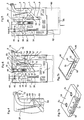
- the analog cassette 50 and the digital cassette 60 have substantially the same parallelepiped shape, the same size; however, the cassette 60 of the first type has its own discontinuity 62: a depression associated with a flap 68 protecting access to the magnetic support, while the cassette 50 of the second type is distinguished by a particular discontinuity 52: a protuberance on both sides of the same side.
- the loading device mainly comprises a housing 1 intended to receive a cassette 50, 60 and then effecting, under the control of an electric motor, a horizontal and then vertical displacement to bring the cassette into the operative position.
- a housing 1 intended to receive a cassette 50, 60 and then effecting, under the control of an electric motor, a horizontal and then vertical displacement to bring the cassette into the operative position.
- the loading mechanism advantageously refer to Belgian patent N ° 891,045 of the applicant.
- European patent application No. 0 667 613 for a complete description of the operation of the reading and / or recording device.
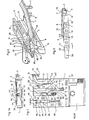
- the housing 1 comprises in particular (see Figures 1, 2 and 3) a lever 3 which can tilt and pivot around an axis 5 fixed on this housing.
- Elastic means 6 anchored on the one hand to the axis 5 and on the other hand to a tab 72 of the lever 3 hold it against the upper surface of the housing 1; the tab 72 being able to actuate a switch 70 arranged on the frame of the apparatus and indicating the type of cassette inserted.
- the lever 3 also carries a finger 7 which extends downwards along a side wall of the housing 1 and a shoe 8 intended to cooperate with a cassette 60, respectively 50 introduced into the housing 1.
- the lever 3 has at its free end 4 a fold forming a stop 9 and cooperates with two stops 15 and 16 of a slide 18, the stop 16 limiting at any time the pivoting of the lever 3 in the clockwise direction ( Figures 1, 2) imparted by a spring 21 fixed to the housing 1 and to the lever 3.
- This slide 18 is mounted through a slot 17 made in the upper part of the housing 1 so that it can be translated there (FIG. 1) and has at its rear end a tab 19 s' extending downward to cooperate with the front face of a cassette 50, 60.
- the slide 18 carries a flexible tongue 20, having at its ends a tab 24 and a shoe 86 intended to cooperate with an orifice specially provided in the cassettes both digital ues 60 than analog 50.
- the slide 18 has an inverted L shape and on its short side is fixed one end of a pin spring 30 the other end of which is fixed on a movable plate 38 also mounted in translation on the housing 1 through a slot 37.
- This movable plate 38 is subjected to the action of a spring 39 attached to the housing 1 and has at its opposite end a thickness 44 intended to cooperate with a hook 46 mounted on a blade spring 48 fixed to the frame of the device.
- a shoe 86 is pivotally mounted around an axis 88 carried by the front lateral ends 80 acting as fixed shoes of the tongue 20 (the one on the right is omitted in the drawing for a better understanding of this assembly).
- This movable shoe 86 has a profile 90 comprising a front part 92 slightly inclined to cooperate with the upper surface of a cassette of the first type (digital) 60 and a rear part 94 strongly inclined in order to engage the periphery of an opening 54 made in the casing of a cassette of the second type (analog) 50 to access the reels of magnetic tape.
- a tongue 81 also made of flexible material, preferably molded with tongue 20, makes this shoe 86 pivot downwards. Two lateral lugs 96 limit this pivoting by resting on the rear of the fixed shoes 80.
- the shoe 86 is slightly raised against the tongue 81 during their introduction and the part 92 of the profile 90 allows easy sliding of the cassette.
- the shoe 86 is pivoted downwards, the said profile 94 engaging in the opening 54 to link the cassette 50 to the slide 18.
- the anchor point of the spring 30 on the slide 18 catches up then exceeds its anchor point on the movable plate 38. From this moment, the slide 18 and therefore the cassette 50 undergo the influence of the spring 30 which pushes them both to the bottom of the housing 1 while by reaction, the other end of the spring 30 pushes the movable plate 38 forward. All of these elements are then in the position shown in FIG. 6 and a boss 67 of the slide 18 actuates the switch 65 controlling means, such as an electric motor, effecting the continuation of the loading movement; the switch 70 indicating the presence of an analog type cassette.
- the switch 65 controlling means such as an electric motor
- the profile 90 of the shoe 86 meets the front edge of the cassette 60 and then its upper face.
- the front part 92 of the profile pivots the movable shoe 86 upwards, it remains parallel to the profile 82 of the fixed shoes 80 which allow the cassette 60 to slide freely.
- the stop 16 recedes slightly allowing the pivoting of the lever 3 around the axis 5 in clockwise direction (FIG. 4) because the finger 7 enters the discontinuity or depression 62 provided only on one side of the upper face of any cassette 60 of the first type for retaining the flap 68.
- the stop 9 of the lever 3 then escapes the stop 15 and the slide 18 can be freely translated.
- the continued translation of the cassette 60 ensures that the finger 7 remains substantially at the same level to limit the movement of the flap 68 and therefore give access to the magnetic support.
- the lever 3 continues to pivot clockwise until the finger 7, following the profile 63 of the depression 62, ends in the notch 64 ( Figures 4 and 6) to lock the flap 68 in its position d maximum opening.
- the pivoting of the tab 72 of the lever 3 actuates the switch 70 (FIG. 6) indicating that the inserted cassette is of the first type (digital).
- the tab 24 carried by the tongue 20 enters the depression 66 provided only on the upper face of the casing of this type of cassette 60 (FIG. 7b) and links the cassette 60 to the slide 18.
- the anchor point of the spring 30 on the slide 18 catches up then exceeds its anchor point on the movable plate 38 and therefore the slide 18 and the cassette 60 are both pushed towards the bottom of the housing 1 by the spring 30 and the switch 65 is actuated by the boss 67 while the movable plate 38 is pushed forward.
- the proposed device provides total security since it prevents any poorly presented cassette, whatever its type, from correctly entering the housing 1 and it clearly distinguishes an analog cassette from a digital cassette.
- the proposed device provides very high reliability of use.
- the profile 94 ensures a slight pivoting upwards of the fixed shoes 80 by bending of the tongue 20 and it then escapes the opening 54 thus releasing The tape.
- the tab 24 escapes the opening 66 by bending the support 20 and the profile 90 of the movable shoe 86 having a radius of curvature much greater than that of the opening 66 cannot penetrate opening 66 and therefore hinder the sliding of the digital cassette 60.
Landscapes
- Packaging Of Annular Or Rod-Shaped Articles, Wearing Apparel, Cassettes, Or The Like (AREA)
- Automatic Tape Cassette Changers (AREA)
Applications Claiming Priority (2)
| Application Number | Priority Date | Filing Date | Title |
|---|---|---|---|
| BE9500314A BE1009341A3 (fr) | 1995-04-05 | 1995-04-05 | Dispositif de detection du type de cassettes. |
| BE9500314 | 1995-04-05 |
Publications (1)
| Publication Number | Publication Date |
|---|---|
| EP0736868A1 true EP0736868A1 (de) | 1996-10-09 |
Family
ID=3888910
Family Applications (1)
| Application Number | Title | Priority Date | Filing Date |
|---|---|---|---|
| EP96870031A Withdrawn EP0736868A1 (de) | 1995-04-05 | 1996-03-13 | Verfahren zur Feststellung einer Kassette |
Country Status (4)
| Country | Link |
|---|---|
| US (1) | US5675451A (de) |
| EP (1) | EP0736868A1 (de) |
| JP (1) | JPH08287564A (de) |
| BE (1) | BE1009341A3 (de) |
Families Citing this family (2)
| Publication number | Priority date | Publication date | Assignee | Title |
|---|---|---|---|---|
| US6052253A (en) * | 1997-11-24 | 2000-04-18 | Gateway 2000, Inc. | Dual format tape drive |
| US7006319B2 (en) * | 2003-03-27 | 2006-02-28 | Hewlett-Packard Development Company, L.P. | Media-detection system and method for identifying types of data cartridges |
Citations (6)
| Publication number | Priority date | Publication date | Assignee | Title |
|---|---|---|---|---|
| BE891045A (fr) * | 1981-11-09 | 1982-03-01 | Staar Sa | Dispositif d'insertion et d'ejection de cassettes pour appareil d'enregistrement et de lecture a bande magnetique |
| DE3346893A1 (de) * | 1982-12-23 | 1984-06-28 | Clarion Co., Ltd., Tokio/Tokyo | Magnetbandgeraet |
| US4636890A (en) * | 1983-05-16 | 1987-01-13 | Tandberg Data A/S | Magnetic tape recorder |
| EP0366191A2 (de) * | 1988-10-25 | 1990-05-02 | Philips Patentverwaltung GmbH | Magnetbandkassettengerät mit einer Steuervorrichtung |
| EP0444623A2 (de) * | 1990-02-26 | 1991-09-04 | Matsushita Electric Industrial Co., Ltd. | Bandkassette-Lademechanismus |
| EP0549376A2 (de) * | 1991-12-27 | 1993-06-30 | Matsushita Electric Industrial Co., Ltd. | Bandaufnahmegerät mit einem Kassettenfachöffnungsmechanismus |
Family Cites Families (7)
| Publication number | Priority date | Publication date | Assignee | Title |
|---|---|---|---|---|
| US4546396A (en) * | 1981-11-09 | 1985-10-08 | Staar, S. A. | Loading and unloading system for recording and/or playback apparatus |
| JPH0322249A (ja) * | 1989-01-18 | 1991-01-30 | Nakamichi Corp | ディスクカートリッジのシャッター開放機構 |
| YU123090A (sh) * | 1989-07-03 | 1994-04-05 | N.V. Philips Gloelampenfabrieken | Sistem za snemanje/reprodukcijo signalov na/s magnetnega traku v kaseti |
| US5231553A (en) * | 1989-12-18 | 1993-07-27 | U.S. Philips Corporation | System comprising magnetic tape cassette apparatus and two different types of magnetic tape cassettes playable in such apparatus |
| DE4116920A1 (de) * | 1991-05-24 | 1992-11-26 | Philips Patentverwaltung | Anordnung, bestehend aus einem magnetbandkassettengeraet mit einem laufwerk und mit lademechanismus fuer magnetbandkassetten und aus einer magnetbandkassette |
| JPH087922B2 (ja) * | 1991-05-27 | 1996-01-29 | 日本マランツ株式会社 | テープレコーダのカセット送り装置 |
| DE4129945A1 (de) * | 1991-09-09 | 1993-03-11 | Philips Patentverwaltung | Schwenkvorrichtung fuer eine abdeckklappe am kassettenschacht eines magnetbandkassettengeraetes |
-
1995
- 1995-04-05 BE BE9500314A patent/BE1009341A3/fr not_active IP Right Cessation
-
1996
- 1996-03-13 EP EP96870031A patent/EP0736868A1/de not_active Withdrawn
- 1996-03-15 US US08/616,292 patent/US5675451A/en not_active Expired - Fee Related
- 1996-04-01 JP JP8106149A patent/JPH08287564A/ja active Pending
Patent Citations (6)
| Publication number | Priority date | Publication date | Assignee | Title |
|---|---|---|---|---|
| BE891045A (fr) * | 1981-11-09 | 1982-03-01 | Staar Sa | Dispositif d'insertion et d'ejection de cassettes pour appareil d'enregistrement et de lecture a bande magnetique |
| DE3346893A1 (de) * | 1982-12-23 | 1984-06-28 | Clarion Co., Ltd., Tokio/Tokyo | Magnetbandgeraet |
| US4636890A (en) * | 1983-05-16 | 1987-01-13 | Tandberg Data A/S | Magnetic tape recorder |
| EP0366191A2 (de) * | 1988-10-25 | 1990-05-02 | Philips Patentverwaltung GmbH | Magnetbandkassettengerät mit einer Steuervorrichtung |
| EP0444623A2 (de) * | 1990-02-26 | 1991-09-04 | Matsushita Electric Industrial Co., Ltd. | Bandkassette-Lademechanismus |
| EP0549376A2 (de) * | 1991-12-27 | 1993-06-30 | Matsushita Electric Industrial Co., Ltd. | Bandaufnahmegerät mit einem Kassettenfachöffnungsmechanismus |
Also Published As
| Publication number | Publication date |
|---|---|
| US5675451A (en) | 1997-10-07 |
| JPH08287564A (ja) | 1996-11-01 |
| BE1009341A3 (fr) | 1997-02-04 |
Similar Documents
| Publication | Publication Date | Title |
|---|---|---|
| US4592039A (en) | Disc player | |
| FR2475268A1 (fr) | Boitier pour support d'enregistrement en forme de disque | |
| FR2475776A1 (fr) | Appareil de lecture de support d'enregistrement en forme de disque | |
| FR2529701A1 (fr) | Cassette pour disque d'enregistrement et de lecture d'informations | |
| FR2535099A1 (fr) | Appareil d'enregistrement et/ou de reproduction magnetiques a disque souple | |
| FR2545253A1 (fr) | Cassette de bande | |
| FR2503914A1 (fr) | Recipient pour cassette a bande magnetique | |
| US6056117A (en) | CD carrying case having a built-in pop cover | |
| US6450332B1 (en) | Case for storing a compact disc | |
| FR2702079A1 (fr) | Assemblage pour électrophone. | |
| EP0183672A2 (de) | Aufnahme- und Wiedergabegerät mit Fronteinschub | |
| EP1003171A1 (de) | Kassette für Datenträger | |
| EP0624873A1 (de) | Verfahren zur Gestattung des fehlerfreien Laden von Kassetten in einen Einführungsraum eines Lese und/oder Schreibgeräts | |
| BE1009341A3 (fr) | Dispositif de detection du type de cassettes. | |
| EP0570342B1 (de) | Plattenkassette | |
| FR2619651A1 (fr) | Dispositif de changement automatique de cassette | |
| FR2767955A1 (fr) | Un mecanisme de maintien de cartouche pour un lecteur a cartouche amovible | |
| EP1559103B1 (de) | Schutzbehälter für einen plattenförmigen träger numerischer daten | |
| EP0415805B1 (de) | Pfandvorrichtung für schiebbare Einkaufwagen und damit versehene Einkaufswagen | |
| CH659337A5 (en) | Cassette with disc | |
| FR2557346A1 (fr) | Dispositif de positionnement et de blocage de disques dans un logement | |
| FR2670941A1 (fr) | Cassette de bande a ressort unique de rappel. | |
| BE894483A (fr) | Casier de rangement de cassettes | |
| FR2471022A1 (fr) | Enveloppe protectrice pour un videodisque | |
| EP0422989B1 (de) | Plattenschutzkassette |
Legal Events
| Date | Code | Title | Description |
|---|---|---|---|
| PUAI | Public reference made under article 153(3) epc to a published international application that has entered the european phase |
Free format text: ORIGINAL CODE: 0009012 |
|
| AK | Designated contracting states |
Kind code of ref document: A1 Designated state(s): CH DE FR GB IT LI NL PT |
|
| STAA | Information on the status of an ep patent application or granted ep patent |
Free format text: STATUS: THE APPLICATION HAS BEEN WITHDRAWN |
|
| 18W | Application withdrawn |
Withdrawal date: 19970324 |