EP0736889A2 - Dispositif de contact électrique à fiche et douille pour un fusible plat - Google Patents
Dispositif de contact électrique à fiche et douille pour un fusible plat Download PDFInfo
- Publication number
- EP0736889A2 EP0736889A2 EP96102059A EP96102059A EP0736889A2 EP 0736889 A2 EP0736889 A2 EP 0736889A2 EP 96102059 A EP96102059 A EP 96102059A EP 96102059 A EP96102059 A EP 96102059A EP 0736889 A2 EP0736889 A2 EP 0736889A2
- Authority
- EP
- European Patent Office
- Prior art keywords
- flat
- contact
- upright
- contacting device
- contact element
- Prior art date
- Legal status (The legal status is an assumption and is not a legal conclusion. Google has not performed a legal analysis and makes no representation as to the accuracy of the status listed.)
- Granted
Links
- 239000011810 insulating material Substances 0.000 claims abstract description 10
- 239000004020 conductor Substances 0.000 claims abstract description 4
- 210000002105 tongue Anatomy 0.000 claims description 17
- 239000002184 metal Substances 0.000 claims description 9
- 238000003780 insertion Methods 0.000 claims description 6
- 230000037431 insertion Effects 0.000 claims description 6
- 238000005192 partition Methods 0.000 description 5
- 210000000078 claw Anatomy 0.000 description 2
- 238000004519 manufacturing process Methods 0.000 description 2
- 238000002788 crimping Methods 0.000 description 1
- 238000011161 development Methods 0.000 description 1
- 230000018109 developmental process Effects 0.000 description 1
- 230000002093 peripheral effect Effects 0.000 description 1
- 239000013589 supplement Substances 0.000 description 1
Images



Classifications
-
- H—ELECTRICITY
- H01—ELECTRIC ELEMENTS
- H01H—ELECTRIC SWITCHES; RELAYS; SELECTORS; EMERGENCY PROTECTIVE DEVICES
- H01H85/00—Protective devices in which the current flows through a part of fusible material and this current is interrupted by displacement of the fusible material when this current becomes excessive
- H01H85/02—Details
- H01H85/20—Bases for supporting the fuse; Separate parts thereof
- H01H85/203—Bases for supporting the fuse; Separate parts thereof for fuses with blade type terminals
- H01H85/2035—Bases for supporting the fuse; Separate parts thereof for fuses with blade type terminals for miniature fuses with parallel side contacts
-
- H—ELECTRICITY
- H01—ELECTRIC ELEMENTS
- H01H—ELECTRIC SWITCHES; RELAYS; SELECTORS; EMERGENCY PROTECTIVE DEVICES
- H01H85/00—Protective devices in which the current flows through a part of fusible material and this current is interrupted by displacement of the fusible material when this current becomes excessive
- H01H85/02—Details
- H01H85/20—Bases for supporting the fuse; Separate parts thereof
- H01H85/205—Electric connections to contacts on the base
- H01H2085/206—Electric connections to contacts on the base being tappable, e.g. terminals on the fuse or base being arranged so as to permit an additional connector to be engaged therewith
-
- H—ELECTRICITY
- H01—ELECTRIC ELEMENTS
- H01H—ELECTRIC SWITCHES; RELAYS; SELECTORS; EMERGENCY PROTECTIVE DEVICES
- H01H85/00—Protective devices in which the current flows through a part of fusible material and this current is interrupted by displacement of the fusible material when this current becomes excessive
- H01H85/02—Details
- H01H85/20—Bases for supporting the fuse; Separate parts thereof
- H01H2085/2075—Junction box, having holders integrated with several other holders in a particular wiring layout
- H01H2085/208—Junction box, having holders integrated with several other holders in a particular wiring layout specially adapted for vehicles
-
- H—ELECTRICITY
- H01—ELECTRIC ELEMENTS
- H01H—ELECTRIC SWITCHES; RELAYS; SELECTORS; EMERGENCY PROTECTIVE DEVICES
- H01H85/00—Protective devices in which the current flows through a part of fusible material and this current is interrupted by displacement of the fusible material when this current becomes excessive
- H01H85/02—Details
- H01H85/20—Bases for supporting the fuse; Separate parts thereof
- H01H85/2045—Mounting means or insulating parts of the base, e.g. covers, casings
Definitions
- the invention relates to an electrical plug-in contact device of an electrical flat fuse with at least two contact elements made from a stamped sheet metal part.
- DE 31 15 435 A1 discloses a miniature electrical flat fuse which can be plugged onto a contact housing.
- the invention described below is concerned with the contacting of such flat fuses, which exist in many different embodiments, in particular with regard to their current-carrying fuse elements.
- These flat fuses consist of two flat tabs arranged in a plane next to one another at a distance, standardized in their dimensions, from a current-conducting metal sheet, which in one piece merge into current-carrying webs, between which a fuse element is arranged, following the front plug-in area.
- the current conducting bars and the fuse element are encased in a narrow, cuboid-shaped insulating material body from which the tabs protrude.
- upright contact elements designed as fork-shaped flat elements, for example in DE 43 06 795 C2 can be described.
- These known upright contact elements essentially consist of a stamped sheet metal part and have a conductor wire connection device, for example in the form of crimp claws or contact tabs for plug contacts, and a contact area for a flat tongue of a flat fuse.
- the contacting area is designed as a fork-shaped flat element which has two upright spring arms which are arranged coplanarly in the sheet metal plane and separated from one another by a slot, and spring fork arms which are resilient transversely to the sheet plane and which act on a plug-in tongue in the area of the mouth of the slot at a contact point on a flat tongue of a flat fuse Generate contact forces, the spring arms being connected via a spring arm base lying in the same sheet metal plane as the fork spring arms.
- the contact area each has an additional spring arm, which is arranged laterally on the outside next to one of the fork spring arms in the same sheet plane and is integrally connected on the one hand to the spring arm base and on the other hand to the fork spring arms in the region of the contact point.
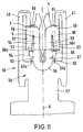
- an over-spring can be provided which biases the fork spring arms upright toward one another.
- the over-spring is designed as a flat, U-shaped spring placed on the flat contacting part of the contact element, the base of which is arranged in the area of the slot base, and the legs of which extend into the area of the contact point of the fork spring arms and are bent from the outside to the outside Apply rag (see Fig. 11).
- each tab of a flat fuse is contacted with an upright contact element, each upright contact element being seated in a contact element chamber of the contact housing and, in a manner known per se, secured with a locking slide device against being pulled out, being placed crosswise on a tab.
- Crosswise means that the plane of the tab is perpendicular to the plane of the upright contact element.
- an upright contact element 1 is used according to FIG. 1, to which, instead of crimping claws, a contact tab 2 in the form of a sheet metal strip is connected for a contact point distribution.
- the metal strip or the contact lug 2 is bent at right angles from the plane of the upright contact element and is therefore in a plane perpendicular to the plane of the upright contact element.
- the contact lug 2 extends in a Z-shape and has the connecting web 3 bent at right angles, the connecting web 4 adjoining it, which extends parallel to the contact area 6 of the upright contact element, and the contact web 5 which extends perpendicularly away from the contact area 6 and is at a height the contact point of the upright contact element is arranged.
- the contact bridge protrudes e.g. in two further contact element chambers of the contact housing by reaching through the contact element chamber walls.
- the contact web 5 is contacted by a further upright contact element 7, 8 in the manner of indirect or branched or second plug contact points with respect to a flat tongue of the flat fuse.
- This known contact point distribution device requires a large number of contact element chambers of the same spatial shape in one Fuse contact housings that consume a lot of insulating material and take up a lot of space, so that the dimensions of the fuse contact housing are correspondingly large.
- a special manufacture of an upright contact element with respect to the contact lug for example according to FIG. 1, is required, which in turn requires special spatial shapes of the contact housing, in particular with regard to the contact chambers.
- the contact point-distributing upright contact element of a special design also requires a complicated locking slide device.
- a major disadvantage of the known contact point distribution is that indirect second plug contact points branched off from a contact lug are created, which are known to be risky with regard to correct contacting.
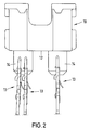
- a flat fuse 10 of a known type has a narrow, flat-body insulating material body 11, with which the current-carrying webs, not shown, and the fuse element, not shown, are encased.
- the uniform flat tabs 14 protrude from the bottom of the insulating material 11 on the underside, arranged in a plane at a lateral distance from one another.
- the insulating material body 11 is provided with a plug-limiting edge 12 which runs in a plane which is perpendicular to the plane of the flat tabs.
- two upright contact elements 13 are placed on at least one tab 14, preferably the same type (Fig. 2, Fig.
- the contact housing 20 made of an insulating material has essentially a cuboid spatial shape with a bottom wall 21, two narrow side walls 22, 23 and two broad side walls 24, 25.
- Two or three blind hole-shaped contact element chambers 26, 27 which are essentially rectangular in cross section are introduced into the contact housing 20, that begin on the side opposite the bottom wall 21 with free plug openings 28, 29 and end on the bottom wall 21.
- In the bottom wall 21 are two identical, parallel to the walls 24, 25, at a lateral distance from each other, located approximately in the center of the slot 30, 31, each opening into a contact element chamber 26, 27, and the dimensions of each Cross-sectional dimension of a flat tongue 14 of a flat fuse 10 is adapted, and the distance from each other corresponds to the distance between the flat tongues 14. If three contact element chambers are provided according to the invention, a plug-in slot opens into two adjacent contact element chambers.
- a bearing block 32 protruding perpendicularly from the bottom wall 21 On the side next to the slot 30 in the direction of the narrow side wall 22, a bearing block 32 protruding perpendicularly from the bottom wall 21 is formed, which has a guide channel 34 which is essentially U-shaped in cross section and runs parallel to its longitudinal extension and is open towards the slot 30.
- a bearing block 33 protruding perpendicularly from the bottom wall 21 is formed, which has a guide groove 35 which is essentially U-shaped in cross section and runs parallel to its longitudinal extension and is open towards the slot 31.
- a flat fuse 10 can be approximately fitted, the flat tabs 14 of which extend through the slots 30, 31 and protrude a little into the contact element chambers 26, 27, the plug limiting edge 12 being seated on the bottom wall 21 (not shown) .
- the dimensions of the thickness of the metal sheet of the upright contact elements 13 are adapted in the region of their additional spring arms 40, 41.
- the guide grooves 36 are arranged in pairs such that an upright contact element 13 can be inserted into the contact element chamber 27 and two upright contact elements 13 into the contact element chamber 26, the additional spring arms 40, 41 of the upright contact elements 13 comprising the guide grooves 36 (not shown).
- the contact element 13 is inserted so far that it slides onto a flat tongue 14 of the flat fuse 10 and is seated on the bottom wall 21 or a corresponding plug-limiting element.
- two oppositely arranged pairs of guide grooves 36 are arranged so closely adjacent at a lateral distance that they both lead to a slot 30 or 31, so that the two upright contact elements 13 pushed into the two pairs of guide grooves 36 a flat tab 14 protruding into the interior through a slot 30 or 31 contacting and clamping on a flat fuse.
- the two pairs of flat grooves 36 can be accommodated in a contact element chamber, for example 26.
- the upright contact elements 13 can be locked in a manner known per se with a locking slide device 42 (FIG. 7) known per se.
- the contacting according to the invention requires approximately 30% less space and ensures a significantly improved contacting by the second direct contacting with a further upright contact element on a flat tongue of a flat fuse.
- the contact housing described with reference to FIGS. 4 to 8 has side-by-side elements, so that a large number of the contact housings 20 can be strung together.
- one-piece contact housings with several, e.g. nine to use slots for flat fuses, as shown for example in FIGS. 9 and 10.
- These figures also have numerous spatial shape elements which are insignificant for the purposes of the invention. Therefore, only the elements that are essential to the invention are addressed in the following.
- Fig. 9 shows the slots 30, 31 nine times in the grid A, B, C, D, E, F, G, H and I of a one-piece contact housing 20a. From Fig. 10 it follows that each for a pair of slots 30, 31 three contact element chambers 26a, 26b and 27 are provided, a thin partition wall 26c being arranged between the contact element chambers 26a and 26b and a somewhat thicker partition wall 27a between the contact element chambers 26b and 27. Of the three pairs of guide grooves 36, the two pairs are arranged in the contact element chambers 26a and 26b closely adjacent to each other next to the partition wall 26c, the partition wall 26c being in the region of the longitudinal extent of the insertion slot 31.
- the housing 20a has bearing blocks 32, 33 (FIG. 9) into which the guide grooves 34, 35 are introduced.
Landscapes
- Fuses (AREA)
Applications Claiming Priority (2)
| Application Number | Priority Date | Filing Date | Title |
|---|---|---|---|
| DE19512465 | 1995-04-03 | ||
| DE19512465A DE19512465A1 (de) | 1995-04-03 | 1995-04-03 | Elektrische Steckkontaktierungseinrichtung einer Flachsicherung |
Publications (3)
| Publication Number | Publication Date |
|---|---|
| EP0736889A2 true EP0736889A2 (fr) | 1996-10-09 |
| EP0736889A3 EP0736889A3 (fr) | 1998-02-04 |
| EP0736889B1 EP0736889B1 (fr) | 2002-09-18 |
Family
ID=7758669
Family Applications (1)
| Application Number | Title | Priority Date | Filing Date |
|---|---|---|---|
| EP96102059A Expired - Lifetime EP0736889B1 (fr) | 1995-04-03 | 1996-02-13 | Dispositif de contact électrique à fiche et douille pour un fusible plat |
Country Status (2)
| Country | Link |
|---|---|
| EP (1) | EP0736889B1 (fr) |
| DE (2) | DE19512465A1 (fr) |
Family Cites Families (11)
| Publication number | Priority date | Publication date | Assignee | Title |
|---|---|---|---|---|
| DE7038594U (de) * | 1970-10-20 | 1971-01-14 | Bbc Ag | Kabelanschluß fur NH Sicherungsunter teile |
| US4221455A (en) * | 1979-03-01 | 1980-09-09 | Ford Motor Company | Fuse terminal block with alternative means for connection to fuse blade contacts |
| US4372638A (en) * | 1981-02-12 | 1983-02-08 | Sohler Lawrence J | Electrical connector for tapping into a fuse block |
| DE3115435A1 (de) * | 1981-04-16 | 1982-11-11 | Grote & Hartmann Gmbh & Co Kg, 5600 Wuppertal | "flachsicherung sowie verfahren zu ihrer herstellung" |
| DE3314634A1 (de) * | 1983-04-22 | 1984-10-25 | Ellenberger & Poensgen Gmbh, 8503 Altdorf | Klemmbrett fuer elektrische oder elektronische geraete, z.b. ueberstrom-schutzschalter |
| DE8533702U1 (de) * | 1985-11-29 | 1986-01-16 | Bremi Auto-Elektrik Bremicker GmbH + Co, 5883 Kierspe | Vorrichtung zur Halterung von elektrischen Flachsteckersicherungen für Kfz. |
| GB8809663D0 (en) * | 1988-04-23 | 1988-05-25 | Lucas Ind Plc | Fuse box |
| US5154640A (en) * | 1990-06-01 | 1992-10-13 | Chen George H | Accessory fuse connector |
| US5111176A (en) * | 1991-06-26 | 1992-05-05 | San-O Industrial Corporation | Dual position, flat mount piggyback fuse holder |
| JP2523705Y2 (ja) * | 1991-08-26 | 1997-01-29 | 矢崎総業株式会社 | 自動車用電気接続装置 |
| DE4306795C2 (de) * | 1993-03-04 | 1995-01-19 | Grote & Hartmann | Kontaktelement |
-
1995
- 1995-04-03 DE DE19512465A patent/DE19512465A1/de not_active Withdrawn
-
1996
- 1996-02-13 DE DE59609668T patent/DE59609668D1/de not_active Expired - Fee Related
- 1996-02-13 EP EP96102059A patent/EP0736889B1/fr not_active Expired - Lifetime
Also Published As
| Publication number | Publication date |
|---|---|
| DE19512465A1 (de) | 1996-10-10 |
| EP0736889B1 (fr) | 2002-09-18 |
| DE59609668D1 (de) | 2002-10-24 |
| EP0736889A3 (fr) | 1998-02-04 |
Similar Documents
| Publication | Publication Date | Title |
|---|---|---|
| DE3807645C2 (de) | Steckverbindungssystem für elektrische Leiter | |
| DE4413643C2 (de) | Elektrische Anschluß- und Verbindungsklemme | |
| DE2500364C2 (de) | Miniatur-Stecksicherung | |
| DE8713038U1 (de) | Buchsenartiger elektrischer Anschluß | |
| DE4223540A1 (de) | Querverbinder für Reihenklemmen | |
| DE4312781C2 (de) | Anschlußelement für wenigstens ein elektrisches Betriebsmittel | |
| DE102005033696B4 (de) | Kontaktelement | |
| DE3441416C2 (de) | Elektrische Steckverbindung | |
| DE3241177C2 (de) | Sicherungs-Reihenklemme | |
| DE19703006C2 (de) | Steckfassung für Relais | |
| DE2128954C3 (fr) | ||
| EP1020954B1 (fr) | Borne de connexion électrique | |
| DE4441281C2 (de) | Steckverbinder | |
| DE2349330A1 (de) | Elektrischer kontakt fuer sicherungshalter | |
| EP0500526B1 (fr) | Fiche electrique | |
| DE69707061T2 (de) | Kontaktschiene mit Buchsenleisten und steckbare Baugruppe mit solcher Kontaktschiene | |
| EP0738026B1 (fr) | Ressort de contact | |
| DE19914308A1 (de) | Elektrische Anschlußbaueinheit | |
| DE2700793A1 (de) | Verbindungsklemme zur stromuebertragung von elektrischen leitern | |
| EP0736889B1 (fr) | Dispositif de contact électrique à fiche et douille pour un fusible plat | |
| DE2544358A1 (de) | Verbinderanordnung | |
| DE19961544A1 (de) | Elektrischer Buchsenkontakt | |
| DE19814401B4 (de) | Elektrischer Kontakt zur Kontaktierung eines zylindrischen komplementären Kontaktstiftes und entsprechende elektrische Steckverbinder | |
| DE102006027674B3 (de) | Elektrischer Buchsenkontakt | |
| AT163568B (de) | Elektrisches Verbindungsglied für die Verbindung elektrischer Leiter und Verfahren zur Herstellung einer derartigen Verbindung |
Legal Events
| Date | Code | Title | Description |
|---|---|---|---|
| PUAI | Public reference made under article 153(3) epc to a published international application that has entered the european phase |
Free format text: ORIGINAL CODE: 0009012 |
|
| AK | Designated contracting states |
Kind code of ref document: A2 Designated state(s): DE FR GB IT |
|
| PUAL | Search report despatched |
Free format text: ORIGINAL CODE: 0009013 |
|
| AK | Designated contracting states |
Kind code of ref document: A3 Designated state(s): DE FR GB IT |
|
| 17P | Request for examination filed |
Effective date: 19980205 |
|
| 17Q | First examination report despatched |
Effective date: 20001228 |
|
| GRAG | Despatch of communication of intention to grant |
Free format text: ORIGINAL CODE: EPIDOS AGRA |
|
| GRAG | Despatch of communication of intention to grant |
Free format text: ORIGINAL CODE: EPIDOS AGRA |
|
| GRAH | Despatch of communication of intention to grant a patent |
Free format text: ORIGINAL CODE: EPIDOS IGRA |
|
| GRAH | Despatch of communication of intention to grant a patent |
Free format text: ORIGINAL CODE: EPIDOS IGRA |
|
| GRAA | (expected) grant |
Free format text: ORIGINAL CODE: 0009210 |
|
| AK | Designated contracting states |
Kind code of ref document: B1 Designated state(s): DE FR GB IT |
|
| REG | Reference to a national code |
Ref country code: GB Ref legal event code: FG4D Free format text: NOT ENGLISH |
|
| REF | Corresponds to: |
Ref document number: 59609668 Country of ref document: DE Date of ref document: 20021024 |
|
| GBT | Gb: translation of ep patent filed (gb section 77(6)(a)/1977) |
Effective date: 20021029 |
|
| PGFP | Annual fee paid to national office [announced via postgrant information from national office to epo] |
Ref country code: GB Payment date: 20030212 Year of fee payment: 8 |
|
| ET | Fr: translation filed | ||
| PLBE | No opposition filed within time limit |
Free format text: ORIGINAL CODE: 0009261 |
|
| STAA | Information on the status of an ep patent application or granted ep patent |
Free format text: STATUS: NO OPPOSITION FILED WITHIN TIME LIMIT |
|
| 26N | No opposition filed |
Effective date: 20030619 |
|
| PGFP | Annual fee paid to national office [announced via postgrant information from national office to epo] |
Ref country code: FR Payment date: 20040211 Year of fee payment: 9 |
|
| PG25 | Lapsed in a contracting state [announced via postgrant information from national office to epo] |
Ref country code: GB Free format text: LAPSE BECAUSE OF NON-PAYMENT OF DUE FEES Effective date: 20040213 |
|
| GBPC | Gb: european patent ceased through non-payment of renewal fee |
Effective date: 20040213 |
|
| PG25 | Lapsed in a contracting state [announced via postgrant information from national office to epo] |
Ref country code: IT Free format text: LAPSE BECAUSE OF NON-PAYMENT OF DUE FEES Effective date: 20050213 |
|
| PG25 | Lapsed in a contracting state [announced via postgrant information from national office to epo] |
Ref country code: FR Free format text: LAPSE BECAUSE OF NON-PAYMENT OF DUE FEES Effective date: 20051031 |
|
| REG | Reference to a national code |
Ref country code: FR Ref legal event code: ST Effective date: 20051031 |
|
| PGFP | Annual fee paid to national office [announced via postgrant information from national office to epo] |
Ref country code: DE Payment date: 20080331 Year of fee payment: 13 |
|
| PG25 | Lapsed in a contracting state [announced via postgrant information from national office to epo] |
Ref country code: DE Free format text: LAPSE BECAUSE OF NON-PAYMENT OF DUE FEES Effective date: 20090901 |