EP0737017A2 - Digitales Steuergerät für elektromechanische Fernsprechvermittlungsstellen - Google Patents
Digitales Steuergerät für elektromechanische Fernsprechvermittlungsstellen Download PDFInfo
- Publication number
- EP0737017A2 EP0737017A2 EP96500032A EP96500032A EP0737017A2 EP 0737017 A2 EP0737017 A2 EP 0737017A2 EP 96500032 A EP96500032 A EP 96500032A EP 96500032 A EP96500032 A EP 96500032A EP 0737017 A2 EP0737017 A2 EP 0737017A2
- Authority
- EP
- European Patent Office
- Prior art keywords
- electromechanical
- control unit
- recorder
- digital control
- stations
- Prior art date
- Legal status (The legal status is an assumption and is not a legal conclusion. Google has not performed a legal analysis and makes no representation as to the accuracy of the status listed.)
- Withdrawn
Links
Images







Classifications
-
- H—ELECTRICITY
- H04—ELECTRIC COMMUNICATION TECHNIQUE
- H04Q—SELECTING
- H04Q3/00—Selecting arrangements
- H04Q3/42—Circuit arrangements for indirect selecting controlled by common circuits, e.g. register controller, marker
- H04Q3/54—Circuit arrangements for indirect selecting controlled by common circuits, e.g. register controller, marker in which the logic circuitry controlling the exchange is centralised
- H04Q3/545—Circuit arrangements for indirect selecting controlled by common circuits, e.g. register controller, marker in which the logic circuitry controlling the exchange is centralised using a stored program
- H04Q3/54508—Configuration, initialisation
- H04Q3/54533—Configuration data, translation, passwords, databases
Definitions
- the present specification relates to a patent of invention concerning a digital control unit for electromechanical stations, fitted with physical and logic resources, the purpose of which is to performing link signaling, supervising and operating functions of the electromechanical station, in order to obtain from these stations similar services to those of an electronic station.
- This invention will find application in the telecommunications field, and, in a most definite way, forming a part of the telephone stations with electromechanical systems of calling transfers.
- Figure 1 shows the architecture of the system PC-1000, with a structure of two group selecting stages, which is suitable for high capacity stations.
- the functional character of the electromechanical elements of the system is as follows:
- the control unit (4) includes all the elements for treating the signaling in the establishment stage.
- the structure of this block is - shown in Fig. 2, which includes the following electromechanical elements.
- the translator searcher (17) allows the recorder (11) to accede to the translators (12), and the selecting (18) and preselecting (19) connectors multiplex the outputs of the groups of electromechanical recorders to the connecting bean tracks (20), and there is also a connection to these tracks of the transmitters (13) by means of the transmitter connector (21).
- the call treatment is carried out in stages and, depending on the type of same (local, outgoing, incoming, in transit), it involves the different elements of the station.
- the call stages are as follows:
- the electromechanical system establishes a physical circuit between the terminals of the line or the arrival link, and the recorder taken.
- the recorder accedes to an input circuit to the stage of group selection (23).
- the recorder sends the marker of lines the corresponding marking code; as a consequence of this operation, the marker informs the recorder about the state of the line reached.
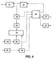
- Figure 4 shows an esquematic view of the ARF system architecture, the operation of which is similar to the PC-1000 operation (shown in Fig. 1), provided that the procedures of establishment of circuits in the selection stages are followed step by step.
- the ARF system includes, practically, the same functions, namely:
- connection to - these tracks is carried out by means of electromechanical multiplexers which are called “connecting frames" (59),each of which supports two beam tracks (60).
- connection of a marker or a recorder, active and inactive elements of the station, to a track is performed by means of multiple relays (61), which connect the signals of the level of connection of the element to the inner track of the connecting frame, having a control terminal for each multiple relay to which each element is connected.
- the coordination of the relay energizing allows the active and inactive elements to be connected.
- each of these modules would be managed by a microprocessor performing general purpose programs according to the requirements of the software architecture.
- the modules configuring the system share an interconnection network which provides communication recourses among modules, which, together with the functional character of the software system, compels it to act like an assembly of programs supported by a virtual processor.
- the digital control unit for electromechanical stations as proposed by the invention constitutes, per se, an evident novelty destined to provide a modernization and adaptation to new facilities for the user in electromechanical stations, said digital control unit being composed of hardware modules, each of which has a specific functional character.
- the digital control unit for electromechanical stations of the invention is constituted starting from an appropiate equipment sizing, which is performed in a modular manner, in accordance with the peculiar characteristics of the modernized station, so installing so many boards of every type as necessary in order to provide the mediatory elements with the electromechanical station, and to perform the functions of control, signaling and operation of communications in a station like this.
- Each hardware module is fitted with a process unit provided with microprocessor technology, controlling the signals it must transmit or record, and it is capable of performing programs of general purpose, according to the requirements of the software architecture.
- the hardware modules of the invention are equipped forming groups communicating one other through a connection network, sharing clock and communication resourses.
- PCM Pulse Code Modulation
- the network links are galvanically disconnected, the signals being transmitted in a differential mode.
- This sort of structure allows the groups to be distributed through the plant, and ensures a high noise immunity, avoiding the existence of return currents through the network links.
- the transmitting part of a link telefeeds the receiver door the output of which is galvanically disconnected.
- the modernizing equipment is a system distributed both from the control point of view, and from the equipment one.
- the functional hardware modules equipped in one group are of two types, namely:
- peripheral control modules There are two basic types of peripheral control modules, namely:
- This module also carries out the treatment of the multifrequency signalings in their different modalities, acting as a platform for the logic system of phrases.
- the functional modules of the system are organized forming groups, so that each group is fitted with a system function module (FNS), the whole equipment being complemented with peripheral control modules (MCP), until the maximum capacity thereof.
- FNS system function module
- MCP peripheral control modules
- the configuration of the peripheral control modules in the - group is determined by the requirements of their application, since the modernizing system allows any peripheral control module to be equipped in any position of the frame.
- All the modules installed in a group are fitted with a communication channel with RS232 interface.
- This communication channel with RS232 interface performs the connection of the operation terminal and the connection to the operating structure and maintenance (EOC) of the telephone network.
- All the modules are fitted with a distributed feed.
- two lines are distributed: one for feeding the control functions, i.e., the inner function of the module, and one for power functions, i.e, those related to the mediatory element working with the electromechanical system and network functions.
- the structure of feeding is distributed and disconnected, which, together with the disconnection provided by the network links, ensures the system with a high immunity in front of disturbances caused by the electromechanical generator noise on the electromechanical equipment.
- the digital control unit for electromechanical stations uses, for controlling the signal synchronism in the local network, a time base formed by three signals.
- a module FNS i.e. a function module of the system, which has a PLL (Phase Lock Loop), coupled with one of the input clocks, and it injects the generator clock into the local network.
- PLL Phase Lock Loop
- each pair Given the structure, grouped in pairs, of the system function modules, each pair generates the clock references to the next pair, there being also a duplicity of the clock signals.
- control blocks which are constituted by the following functional blocks, namely:
- the access-to-local-network element includes resourses for establishing PCM channels between the access unit to peripherals and the local network.
- connection network which provides the communication resourses, and this allows the system to increase with the only addition of the number of groups necessary to the installation.
- connection network is a multistage dynamic network connecting the PCM and statistical circuits.
- connection network is configured in a modular way starting from an only type of module, so-called “module of connection network (MRI)", which is arranged, from the switching point of view, in three functional blocks:
- module of connection network MRI
- the UAP manages the circuits placed between the system and the electromechanical elements.
- the points are of actuation and scanning nature, although there are points having only a scanning nature.
- circuits having a technology of switched sources capable of being configured as voltage and current sources with capacity for injecting or draining current (converter of four quadrants).
- the circuits configuring the mediatory elements are protected against electrical shocks, caused by the relay coils of the electromechanical elements, and also against possibly caused by metereological phenomena or of other type, in the network.
- the system has an assembly of circuits, a large part of them being of hybrid nature, which form a part of functional modules constituting the mediatory elements with the electromechanical equipment of the station.
- circuits are as follows:
- the circuit generates the loop feeding in continuous, and processes the telephone channel, performing an analog/digital conversion.
- This hybrid circuit for subscriber line carries out the intercession between the couple of subscriber and the recorder searcher, in the local chain.
- This hybrid circuit for link line processes the telephone channel, performing exclusively ananalog to digital conversion, and it is located in an output loop of the recorder searcher interface.
- this hybrid circuit for universal line performs the unhook of the link loop in those system where the electromechanical elements do not do it.
- Each functional hardware module has one or several types of wired interface boards associated, which are connected to the functional module by means of the panel of frames, which are installed and performs the following functions:
- SRE recorder signaling
- CHC connecting beam connection
- the hybrid circuits allow the electric actuation of the modules to be configured in accordance with the adequate requirements of the points in which they act.
- the SRE module structure responds to the architecture of the system modules, in which the UPSW and IARL blocks are identical for all types of modules.
- the UAP is configured by the hybrids so that it includes:
- the block of circuits of lines and links can also read the opening or closing state of the loop, which is necessary for treating the call by the electronic recorder, and also for enabling the circuits in service of out of service.
- circuits are connected to the inner PCM links of the module, so that the digital samples of the telephone channel can be switched to the connection network via the IARL, or to the signal digital processor.
- This processor is responsible for generating and detecting sigling tones, both simple and multifrequency, in the connections with the subscriber lines and with the links.
- the digital processor is controlled from the UPSW processor, which provides the necessary hardware infrastructure for treating the link and subscriber signalings.
- the signal digital processor is used, also, for generating phrases. All the modules SRE of the system give part of the RAM memory of the UPSW for storing phrases, which are transferred to the digital processor which takes on the task of including them in the inner PCM channels, from which they are injected into the corresponding analog connection.
- the PCM samples can be transferred through the connection network, and from other SRE module, and for this reason they can be generated on the corresponding connections both locally and remotely.
- the functional nature of the SRE module is completed with the corresponding PIC boards, which include, in necessary cases, the HPEX performing the voltage reading in the points of the station.
- the CHC module includes a connection with three tracks of the connecting beam, which are composed of 23 electromechanical signals of logic type.
- the UAP of this module is composed of 69 actuation and scanning points which are controlled by the corresponding HPAEs.
- This module is similar to that of SRE, although is a lot more simple due to the fact that it does not need any elements for analog connections.
- It has a PIC board associated performing the filtration of logic signals and the filtration of battery feed, and it contains the RS232 interface.
- the system completes its structure with boards performing auxiliary functions, such as:
- the alarm panel is supported by a board so-called “module of alarms and supervision of protections " (MASP).
- MASP module of alarms and supervision of protections
- Said module of alarms and upervision of protection board is generally fitted on the feeding and supervision frame, although it can also be fitted in the functional frames.
- the feeding and supervision (CAYS) frame allows the feed to be distributed to the functional frames, and it contains the alarm panel and the miscellaneous functions.
- the feed distribution to the functional frames is carried out from the system battery, through a main disjunctor, fuses, and individual dividers for each frame.
- the feed distribution to the frames is performed in an independent way for the control and power circuits.
- the alarm and miscellaneous function panel provides connecting bases for the following functions:
- the digital control unit for electromechanical stations works under environmental conditions, without using vent equipment, the equipment being cooled by natural convection, since it includes, in addition to the design of the functional modules with a lower thermal resistance (lower than 0,1 degree/watt), a high output in the power circuits.
- the last is added by a laminar ventilation which is attained by means of a special arrangement of the power circuits on the boards, and thru the existence of air deflecting panels located at the bottom of the frame, which direct the heat produced by the frame to the exterior, without affecting the frame located at the back side.
- All the electronic elements of the digital control unit for electromechanical stations are designed so that they can coexist, in a same installation, with the electromechanical elements which are replaced by them.
- the installation program is carried out in a gradual way.
- This feature is based on the properties of the functional modules of the digital control unit for electromechanical stations.
- the electronic recorder carries out the treatment of the subscriber and link signaling and the establishment control of the call, replacing the electromechanical control unit, and coordinating the activities of the rest of the subsystems, and it has two interaction types with the electromechanical equipment, namely:
- Recorder searcher allowing the subscriber and link signaling to be acceded,there being a metallic access to the physical couples of these telephone circuits.
- the electromechanical system allows the electromechanical system to be controlled, as, by means of a wire assembly, an inner signaling is performed with the electromechanical system, by using potentials or a multifrequency signaling R2.
- the establishment of physical circuits through the electromechanical connection network requires an exchange of marking and category codes or states between the electronic recorder and the station markers, this transfer controlling the recorder searcher.
- the digital control unit for electromechanical stations equip so many connections for recorder searcher as electromechanical recorders are installed in the station to be modernized.
- connecting beam tracks there are communication tracks between the control unit and the rest of the electromechanical system, Malawi a bus structure, so-called "connecting beam tracks”.
- connection to these tracks is made by means of electromechamical multiplexeers so-called "connecting frames", each of which supports two beam tracks or buses.
- the marker or recorder connection which are the active and inactive elements of the station, to a bus is performed by means of multiple relays connecting the level signals of connection of the element to the inner track of the connecting frame, having a control terminal for each multiple relay to which this element is connected.
- the coordination of the relay energizing allows a connection between active and inactive elements.
- the electronic recorder is fitted with connection functions to the connecting beams by elements so-called "track interface” (ICHC),
- Each of these connections include the data transfer terminals and the actuation control terminals of the two multiple relays of the couple of beams.
- the multiple relays are used for configuring the access to the tracks, and, therefore, they are activated permanently. So, two ICHC are associated to two tracks, and an additional ICHC is fitted per beam as stanby.
- the access to a track from any recorder is performed thru the ICHC interface corresponding to it.
- the access commands to the information transferred via the track is accessible from any recorder by means of a message among processes, and this allows to considerably reduce the number of necessary connections, and, also, multiple levels of access to the recorders are provided, by improving thereby the availability of same, and, furthermore, the increase of the number of activations of the relays improves the functional performance of the system and reduces the failure rate of same.
- the subscriber identity system provides a physical identity referred to the number of the calling subscriber equipment.
- the digital control unit for electromechanical stations performs functions of coding-and subscriber identity reading starting from - the electromechanical information of the subscriber level, within the frame of terminal selectors of the corresponding thousand and of the identity of the terminal selector frame (also denominated "frame of fifty").
- the levels of subscriber and frame of terminal selectors are multiplexed, so that, when a line marker is taken, the mutual exclusion circuit makes possible that, on the multiplexed wires, the level and the frame corresponding to the subscriber, at that time being serviced by the marker, will be only those activated.
- the subscriber identity subsystem limits itself to read the physical identity of the subscriber, and to process it in accordance with the call functional character.
- the subscriber identity subsystem is organized so that each thousand element has an encoder associated with the information provided by the electromechanical equipment, related to the subscriber identity.
- This information is processed by the encoders, which transfer it to the subscriber identification subsystem by means of a communication network which is specific of this subsystem.
- the subscriber identity subsystem receives the messages sent by an encoder, so generating an information which corresponds to the subscriber management, measures and statistics of line markers.
- the subscriber identity subsystem performs operation and maintenance functions for the subscriber's identification.
- the default recorder subsystem includes maintenance functions related to the elements identification, in particular:
- the mechanism detecting defaults is triggered by the active elements of the station, so that when an active element detects a fault, it cause a call to the default recorder, and it indicates the rest of inactive elements, involved in the call, to connect, they must connect with Said recorder.
- this recorder resolved the call concurrence, i.e. it pays only attention to one of them, the rest resting free, it rectifies the elements involved in the call, and it sends the information to the operation terminal.
- connection to the default recorder is made through an inner connection network, and in this case, the information on the default, both thru connection and as active or inactive element, is transferred by a message containing a detailed information about the default.
- This structure allows to eliminate the electromechanical connection with the existing default locator in the electromechanical recorder, generating, furthermore, a more detailed information.
- the treatment of the ill-intentioned call is performed thru the modules of the identity searcher and ill-intentioned call adaptor, and when a subscriber with category of ill-intentioned call identification provokes this process, the default recorder receives the identity of the calling subscriber provided by the identity searcher.
- the ill-intentioned call adaptor provides the default recorder with the called subscriber identity, and the data corresponding to the callling and called subscriber are processed by the default recorder, and transferred to the operation terminal.
- the calling subscriber identity is sent forward by the electronic recorder, by request of the destination station.
- the physical connection between the electromechanical equipment and the default recorder is performed thru an intermediate default distributor which performs, by means of the multiplexing on the panel, the concentration of terminals in the interface of the default recorder.
- the subsystem of link and feeder supervision manages the scanning on the output links and feeders, and it becomes it necessary for carrying out a detailed tariff and traffic measures.
- the digital control unit for electromechanical station is fitted with a connection for each output link or feeder, which determines the intake and accupation in phase of link conversation.
- connections are groupped in blocks, which are serviced by a same hardware board, i.e. a SRE module supporting 64 links.
- the equipment of this function is performed by dimensioning the number of boards according to the number of output links and feeder to be supervised.
- the treatment of the call is performed in a coordinate way by the electronic recorder and the supervision subsystem of links and feeders, so that, in phase of establishment, the responsible for the call control is the electronic recorder, this control passing to the supervision subsystem of links and feeders in the conversation phase.
- the massive storage subsystem is shaped by a processor and hard disk of commercial technology, equipped in FNS modules, which are installed in pairs, ensuring the reability and capacity which are necessary for storing and reading the following types of files:
- the files are written according to the information generation thru the calls, and they are read from te operation terminal for being transferred to the SRDF (billing data collecting system).
- SRDF billing data collecting system
- the traffic measure files have a similar process, although in this case they are transferred to SGT (traffic management system).
- the operation files can be modified both by the own system, and by the operator.
- the operation data are altered as a consequence of automatic reconfigurations of the system, and the operator can consult the operation data, either from the terminal of local operation, or from a terminal of the EOC (operation and maintenance structure).
- the subsystem of the operation terminal is composed of one or several intellingent terminals, type PC or work station, and a packet of programs supporting the operation application.
- the physical connection of the operation terminal to the switching equipment of electromechanical station modernization is performed by means of two or more RS232 interfaces, from which all the boards are fitted with, so having also a direct connection with the operation and maintenance structure which allows it to accede to the operation of the system, independently of the state of the local operation terminal.
- Figure 1 shows a schematic illustration of the architecture of an electromechanical system, exactly a PC-1000 station, where the elements composing the call establishement are detailed.
- Figure 2 shows a detail of the electromechanical system control unit, exactly a PC-1000 station according to the schematic view of Fig. 1.
- Figure 3 shows a diagram of the call stage of an electromechanical system, according to the schematic view of Fig. 1.
- Figure 4 shows the architecture of an ARF system, illustrating the differences it exhibits as regard the PC-100 system shown in Fig. 1, 2 and 3.
- Figure 5 shows the architecture of a crossed bar system, which - includes the digital control unit which replaces the control unit shown in Figs. 1, 2 and 3, so fitting the system with new facilities, which are the subject of this invention.
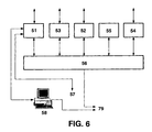
- Figure 6 shows the functional architecture of the digital control unit for electromechanical stations, with a detail of the functional modules composing it.
- Figure 7 is a detail of the connection of the connecting beam - tracks of the PC-1000 system.
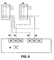
- Figure 8 shows the connection of the electronic recorder to the connecting beam tracks, once the system has been transformed including the digital control unit of the invention.
- FIG. 9 details the structure of the subscriber identity subsystem.
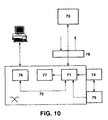
- Figure 10 shows the default recorder subsistem and its connections.
- Figure 11 corresponds to the general hardware architecture of the digital control unit, showing the connections with the interior and the own interconnection network.
- Figure 12 shows the structure of a group configuring the digital control unit.
- Figure 13 details the structure of the interconnection network.
- Figure 14 shows a schematic view of a functional module, with a detail of the elements composing it.
- Figure 15 describes the feeding distribution to the functional modules.
- FIG 16 shows, lastly, a block diagram corresponding to the electronic recorder module (SRE).
- Figure 5 shows the architecture of a crossbar system, including the digital control unit of the invention.
- the actuation in all these elements is governed upon incorporating the object of the invention, thru the digital control unit - (47), which shows an outlet digital link (48) and a connection with the operation and maintenance structure (EOC), and other one for the operation terminal (50) which, in turn, can be connected to the operation and manintenance structure (EOC), or to other network management systems, such as it can be the billing data - recording system (SRDF) or the traffic management system (SGT).
- EOC operation and maintenance structure
- EOC operation terminal
- EOC operation and manintenance structure
- other network management systems such as it can be the billing data - recording system (SRDF) or the traffic management system (SGT).
- the digital control unit for electromechanical stations (47) displays mediatory elements with the electromechanical elements, on which it acts, allowing the call be estalished, and increasing the functional character of the electromechanical station.
- the digital control unit is organized in functional modules, as shown in Fig. 6.
- These functional modules are as follows, namely:
- the signaling and control resources allow the subscriber and link signaling to be treated, as well the interaction with the electromechanical system, for establishing a call, and these functions replace the electromechanical control unit of the stations to be modernized.
- the electronic recorder (51) performs a treatment of the subscriber and link signaling and the call establishement control, replacing the electromechanical control unit, coordinating the activities of the rest of subsystems, and it has two interaction types with the electromechanical equipment.
- the establishment of the physicak circuits through the electromechanical connection network requires an exchange of the marking and category or state codes between the electronic recorder and the station markers, this transfer being performed via the recorder - searcher.
- the digital control unit for electromechanical stations equip so many connections for recorder searchers as electromechanical recorders installed in the station to be modernized.
- Figure 8 shows the connection of the electronic recorder to the - connecting beam tracks, in this case the electronic recorder (62), which modifies the control elements of the electromechanical system, and since all the recorders belong to a same digital control system, the access concurrency is solved at a logic level.
- the electronic recorder (62) is fitted with functions of connections to the connecting beams (63) by means of elements so-called "track interface” (ICHC) (64).
- IRC track interface
- Each of these connections includes the data transfer terminals and the actuation control terminals of the two multiple relays of the beam couple.
- the multiple relays are used for configuring the tracks, and,- therefore, are excited in a permanent way.
- two track interfaces (64) are associated to two tracks (65), and one additional track interface (64) is equipped per beam in stanby.
- the access commands and the information tranferred via a track is accessible from any recorder by means of a message amongst processes and this allows the number of necessary connections to be considerably reduced, and in turn it provides multiple access levels to the recorders, so improving the availability thereof.
- the reductions in the number of the relay excitations improve the functional performance of the system, and reduces the failure rate of same.
- Figure 9 shows both the connection and the functions of the subscriber identity subsystem (66), which provides the physical identity, referred to the number of equipment of the calling - subscriber.
- the digital control unit for electromechanical stations performs coding and subscriber identity reading functions starting from the subscriber level electromecanical information, within the frame of terminal selectors (68) of the corresponding thousand and of the identity of the terminal selector frame (also so-called "fifty frame").
- both the subscriber levels and the terminal selector frame are multiplexed (68), so that when a line marker is taken, the mutual exclusion circuit causes that, on the multiplexed wires, there appearing only activated the level and the frame corresponding to the subscriber at that time being serviced by the marker, and this information is read and coded by each thousand element (68).
- the subscriber identity subsystem (66) is so organized that each thousand element has an encoder associated (69) with the information provided by the electromechanical equipment, in relation to the subscriber identity.
- This information is processed by encoders (69), which transfer it to the subscriber identification subsystem (66) by means of a commumications network (70), specific in this subsystem.
- the subscriber identity subsystem (66) receives the messages sent by the encoder (69), so generating the information corresponding to the management of subscribers, measures and characteristics of the line markers.
- the default recording subsystem is shown in Fig. 10, and it includes the maintenance functions related to the identification of elements, specifically:
- the mechanism detecting defaults is trigged by the active elements of the station, so that when an active element detects a default, it provokes a call to the default recorder, and advises the rest of inactive elements involved in the call, they must connect to said recorder.
- connection to the default recorder (71) is made through the inner connection network, and, in this case, the default information, both of connection and as active or inactive element (73), is transferred by - means of a message containing a detailed information about the default.
- This structure allows the electromechanical connection to be eliminated with the existing default detector in the electromechanical recorder, a more detailed information being generated.
- the treatment of the ill-intentioned call is performed thru the modules of the identity searcher (74) and ill-intentioned call adapter (75).
- the dafault recorder (71) receives the identity information of the calling subscriber which - provides it the identity searcher (74).
- the ill-intentioned call adapter (75) provides the default recorder (71) with the identity of the called subscriber.
- the data corresponding to the calling and called subscriber - identity are processed by the default recorder (71), and transferred to the operation terminal (76).
- the calling subscriber identity is sent forward by the electronic recorder (77), at the request of the destination station.
- the physical connection between the electromechanical equipment and the default recorder is performed thru the default intermediary distributor (78), which, through multiplexing on the panel, performs a concentration of terminals at the default recorder interface.
- Said figure shows also the link and feeder supervision subsystem (54) managing the scanning on the output links and feeders, and this becomes necessary for obtaining a detailed tariff and traffic measures.
- the supervision subsystem performs the following functions:
- the digital control unit for electromechanical stations of the invention is fitted with a connection for each output link or feeder, which determine the intake and occupation in phase of link conversation.
- connections are grouped in blocks, which are served by a same hardware board, which is a SRE supporting 64 links.
- the equipment of this function is performed by dimensioning the number of boards according to the number of output links and feeders to be supervised.
- the treatment of the call is performed in a coordinate way by the electronic recorder (51), and by the link and feeder supervision subsystem (54), so that, in phase of establishment, the responsible for the call is the electronic recorder (51), this control being passed on to the link and feeder supervision subsystem (54), in the stage of conversation.
- the subsystem of massive storage (55) is composed of a processor and hard disk of commercial technology, which are installed in pairs,
- the files are written according to the generation of information by calls, and they are read from the operation terminal (58) for being transferred to the SRDF (79), that is to say, to the billing data collecting system.
- the traffic measure files display a similar process, although in this case they are transferred to the traffic management system (SGT) (79).
- SGT traffic management system
- the operation files can be modified, both by the own system and by the operator.
- the operation data are altered as a consequence of the automatic reconfiguration of the system.
- the operator can consult the operation data, either from the local operation terminal (58), or from a terminal of the operation and maintenance structure (EOC) (57).
- EOC operation and maintenance structure
- the operation terminal subsystem (58) is composed of one or several intelligent terminals, workstation or PC type, and also by packet of programs which supports the application of the operation.
- the physical connection of the operation terminal to the switching equipment for modernizing electromechanical stations is performed by means of two RS232 interfaces, of which all the boards are fitted with, so having also a direct connection with the EOC, that is to say, with the operation and maintenance structure (57), which allows it to accede to the operation of the system, independently of the state of the local operation terminal.
- this architecture is shown in Fig. 11.
- the hardware modules of the system are fitted forming groups (80) which communicate thru the interconnection network (81), sharing clock (82) and communication resources.
- the communication amongst system modules is performed by means of channels PCM (Pulse Code Modulation), and statistical channels, there being two links (83) of communication between each group (80) and the interconnection network (81).
- PCM Pulse Code Modulation
- statistical channels there being two links (83) of communication between each group (80) and the interconnection network (81).
- the network links (83) are galvanically disconected, the signals being transmitted in a differential mode.
- This structure allows the groups to be distributed in a plant, and it ensures a high noise immunity, avoiding the existence of return current through the network links (83).
- the transmitting side of a link telefeeds at the receiver door, the output of which is disconnected galvanically.
- the modernizing equipment is a system distributed both from the control point of view and from an equipment point of view.
- each group is composed of hardware modules which communicate by means of local network (85).
- the local ntework (85) displays statistical links (86), type PCM links (87) and clock and synchronism signals (88).
- the functional hardware modules equipped in a group are of two types, namely:
- MCP peripheral control module
- the functionsl modules of the system are organized forming groups, so that each group is equipped with a module FNS (89), the equipment being completed with modules MCP (90), up to the maximum capacity of this.
- the configuration of the modules MCP (90) in the group is determined by the requirements of application, since the modernizing system allows any module MCP (90) to be equipped in any position in the frame.
- the equipment dimensioning is carried out in a modular way, in accordance with the characteristics of the modernized station, by installing as much boards of each type as necessary in order to manage the mediatory elements (91) with the electromechanical sta - tion and carry out the functions of control, signaling and operation of the communications in a station of this type.
- Each hardware module is fitted with a process unit implemented with a microprocessor technology, which performe the control of the signals to be transmiited or recorded, and it can perform general purpose programs, according to the requirements of the software architecture.
- All the modules installed in a group are fitted with a communications channel with RS232 interface.
- This communications channel performs the connection of the operation terminal and the connection to the operation and maintenance structure (EOC) of the telephone network.
- EOC operation and maintenance structure
- the communication by means of the interconnection network is established.
- the interconnection network is a dynamic multistage network which allows to communicate amongst system elements by means of PCM links and statistical links.
- the network is configured in a modular manner through a sole type of module so-called “interconnection network module” (MRI).
- MRI interconnection network module
- the module of the interconnecting network is structured from the switching point of view in three functional blocks, namely:
- the two types of network link(97) coexist: those of type PCM (95), and statistical type (96).
- the digital control unit for electromechanical stations uses, for controlling the signal synchronism in the local network, a time base composed of three signals.
- FNS frequency division multiplexer
- PLL phase lock loop
- each pair Due to the structure, groupped in pairs, of the FNS modules, each pair generates the clock references to the next pair, there being always a duplicity of clock signals.
- the architecture of the hardware modules of the system is unified in relation to the control blocks, and as the Fig. 14 shows, they are constituted by the following functional blocks:
- This process unit is formed by a CPU (99), a RAM memory (100), an EPROM memory (101), a memory management unit (102), a physical address (103) and a peripheral management unit of the system (104).
- the UAP (105) manages the circuits between the systems and the electromechanical elements (106).
- the points in general, will be points of actuation and scanning, although there are only scanning points. In case of actuation, this must answer in a dynamic way in the course of the operations to be carried out, which is attained with the inclusion, in the technology circuits, of switched sources which can be configured as voltage and current sources with capacity for injecting or draining current (four-quadrant converter).
- the circuits configuring the mediatory elements are protected against electrical shocks caused by the relay coils of the electromechanical - elements, as well as those capable of being caused by metereological phenomena or other type in the network.
- the incorporated protections are materialized in gas dischargers and semiconductor devices, as well asagainst short-circuits in the low voltage power distribution.
- the invention has a circuit assembly, mainly of hybrid nature, forming a part of the functional modules, which constitute the mediatory elements with the electromechanical equipment of the station.
- It includes, furthermore, a facility in digital programming and digital read of the voltage and current levels at the output, for the actuation and scanning points it manages, and which are found in the station.
- the circuit generates the loop feed in a continuous mode, and it processes the telephone channel, so performing an analog-digital conversion.
- This HCLA circuit mediates between the subscriber pair and the recorder searcher, in the local chain.
- Fig. 15 illustrates the feed distribution to the hardware modules.
- two lines are distimped: one for feeding the control functions (111), that is to say, the inner functions to the module arriving thru a converter (112), until the control circuits (113) of the module.
- the other line is the power line (114), and serves to power functions (115), that is to say, the relationships with the management of the mediatory elements (116) with the electromechanical system and network functions.
- the feed structure is distributed and disconnected, which, united to the disconnection provided by the network links, ensures the system with a high immunity in front of disturbances caused by the electromagnetic noise generated in the electromechanical equipment.
- Each hardware functional module has one or several types of boards of PIC wiring interface associated, connected to the functional module by means of the frame panels where the following functions are installed and performed:
- This switch connects the pair terminals to a HPAE circuit, or a line or link circuit.
- the hybrid circuits allow the electric actuation of the modules in accordance with the requirements peculiar of the points in which - they act, to be configured.
- the structure of the SRE module is shown in Fig. 16, and it answers to the architecture of the system modules, in which the UPSW (117), and IARL (118) blocks are identical for all the types of modules, the UAP (119) being conformed by the hybrids, so that it includes:
- the line and link circuit block can also read the opening or closing state of the loop, necessary for treating the call by the electronic recorder, as well as enabling the circuits so that all are in service or out of service.
- circuits are connected to the PCM inner links of the module (123), so that the digital samples of the telephone channel can be switched towards the connection network thru the IARL (118), or towards the signal digital processor (124).
- the signal digital processor (124) is responsible for generating and detecting tones of signaling, both simple and multifrequencies, on the connections with the subscriber lines and the links, the signal digital processor (124) being, in turn, controlled from the UPSW (121) processor, so providing the necxessary hardware infrastructure for treating the subscriber and link signalizing.
- the signal digital processor (124) is also used for generating locutions, and all the SRE modules of the system devote a part of the memory RAM of the UPSW (117) to storing locutions, these being transferred to the signal digital processor (124), which takes on the task of include them in inner PCM channels (123), from where they are injected to the corresponding analog connection.
- the PCM samples can be transferred thru the connection network of the IARL (118), and from other SRE module, for which reason they can be generated on the corresponding connections, both locally and remotely.
- the control feed of the UAP circuits (119) is performed by means of a DC/DC converter (125).
- the UAP characteristics (119) allow the module SRE to be utilized in differect actuation points.
- the functional character of the SRE module is completed with the corresponding PIC boards (126), which include, in necessary cases, the HPEX performing the voltage reading in points of the station.
- the CHC module includes a connection with three connecting beam connection, which are composed of 23 electromechanical signals of logic type.
- the UAP of this module is composed of 69 actuation and scanning points, which are managed by the corresponding HPAEs.
- the system completes its structure with boards performing auxiliary functions, such as:
- the alarm panel is supported by a board so-called “module of alarms and supervision of protections” (MASP).
- MASP module of alarms and supervision of protections
- This board is fitted, in general, on the feeding and supervision frame, although it can be placed also in the functional frames.
- the feeding and supervision frame (CAYS) allows the feed to be distributed to the functional frames, and it contains the alarm - panel and the miscellaneous functions.
- the distribution of the feeding to the functional frames is - performed from the system battery, thru a general or main disjunctor, fuses, and individual dividers per each frame.
- the distribution of the feeding to the frames is performed in an independent manner for the control and power circuits.
- the panel of alarms and miscellaneous functions provides bases of connector for the following functions:
- the digital control unit for electromechanical stations works under environmental conditions without using ventilation equipment, the equipment being cooled by natural convection, since, in addition to the very low thermal resistance functional modules (lower than 0.1 degree/watt), it includes a high performance in the power circuits.
- All the electronic elements of the digital control unit for electromechanical stations are designed so that they can coexist, in a same installation, with the electromechanical elements to which they replace.
- the installation process is carried out in a progressive way, and this feature is based on the properties of the functional modules of the digital control unit for electromechanical stations.
Landscapes
- Engineering & Computer Science (AREA)
- Databases & Information Systems (AREA)
- Computer Networks & Wireless Communication (AREA)
- Exchange Systems With Centralized Control (AREA)
- Control By Computers (AREA)
- Power Sources (AREA)
- Programmable Controllers (AREA)
- Selective Calling Equipment (AREA)
- Feedback Control In General (AREA)
Applications Claiming Priority (2)
| Application Number | Priority Date | Filing Date | Title |
|---|---|---|---|
| ES09500663A ES2109869B1 (es) | 1995-04-03 | 1995-04-03 | Unidad de control digital para centrales electromecanicas. |
| ES9500663 | 1995-04-03 |
Publications (2)
| Publication Number | Publication Date |
|---|---|
| EP0737017A2 true EP0737017A2 (de) | 1996-10-09 |
| EP0737017A3 EP0737017A3 (de) | 2000-01-12 |
Family
ID=8289993
Family Applications (1)
| Application Number | Title | Priority Date | Filing Date |
|---|---|---|---|
| EP96500032A Withdrawn EP0737017A3 (de) | 1995-04-03 | 1996-03-13 | Digitales Steuergerät für elektromechanische Fernsprechvermittlungsstellen |
Country Status (8)
| Country | Link |
|---|---|
| EP (1) | EP0737017A3 (de) |
| AR (1) | AR001419A1 (de) |
| BR (1) | BR9600630A (de) |
| CO (1) | CO4370138A1 (de) |
| ES (1) | ES2109869B1 (de) |
| MA (1) | MA23805A1 (de) |
| PE (1) | PE48197A1 (de) |
| UY (1) | UY24169A1 (de) |
Family Cites Families (6)
| Publication number | Priority date | Publication date | Assignee | Title |
|---|---|---|---|---|
| FR2259507B1 (de) * | 1974-01-24 | 1980-01-18 | Cit Alcatel | |
| FR2357124A1 (fr) * | 1976-06-29 | 1978-01-27 | Brosseron Jean | Dispositif d'analyse de donnees numeriques a commande externe et interne de calculateur |
| IT1128782B (it) * | 1980-05-05 | 1986-06-04 | Cselt Centro Studi Lab Telecom | Dispositivo per l acquisizione di criteri telefonici da organi di centrali elettromeccaniche |
| FR2511827A1 (fr) * | 1981-08-21 | 1983-02-25 | Desprez Pierre | Carte d'interface pour le calibrage et la selection de donnees saisies dans un central telephonique electromecanique |
| ATE210915T1 (de) * | 1991-07-31 | 2001-12-15 | Siemens Ag | Verfahren zur änderung von systemkonfigurationsdatensätzen in einem fernmeldevermittlungssystem |
| BR9401344A (pt) * | 1994-03-23 | 1995-10-24 | Da Costa Ribeiro Neto Af Feijo | Controle digital para centrais analógicas |
-
1995
- 1995-04-03 ES ES09500663A patent/ES2109869B1/es not_active Expired - Fee Related
-
1996
- 1996-02-13 MA MA24161A patent/MA23805A1/fr unknown
- 1996-02-14 CO CO96006892A patent/CO4370138A1/es unknown
- 1996-02-16 UY UY24169A patent/UY24169A1/es not_active Application Discontinuation
- 1996-02-27 BR BR9600630A patent/BR9600630A/pt active Search and Examination
- 1996-03-13 EP EP96500032A patent/EP0737017A3/de not_active Withdrawn
- 1996-03-25 AR AR33589796A patent/AR001419A1/es unknown
- 1996-03-27 PE PE1996000216A patent/PE48197A1/es not_active Application Discontinuation
Also Published As
| Publication number | Publication date |
|---|---|
| PE48197A1 (es) | 1997-11-29 |
| BR9600630A (pt) | 1997-12-30 |
| CO4370138A1 (es) | 1996-10-07 |
| ES2109869B1 (es) | 1998-08-01 |
| AR001419A1 (es) | 1997-10-22 |
| ES2109869A1 (es) | 1998-01-16 |
| EP0737017A3 (de) | 2000-01-12 |
| UY24169A1 (es) | 1996-07-23 |
| MA23805A1 (fr) | 1996-10-01 |
Similar Documents
| Publication | Publication Date | Title |
|---|---|---|
| EP0161031B1 (de) | Fernmeldesystem, insbesondere Fernsprechsystem | |
| US4791640A (en) | Call charging arrangement | |
| JPH0630776Y2 (ja) | エレベータ設備の遠隔管理装置 | |
| CA1243759A (en) | Information transport system | |
| CA1331802C (en) | Modularly structured digital communications system having operations-oriented and security-oriented components | |
| PL183244B1 (pl) | Sposób przetwarzania komunikatów sygnalizacyjnych w stacji przekazywania sygnałów i w systemie telekomunikacyjnym zawierającym stację przekazywania sygnałów | |
| CA1319442C (en) | Applications processor for a craft access system | |
| US4866700A (en) | Digital switching system | |
| US3597544A (en) | Data switching system | |
| EP0737017A2 (de) | Digitales Steuergerät für elektromechanische Fernsprechvermittlungsstellen | |
| US4351049A (en) | Circuit arrangement for user stations in a communications network | |
| KR100196716B1 (ko) | 교환기내의 통신망 연동을 위한 공통선 메세지변환방법 | |
| CA1194189A (en) | Remote data link switching arrangement | |
| KR940008780B1 (ko) | 전전자 교환기의 No.7 공통선 신호방식 처리 장치 | |
| KR100335693B1 (ko) | 공통선 신호 망에서의 중계선 용량을 증대시킬 수 있는 교환기 | |
| KR100208963B1 (ko) | 국설 전전자 교환기의 rasm구조 | |
| US3410962A (en) | Multiselectors employing crossbar switches having split horizontals or selection levels | |
| Crawford et al. | Common channel interoffice signaling: 4A toll crossbar Application | |
| Kunze | Large systems: EWS: Germany's answer to ESS: Stored-program control is at the heart of the Deutsche Bundespost's electronic telephone switching system | |
| KR960009462B1 (ko) | 원격 교환 장치 | |
| Joel | Communication switching systems as real-time computers | |
| US2230053A (en) | Telephone system | |
| KR100247418B1 (ko) | 전전자 교환기의 국간 선로 시험을 위한 패스 연결 방법 | |
| KR19980016046A (ko) | Tdx-10계열 교환기의 호처리장애시 원격교환모듈의 단독기능수행방법 | |
| US3238311A (en) | Switching system test circuit |
Legal Events
| Date | Code | Title | Description |
|---|---|---|---|
| PUAI | Public reference made under article 153(3) epc to a published international application that has entered the european phase |
Free format text: ORIGINAL CODE: 0009012 |
|
| AK | Designated contracting states |
Kind code of ref document: A2 Designated state(s): CH DK FR GB GR IT LI PT |
|
| PUAL | Search report despatched |
Free format text: ORIGINAL CODE: 0009013 |
|
| RIC1 | Information provided on ipc code assigned before grant |
Free format text: 7H 04Q 3/42 A, 7H 04Q 3/545 B |
|
| AK | Designated contracting states |
Kind code of ref document: A3 Designated state(s): CH DK FR GB GR IT LI PT |
|
| RAP1 | Party data changed (applicant data changed or rights of an application transferred) |
Owner name: TELEFONICA, S.A. |
|
| STAA | Information on the status of an ep patent application or granted ep patent |
Free format text: STATUS: THE APPLICATION HAS BEEN WITHDRAWN |
|
| 18W | Application withdrawn |
Withdrawal date: 20000215 |