EP0737112B1 - Systeme de tri de dechets metalliques - Google Patents
Systeme de tri de dechets metalliques Download PDFInfo
- Publication number
- EP0737112B1 EP0737112B1 EP95907243A EP95907243A EP0737112B1 EP 0737112 B1 EP0737112 B1 EP 0737112B1 EP 95907243 A EP95907243 A EP 95907243A EP 95907243 A EP95907243 A EP 95907243A EP 0737112 B1 EP0737112 B1 EP 0737112B1
- Authority
- EP
- European Patent Office
- Prior art keywords
- image
- conveyor
- viewing area
- cell
- particles
- Prior art date
- Legal status (The legal status is an assumption and is not a legal conclusion. Google has not performed a legal analysis and makes no representation as to the accuracy of the status listed.)
- Expired - Lifetime
Links
Images


Classifications
-
- B—PERFORMING OPERATIONS; TRANSPORTING
- B07—SEPARATING SOLIDS FROM SOLIDS; SORTING
- B07C—POSTAL SORTING; SORTING INDIVIDUAL ARTICLES, OR BULK MATERIAL FIT TO BE SORTED PIECE-MEAL, e.g. BY PICKING
- B07C5/00—Sorting according to a characteristic or feature of the articles or material being sorted, e.g. by control effected by devices which detect or measure such characteristic or feature; Sorting by manually actuated devices, e.g. switches
- B07C5/34—Sorting according to other particular properties
- B07C5/342—Sorting according to other particular properties according to optical properties, e.g. colour
- B07C5/3422—Sorting according to other particular properties according to optical properties, e.g. colour using video scanning devices, e.g. TV-cameras
-
- B—PERFORMING OPERATIONS; TRANSPORTING
- B07—SEPARATING SOLIDS FROM SOLIDS; SORTING
- B07C—POSTAL SORTING; SORTING INDIVIDUAL ARTICLES, OR BULK MATERIAL FIT TO BE SORTED PIECE-MEAL, e.g. BY PICKING
- B07C5/00—Sorting according to a characteristic or feature of the articles or material being sorted, e.g. by control effected by devices which detect or measure such characteristic or feature; Sorting by manually actuated devices, e.g. switches
- B07C5/36—Sorting apparatus characterised by the means used for distribution
- B07C5/363—Sorting apparatus characterised by the means used for distribution by means of air
- B07C5/367—Sorting apparatus characterised by the means used for distribution by means of air using a plurality of separation means
- B07C5/368—Sorting apparatus characterised by the means used for distribution by means of air using a plurality of separation means actuated independently
-
- G—PHYSICS
- G06—COMPUTING OR CALCULATING; COUNTING
- G06V—IMAGE OR VIDEO RECOGNITION OR UNDERSTANDING
- G06V10/00—Arrangements for image or video recognition or understanding
- G06V10/40—Extraction of image or video features
-
- Y—GENERAL TAGGING OF NEW TECHNOLOGICAL DEVELOPMENTS; GENERAL TAGGING OF CROSS-SECTIONAL TECHNOLOGIES SPANNING OVER SEVERAL SECTIONS OF THE IPC; TECHNICAL SUBJECTS COVERED BY FORMER USPC CROSS-REFERENCE ART COLLECTIONS [XRACs] AND DIGESTS
- Y10—TECHNICAL SUBJECTS COVERED BY FORMER USPC
- Y10S—TECHNICAL SUBJECTS COVERED BY FORMER USPC CROSS-REFERENCE ART COLLECTIONS [XRACs] AND DIGESTS
- Y10S209/00—Classifying, separating, and assorting solids
- Y10S209/938—Illuminating means facilitating visual inspection
-
- Y—GENERAL TAGGING OF NEW TECHNOLOGICAL DEVELOPMENTS; GENERAL TAGGING OF CROSS-SECTIONAL TECHNOLOGIES SPANNING OVER SEVERAL SECTIONS OF THE IPC; TECHNICAL SUBJECTS COVERED BY FORMER USPC CROSS-REFERENCE ART COLLECTIONS [XRACs] AND DIGESTS
- Y10—TECHNICAL SUBJECTS COVERED BY FORMER USPC
- Y10S—TECHNICAL SUBJECTS COVERED BY FORMER USPC CROSS-REFERENCE ART COLLECTIONS [XRACs] AND DIGESTS
- Y10S209/00—Classifying, separating, and assorting solids
- Y10S209/939—Video scanning
Definitions
- the present invention relates to a system for sorting scrap particles based upon their color.
- Another limitation to the existing image processing sorting systems is the difficulty in maintaining consistent, even illumination of the viewing area through which the particles are conveyed.
- Another drawback of existing image processing sorting systems is the difficulty in maintaining a uniform contrasting background to the particles.
- Another drawback of the existing image processing sorting systems is that the efficiency of the system is affected by variations in the conveyor speed due to, for example, mechanical problems such as slippage.
- the sorter apparatus includes a conveyor, a position sensor, a lighting shroud having an image detector, means for providing constant illumination, and an image processor for analysing the colour images to identify pieces of fruit and thereafter decide, based upon colour analysis, into which category the particular piece of fruit is classified.
- One object of the present invention is to provide an improved system for sorting scrap particles as they are transported on a conveyor, which is not dependent upon the positioning of the particles on the conveyor and which can sort scrap particles having widely ranging random shapes.
- a system for sorting scrap particles based upon colour including a conveyor for conveying the scrap particles; a position sensor for determining the position of the particles on the conveyor; a lighting shroud mounted above the conveyor for providing constant, controlled illumination of different preselected wavelengths at a pre-defined viewing area along which the particles are conveyed by the conveyor; an image detector mounted within the shroud above the conveyor for acquisition of a colour image of the viewing area; an image processor for receiving from the image detector the data corresponding to an image of the viewing area, and a separator located downstream from the image detector; wherein the conveyor has a surface providing a uniformly contrasting background for the particles, the image processor includes logic for dividing the viewing area into a matrix of cells independently of the presence or absence of particles in the viewing area, wherein each cell in the matrix includes a plurality of pixels, each pixel having a digital value corresponding to the image acquired by the image detector, the image processor further including a resultant array of memory locations corresponding
- a computer-implemented method for sorting randomly shaped scrap particles as they are conveyed in random locations on a moving conveyor through a pre-defined viewing area including the steps of acquiring data corresponding to an image of the viewing area; dividing the viewing area into a matrix of cells, each cell including a plurality of pixels,defining a resultant array of memory locations corresponding to the total number of pixels in the image, each pixel having a digital value corresponding to the image acquired; defining a discriminator signal array of memory locations corresponding to the total number of cells in the matrix; determining for each pixel, independently of the presence or absence of particles in the viewing area, whether the value in that pixel satisfies a predetermined colour criteria and setting a value in the location in the resultant array corresponding to that pixel as a function of the colour criteria determination; determining for each cell whether the values in the resultant array corresponding to pixels in that cell satisfies a predetermined separation criteria; setting a
- the system may also include a wetting device mounted upstream from the image detector for wetting the surface of the conveyor, thereby creating a more uniform background for the acquired images.
- the system may also include a plurality of conveyor sections located along the length of the conveyor upstream from the image detector, wherein each of the sections convey the particles at progressively increasing speeds, thereby progressively separating the scrap particles from each other in the direction of conveyance to provide for a more efficient processing of the acquired images.
- the image detector comprises an RGB colour, broadcast quality CCD camera.
- a lighting shroud which is illuminated by a plurality of fluorescent lights with diffuser panels interposed between the lights and the viewing area, provides constant, controlled illumination of the viewing area on the conveyor.
- the image processor may perform various analyses on each of the digital pixel values recorded for an image.
- the system analyzes the digital values for each pixel to determine whether a predefined color criteria is met, then analyzes the results for the pixels in each cell of the matrix and, based upon a predetermined selection criteria, establishes a discriminator signal corresponding to each cell for output to the separator controller.
- various criteria can be utilized for determining the value of the discriminator signal, including frequency, location, and density of the identified pixels.
- the discriminator signal is merely a function of the number of pixels in that cell which satisfy the color criteria.
- the image processing function, the image detector, conveyor position sensor, and separator control functions, as well as other control functions utilized by the system, may be performed by one or more hardware control means as desired.
- the image processor is built around an Intel 80486 based CPU suitably enhanced by plug-in cards to perform image acquisition and processing, as well as data transmission functions.
- the image detector control and separator control functions are embodied in a suitably programmed programmable logic controller (PLC).
- a uniformly contrasting background may be achieved by employing a uniform color conveyor belt with a wetting device mounted over the conveyor belt upstream of the viewing area for spraying a liquid, such as water, on the moving conveyor belt.
- a liquid such as water
- the separator may comprise a plurality of spaced apart air nozzles which are selectively activated in a timed fashion to direct a jet of air onto selected scrap particles, thereby altering their trajectory as they are discharged from the conveyor belt so that the particles are selectively directed into separate bins.
- the system of the present invention thus provides an image processing system which effectively sorts randomly shaped and randomly located scrap particles as they are conveyed on a high speed conveyor. Because the image processor analyzes the images by cell, rather than attempting to locate and examine articles of a specified size or shape, processing time is greatly reduced and, therefore, conveyor speed and sorting rate greatly increased. Also, since the processor does not attempt to discriminate the individual particles, processing is not affected by the number of particles conveyed.
- the present invention can enable the provision of a system for sorting scrap particles having a wide range of reflectivity.
- the present invention can also enable the provision of an image processing scrap particle sorting system wherein the speed and efficiency of operation of the system is not affected by the number of scrap particles being sorted.
- the present invention can also enable the provision of a system for sorting scrap particles wherein the sorting accuracy of the system is not affected by variations in conveyor speed due to a mechanical problem, such as slippage.
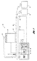
- the illustrated scrap particle sorting system in accordance with the present invention includes a conveyor 22 which conveys the randomly shaped scrap particles in a random orientation through the viewing area 24 at which a series of images are detected by an image detector 26.
- the viewing area 24 is illuminated in a uniform, controlled fashion by a lighting shroud 28.
- a position sensor 30 determines the linear advancement of the conveyor 22, and thus the advancement of the scrap particles thereon, and transmits signals indicating this advancement to an image detector controller 32.
- the image detector controller emits a control signal to an image processor 34 to acquire an image of the viewing area.
- the image processor 34 analyzes the data to determine, for each cell in a predefined imaginary matrix superimposed on the viewing area, whether the pixels in that cell satisfy a predetermined criteria. The image processor 34 then establishes a discriminator signal corresponding to each cell of the imaginary matrix. These discriminator signals are then communicated to a separator controller 36, which in a timed fashion transmits control signals to a separator 38 based upon the values of the discriminator signals to activate selective portions of the separator in a controlled fashion to eject desired from undesired particles as they are dispatched from the conveyor 22.
- the system may sort copper or brass particles from zinc particles by selectively directing the copper and brass particles into a downstream bin 45, while the zinc particles are discharged into bin 43 nearer the end of the conveyor 22.
- the lighting shroud 28 is operatively connected to a lighting control 40, which provides uniform illumination of the viewing area 24.
- the system 20 may include a wetting device 41 which extends across the width of the conveyor 22 upstream from the viewing area 24, to provide a constant spray of liquid onto the surface of the conveyor 22 to create a darkened, more uniform conveyor surface as the background.
- a wetting device 41 which extends across the width of the conveyor 22 upstream from the viewing area 24, to provide a constant spray of liquid onto the surface of the conveyor 22 to create a darkened, more uniform conveyor surface as the background.
- the conveyor 22 comprises an endless belt 42 driven by a conventional motorized head pulley 44.
- the image detector 26 employs a three chip, RGB color CCD camera such as model XC-007, available from Sony Corporation.
- the camera is mounted within the lighting shroud 28 which comprises a generally rectangular frame 46 covered on four sides by opaque panels 48.
- the position sensor 30 comprises a commercially available timing eye comprising, for example, LED part number 42SRU 6202, reflector number 92-47 and mounting plate number-60-2008, all available from Allen-Bradley Corporation.
- the LED and reflector are mounted so that the beam is alternately transmitted through and interrupted by rectangular openings 50 which are equal in length to the opaque belt spaced therebetween.
- the openings are 2.54cms (one inch) in length with 2.54cms (one inch) separation between them.
- the components of the position sensor 30 transmit a high signal to the image detector and separator controllers at the leading edge of each opening 50, and a low signal to each of the image detector and separator controllers at the trailing edge of each opening.
- the image detector controller can maintain a count of the signals received from the position sensor 30 and determine whether the accumulated. count equals the preset value corresponding to the length of the viewing area.
- the image detector controller 32 transmits a signal to the image processor to acquire another image, then clears the accumulated count to renew tracking the movement of the conveyor belt.
- the separator controller 36 can similarly maintain a count of the signals transmitted by the position sensor 30 to determine whether this accumulated count equals a preset value corresponding to the length of one row of cells in the imaginary matrix.
- the separator controller 36 can transmit the appropriate activation signals to selectively activate appropriate air blast nozzles to separate selected scrap particles located on the conveyor in positions corresponding to the cells in the next row of the matrix which have reached the discharge end of the belt. It will thus be appreciated that the image detector 26 and separator 38 can each be synchronized with the conveyed scrap particles independently of any variations in belt speed.
- the image processor is built around a conventional Intel 80486 based personal computer.
- Image acquisition and storage capability may be provided using plug-in boards such as Image-CLD and Image-1280, respectively, from Matrox Electronic Systems, Ltd.
- Computationally intensive image processing functions may be performed on an additional plug-in board of the type Image-RTP, also available from Matrox Electronic Systems, Ltd.
- Data consisting of on/off states of air valves could be transmitted to the separator controller using high speed serial data transmission interface boards such as 1784-KT, available from Allen-Bradley Corporation.
- the 80486 based PC forms the integrating platform around which these various plug-in boards may be configured, programmed, and controlled.
- the computer station 52 may include several conventional CRT screens 54-58.
- Screen 54 displays the processed image for a selected image
- screen 56 displays the unprocessed image detected by the camera
- screen 58 is the operator interface screen for the image processing computer.
- a pushbutton module 62 may also be utilized to provide the operator with often- used system control keys, and a stop button 64 is preferably located on the front panel of the computer station 52 to provide for quick deactivation of the system when desired.
- the computer station 52 also includes the image detector control 32 and separator control 36, in the form of a suitably programmed PLC (shown in outline as 35 in Figure 1).
- PLC Model No. 5/20 available from the Allen-Bradley Corporation, may be programmed to perform the two timing control functions associated, respectively, with activating the image detector and activating the separator.
- the lighting control 40 is housed within control box 66.
- the control comprises one or more light controllers associated with fluorescent bulbs in the lighting shroud 28. Coupled to each light controller is a photoelectric eye which is mounted within the lighting shroud (shown as 80 in Figure 4) which senses the illumination level within the shroud, and sends a signal to the light controllers in the light control box 66. The controllers then automatically adjust the level of illumination of the bulbs to maintain the illumination within the shroud at a predetermined level.
- Light controller Model No. FX1096, available from Mercron, Inc., in Texas, may be suitably configured to perform the function of the lighting control 40.
- the separator 38 comprises a plurality of air blast nozzles 70 disposed in an ejector plate 68 across the width of the conveyor.
- the nozzles (shown in greater detail in Figures 5 and 6) are connected to corresponding electrically actuated air valve assemblies in assembly box 72.
- the air valve assembly comprises solenoid valves, Model No. N-721, available from the Honeywell Corporation.
- the separator control function in the PLC 35 is programmed to transmit activation signals to selectively activate the appropriate valve assemblies at the appropriate time (as described in further detail hereinafter) to emit a blast of air from selected nozzles 70 at the ejector plate 68, thereby directing selected scrap particles away from the particle bin nearest the discharge end of the belt into another particle bin further downstream of the discharge end of the belt.
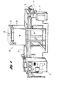
- the lighting shroud and camera assembly of the embodiment of the system 20 shown in Figures 2 and 3 includes a generally rectangular frame 46 and frame mounts 74 fabricated from suitable structural material, such as aluminum or sheet metal.
- suitable structural material such as aluminum or sheet metal.
- four General Electric No. F48T12/CWX/HO fluorescent lamps 76 are mounted in each of the side walls defined by the frame 46.
- One or more fans, such as Conair Model No. MU20A1 with suitable filters, are mounted within the shroud to remove the heat, dust and debris from the viewing area.
- a series of photoelectric eyes 80 are mounted in the side light panels, and are operably connected to the light controllers to provide a constant feedback signal indicating the level of illumination within the shroud.
- the outside of the side walls of the frame 46 are covered with opaque panels (not shown) which may be fabricated from sheet metal or other suitable material.
- the inside of the side walls are covered with light diffuser material to provide for diffuse, even lighting of the viewing area 24.
- the diffuser panels comprise 0.64cms (1/4") x 122cms (4") x 183cms (6") white acrylic sheets.
- the CCD color camera is utilized as the image detector 26, and is mounted atop the lighting shroud so that the lens of the camera projects into the illuminated area within the shroud through an opaque top panel 82.
- the separator 38 employs a plurality of air blast nozzles 70 mounted across the width of the discharge end of the conveyor 22.
- the discharge end of the air blast nozzles are connected to ejector plate 68 through spaced apart holes and are secured in place by set screws 86.
- the holes are spaced 1.27cms (one-half inch) apart across the width of the conveyor 22.
- the holes on the ejector plate 68 may be positioned so that a blast nozzle mounted therethrough is at the center of where each cell would be if one row of cells from the imaginary matrix were superimposed over the ejector plate 68.
- the system 20 of the present invention may include an article spacer 23 located upstream from the conveyor 22 for modifying the extent of separation of the scrap particles prior to depositing them on the conveyor 22.
- the article spacer 23 may include a series of endless belt conveyors 88, 90, 92, with each of the conveyors set to travel at progressively increasing speeds (to increase the relative separation of the particles in the direction of conveyance), or progressively decreasing speeds (to decrease the relative separation between the scrap particles in the direction of conveyance). It will be appreciated that by utilizing these stepped conveyors, the desired spacing can be obtained to ensure that the scrap particles are separated by a distance generally greater than the dimension of the matrix cells in the direction of conveyance, thereby minimizing the chance that more than one scrap particle is in any one cell.
- three endless belt conveyors 88, 90, 92 are shown in addition to the system's main belt conveyor 42, any number of separate conveyors may be utilized at various speed differences depending upon the desired degree of separation of the scrap particles.
- FIG. 8 illustrates the general flowchart for the camera and separator control functions.
- these control functions are both performed by a single suitably programmed PLC which obtains belt position information from the position sensor 30.
- the belt sensor 30 sends the PLC a trigger signal each time it senses the leading or trailing edge of an opening 50 on the conveyor belt 42.
- the PLC periodically checks, at 94, to determine whether the accumulated belt sensor cell trigger count is equal to a number corresponding to a length of the conveyor belt equal to the dimension of one cell. If not, the system exits the sub-routine. If so, the system clears the accumulated cell trigger count, at 96, and transmits a discriminator signal for the next row of cells in the separator control's memory queue to the blast air valves.
- the image processor sends the separator memory of the PLC a data block of binary discriminator signals corresponding to an entire image matrix of m x n cells
- the separator control logic transmits a single row of l x n discriminator signals to the air valves in a timed fashion suitable to activate the selected air valves. This data transmission is effected when the portion of the belt (and scrap particles thereon) corresponding to that particular row of cells has reached the discharge end of the conveyor 22. It will be appreciated by the previous description that, thereafter, the valve activation signals are transmitted by the separator controller in a row by row manner on the basis of the signals received by the belt position sensor 30.
- the separator control then indexes the accumulated belt sensor image trigger count, at 100, and checks to determine whether the accumulated belt sensor image trigger count is equal to the number corresponding to the length of belt covered by one image. If the belt has not yet traveled a distance equal to the length of one image, the system exits the sub-routine at 102. If the count indicates that the belt has traveled the length of one image, the system clears the accumulated image trigger count and sends a trigger signal to the image processor, at 104, to acquire another image.
- the constant monitoring of the conveyor belt movement by the PLC allows for timed dispatch of the appropriate control signals to both the separator 38 and the image processor 34.
- the image processor generates a block of on/off discriminator signals corresponding to each of the cells of the matrix superimposed on the image by the processor.
- This block of data is sent as a serial stream of size equal to one bit per cell for an entire matrix of cells covering one image.
- the data is transmitted to the separator control in the PLC, where it is queued in memory.
- These blocks of binary discriminator signal data are transmitted from the image processor asynchronously from the subsequent row by row transmission of the signals by the separator controller 36 to the separator 30.
- this asynchronous transmission of data makes the image processor available for acquisition and processing of an adjoining section of the belt prior to when the segment that has already been processed reaches the discharge end of the conveyor 22.
- the finite time interval required for the receipt of the data does not influence the processing time of the PLC since it can receive data and over-write memory simultaneously while the separator control program is running.
- the DH+ (Data Highway Plus) data transmission scheme utilized by Allen-Bradley PLC's is used by one of the embodiments of the invention to achieve the above-described asynchronous data transmission.
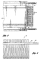
- the image processor digitizes a series of analog signals transmitted by the RGB camera and corresponding to each of the red, green and blue segments of the color image of the viewing area. These signals are converted by the image processor to three arrays 106, 108 and 110 (one for red, one for green and one for blue) of approximately 480 x 640 digital pixel values (from 0 to 255) for each of the red, green and blue images.
- the 480 x 640 pixel arrays are the digital representations of the red, green and blue portions of the color image of the approximately 36 inch by 27 inch viewing area 24.
- the system then normalizes each of the red, green and blue image arrays 106, 108 and 110 to correct the spectral imbalances in the light sources.
- this normalization is performed by modifying each of the pixel values in the red image array 106 by a normalizing value contained in a red image normalizing look-up table.
- the green image array 108 and blue image array 110 are likewise each normalized using green and blue image normalizing look-up tables respectively.
- the values in each of the red, green and blue image normalization look-up tables may be obtained through a calibration operation in which the operator views a neutral color background and digital values corresponding to the intensities of each of the red, green and blue domains are quantified, each, respectively, in the red, green and blue normalization look-up tables.
- the digital information acquired for the red, green and blue portions of each image may then be normalized prior to processing.
- One or more of these red, green and blue digital image arrays 112, 114 and 116 is then processed as described below for each acquired image to yield the selection information required to determine which of the scrap particles, if any, are to be separated from the others.
- the analog image signals generated by the CCD camera are digitized by the image processor (as described above) whenever the position sensor has determined that the conveyor belt has travelled the length of the viewing area.
- the conveyor is driven at speeds of up to 122 metres/minute 400 feet/minute), resulting in the acquisition of digital data corresponding to 2-3 images every second.
- the image processor 34 processes the above-described digital information as described below, and generates a series of discriminator signals which are transmitted to the separator controller 36.
- the separator controller 36 then selectively activates the air valves as a function of the discriminator signals to provide an ejecting force at the discharge end of the conveyor to eject the particles located in the selected cells of the imaginary matrix.
- the image processor 34 of the present invention analyzes the arrays of digital information, to develop another array 120 of discriminator signals indicating, for each pixel in each cell, whether that pixel satisfies a preselected criteria.
- the image processor examines the pixels to determine which of the pixels of the image is "red" enough to indicate the presence of copper or brass at that pixel location.
- the system subtracts the blue value from the red value for each of the corresponding pixels in the blue array 116 and red array 112, respectively, to determine whether the difference in those values is greater than a selected threshold, preferably 25.
- the value corresponding to that pixel in the resultant array 120 would be set to a non-zero value. If the difference in the corresponding pixels of the red and blue arrays of Figure 8 is less than 25, the corresponding pixel value in array 120 is set to zero.
- HSI hue, saturation, intensity
- a value is set to one for each position in the array corresponding to pixels which satisfy the threshold criteria and which are located in cell 1, 1 of the imaginary matrix. Similarly, for each such pixel in cell 1, 2 of the matrix, the corresponding value is set to 2.
- the system thereby creates an array 120 of values which indicate those pixels in each cell of the imaginary matrix of the viewing area for which the pixel at that location satisfies the preselected criteria.
- one embodiment of the present invention generates different non-zero values for each of the pixels in different cells of the resultant matrix 120 in order to allow for quick association of the non-zero pixels with a particular cell
- a simple binary scheme may also be employed (e.g., zero for all pixels not satisfying the color criteria and one for all pixels satisfying the color criteria) without departing from the spirit of the invention.
- the array 120 may then be further processed to determine a one bit discriminator value for each cell in the imaginary matrix. For example, for brass, copper/zinc separation in one embodiment, the number of pixels in cell 1,1 which satisfy the established criteria (i.e., are non-zero) are counted. If more than 50% of the pixels in that cell satisfy the criteria, a bit corresponding to cell 1,1 is set to one. This process is repeated for each of the cells in the array to yield an array 122 (shown in Figure 13) of values (0 or 1), one for each of the cells in the imaginary matrix, indicating which of the cells in that image has been selected (i.e., which of the cells contains colors corresponding to brass or copper particles).
- the analysis utilized to create array 120 may vary, and may employ any combination of the red, green and blue data of arrays 112, 114, and/or 116, respectively, depending on the color discrimination being attempted.
- both copper and brass can be easily distinguished from zinc based upon the relatively greater reflectance by copper and brass of the red portion of the spectrum from that of the zinc particles.
- a different, perhaps more complex, criteria may be utilized to separate copper particles from brass particles.
- the criteria should be selected so as to effectively separate the particles as desired, while minimizing the processing time associated with making the pixel-by-pixel, then cell-by-cell discrimination.
- the discriminator signal values for that image may be transmitted to the separator control 36 portion of the PLC.
- the discriminator signal values for an image will typically be a data block of m x n bits for an m x n matrix of cells. This data block is then written into a memory queue in the PLC.
- the logic in the separator control then transmits the discriminator signals from the queue on a row-by-row basis.
- the PLC determines, on the basis of information received from the position sensor 30, when the portion of the belt corresponding to a particular row of imaginary matrix cells has reached the discharge end of the conveyor.
- the PLC transmits the signals necessary to activate those air blast valves positioned across the width of the conveyor at locations corresponding to cells in the non-zero cells in the current row, thereby causing an ejecting force of air at each selected cell location for the current row.
- the PLC repeatedly processes the discriminator signals received from the image processor on a row-by-row basis, in this timed fashion, to effectively provide any ejecting force for each selected cell for each row in each of the endless series of images of the traveling conveyor belt.
- the system of the present invention provides several advantages over prior image processing sorting systems which allow for use of image processing in sorting scrap material.
- the system of the present invention analyzes the color information on a cell-by-cell basis, rather than particle-by-particle.
- processing time associated with identifying particles is eliminated. Processing speed is, therefore, not affected by the irregular shapes and sizes of the particles.
- the air nozzles of the separator are selectively activated on the basis of color discrimination for each cell in each row of the imaginary matrix of the viewing area to provide an ejecting force when the particles located on the conveyor belt in the positions corresponding to a particular row of cells in the imaginary matrix reaches the discharge end of the belt.
- the discriminator signals transmitted to the PLC will result in activation of the air nozzles at cell locations 129, 130 and 132.
- the PLC will activate the air nozzle(s) in the area of cells 136 and 138.
Landscapes
- Engineering & Computer Science (AREA)
- Multimedia (AREA)
- Physics & Mathematics (AREA)
- General Physics & Mathematics (AREA)
- Theoretical Computer Science (AREA)
- Sorting Of Articles (AREA)
- Combined Means For Separation Of Solids (AREA)
- Separation Of Solids By Using Liquids Or Pneumatic Power (AREA)
- Manufacture And Refinement Of Metals (AREA)
- Processing Of Solid Wastes (AREA)
Claims (21)
- Système pour trier des particules de déchets basé sur la couleur, comportant une bande transporteuse (22) pour acheminer les particules de déchets ; un capteur de position (30) pour déterminer la position des particules sur la bande transporteuse (22) ; un carénage d'éclairage (28) monté au-dessus de la bande transporteuse (22) pour fournir un éclairage constant, commandé, de différentes longueurs d'onde présélectionnées sur une zone de visualisation prédéfinie (24) le long de laquelle les particules sont acheminées par la bande transporteuse (22); un détecteur d'image (26) monté à l'intérieur du carénage au-dessus de la bande transporteuse (22) pour acquérir une image en couleur de la zone de visualisation (24) ; un processeur d'image (34) pour recevoir à partir du détecteur d'image (26) les données correspondant à une image de la zone de visualisation, et un séparateur (38) situé en aval du détecteur d'image (26) ; caractérisé en ce que :la bande transporteuse (22) a une surface fournissant un fond uniformément contrastant pour les particules ;le processeur d'image (34) comporte une logique pour diviser la zone de visualisation en une matrice de cellules indépendamment de la présence ou de l'absence de particules dans la zone de visualisation, dans lequel chaque cellule dans la matrice comporte une pluralité de pixels, chaque pixel ayant une valeur numérique correspondant à l'image acquise par le détecteur d'image, le processeur d'image comportant en outre un réseau résultant (120) d'emplacements mémoire correspondant au nombre total de pixels dans l'image, un réseau de signaux de discrimination (122) d'emplacements mémoire correspondant au réseau de cellules dans la matrice, et dans lequel la logique dans le processeur d'image comporte une logique pour déterminer pour chaque pixel si la valeur de ce pixel satisfait à un critère de couleur prédéterminé et établir une valeur dans l'emplacement dans le réseau résultant (120) correspondant à ce pixel en fonction de la détermination du critère de couleur, et déterminer pour chaque cellule si les valeurs dans le réseau résultant (120) correspondant aux pixels dans cette cellule satisfont à un critère de séparation prédéterminé et établir une valeur dans l'emplacement dans le réseau de signaux de discrimination (122) correspondant à la cellule en fonction de la détermination du critère de séparation, et émettre un signal de discrimination basé sur les valeurs dans le réseau de signaux de discrimination ;un premier contrôleur (32) pour recevoir un signal depuis le capteur de position (30), et pour envoyer un signal d'activation en vue d'acquérir une image à des intervalles cadencés basés sur le déplacement de la bande transporteuse ;et un deuxième contrôleur (36) pour recevoir des signaux de discrimination à partir du processeur d'image (34) et pour envoyer un signal de commande afin d'activer le séparateur (38) en fonction du signal de discrimination reçu depuis le processeur d'image (34) afin d'actionner sélectivement le séparateur (38) pour séparer des objets désirés des objets non désirés.
- Système selon la revendication 1, dans lequel la bande transporteuse (22) est une bande transporteuse à courroie sans fin opaque et comportant un dispositif de mouillage (41) monté en amont du détecteur d'image (26) pour mouiller la surface de la courroie de la bande transporteuse, créant ainsi un fond plus uniforme pour les objets supportés et acheminés sur celle-ci.
- Système selon la revendication 1 ou 2, dans lequel le carénage d'éclairage (28) s'ouvre vers le bas et comporte au moins une source de lumière (76) située au sein du carénage, un diffuseur pour diffuser la lumière de la source de lumière, et une source de puissance pour exciter de manière réglable la source de lumière afin de maintenir la source de lumière à un niveau d'éclairage prédéterminé, relativement constant.
- Système selon la revendication 1, 2 ou 3, dans lequel la bande transporteuse d'objets (22) comprend une pluralité de sections de bande transporteuse à courroie sans fin (88, 90, 92) situées sur la longueur de la bande et acheminant les particules à des vitesses croissantes d'une section de bande transporteuse à la suivante en amont du détecteur d'image (26), dans lequel chaque bande transporteuse suivante se déplace à une vitesse supérieure à la bande transporteuse précédente, augmentant ainsi la séparation des objets dans le sens d'acheminement au fur et à mesure que les objets sont transférés d'une bande transporteuse à la bande transporteuse adjacente, relativement plus rapide.
- Système selon la revendication 1, 2, 3 OU 4, dans lequel le séparateur (38) comprend une pluralité de jets d'air espacés (70) répartis sur la largeur de la bande transporteuse en aval du processeur d'image (34) en alignement respectif avec des colonnes de cellules de la matrice.
- Système selon l'une quelconque des revendications 1 à 5, dans lequel la bande transporteuse comprend un courroie sans fin opaque comportant une pluralité d'ouvertures de taille uniforme s'étendant linéairement le long de la courroie dans le sens d'acheminement, les ouvertures étant séparées par une distance uniforme, et le capteur de position comprend un oeil de cadencement comportant un émetteur de faisceau et un réflecteur, chacun monté en alignement avec l'autre avec la courroie entre eux de telle sorte qu'un signal soit émis vers le premier contrôleur et le deuxième contrôleur lors de l'émission du faisceau à travers les ouvertures dans la courroie au fur et à mesure que la courroie se déplace dans le sens d'acheminement.
- Système selon la revendication 3, dans lequel le système comporte en outre au moins un contrôleur de lumière connecté à la ou aux sources de lumière, et au moins un oeil photoélectrique connecté au ou aux contrôleurs de lumière et monté à l'intérieur du carénage pour détecter le niveau d'éclairage au sein du carénage et émettre périodiquement un signal vers le contrôleur de lumière correspondant au niveau d'éclairage détecté, par lequel les contrôleurs règlent automatiquement le niveau d'éclairage des lampes afin de maintenir l'éclairage sous le carénage à un niveau prédéterminé.
- Système selon la revendication 3, dans lequel le carénage (28) comporte un panneau supérieur opaque, des parois latérales opaques et une pluralité de sources de lumière montées à l'intérieur des parois latérales entourant l'ouverture dans le carénage au-dessus de la zone de visualisation, et une pluralité de panneaux diffuseurs montés à l'intérieur et de manière générale parallèlement aux parois latérales avec les sources de lumière positionnées entre les panneaux diffuseurs et les parois latérales opaques, éclairant ainsi la zone de visualisation avec une lumière égale, diffuse provenant de toutes les directions.
- Système selon la revendication 8, dans lequel le carénage (28) comporte un panneau supérieur opaque généralement carré (82) et quatre parois latérales opaques généralement rectangulaires, au moins une lampe montée à l'intérieur de chaque paroi latérale, quatre panneaux diffuseurs transparents généralement rectangulaires, chacun des panneaux diffuseurs étant monté de manière générale parallèlement à une paroi latérale correspondante avec une lampe entre eux, afin de fournir ainsi une lumière diffuse depuis les lampes sur la zone de visualisation.
- Système selon la revendication 8, dans lequel le carénage comporte en outre au moins un ventilateur monté à l'intérieur du carénage afin d'éliminer la chaleur, la poussière et les débris de la zone de visualisation.
- Système selon l'une quelconque des revendications 1 à 10, dans lequel le processeur d'image (34) comporte une logique pour transmettre au deuxième contrôleur un bloc de signaux de discrimination correspondant à une matrice complète de cellules couvrant une image et dans lequel le deuxième contrôleur comporte une logique pour transmettre indépendamment au séparateur les signaux de commande dans des blocs de données correspondant à un sous-ensemble de la matrice complète de cellules couvrant une image.
- Système selon la revendication 11, dans lequel le sous-ensemble est une rangée de la matrice de cellules.
- Système selon la revendication 1, dans lequel le critère de séparation comporte une détermination si le critère de couleur est satisfait par un nombre minimum présélectionné de pixels dans la cellule.
- Système selon la revendication 1, dans lequel le critères de séparation comporte une détermination si les pixels dans la cellule qui satisfont au critère de couleur satisfont à un critère de distribution présélectionné.
- Système selon la revendication 1, dans lequel le processeur d'image comporte en outre une logique pour établir la valeur dans le réseau résultant à une valeur non nulle pour chaque pixel satisfaisant au critère de couleur et à une valeur nulle pour chaque pixel ne satisfaisant pas au critère de couleur.
- Système selon la revendication 15, dans lequel le processeur d'image comporte en outre une logique pour associer une valeur unique à chacune des cellules, et où chacune des valeurs non nulles dans le réseau résultant est établie à la valeur unique de la cellule dans laquelle est situé le pixel associé.
- Système selon la revendication 2, dans lequel la source de lumière est une lampe fluorescente.
- Système selon la revendication 1, dans lequel le détecteur d'image est une caméra couleur à trois puces.
- Système selon la revendication 1, dans lequel le premier contrôleur et le deuxième contrôleur comprennent un contrôleur logique programmable unique qui est commodément programmé pour effectuer les deux fonctions de commande de cadencement associées, respectivement, en activant le détecteur d'image et désactivant le séparateur.
- Système selon la revendication 1, dans lequel le premier contrôleur comporte une logique pour déterminer si la bande transporteuse s'est déplacée d'une distance égale à la longueur de la zone de visualisation, et en fonction de cette détermination, envoyer un signal d'activation en vue d'acquérir une image, et dans lequel le deuxième contrôleur comporte une logique pour déterminer si la bande transporteuse s'est déplacée d'une distance égale à la longueur d'une cellule, et en fonction de cette détermination, envoyer un signal de commande pour activer le séparateur.
- Procédé mis en oeuvre par ordinateur pour trier des particules de déchets de forme aléatoire au fur et à mesure qu'elles sont acheminées dans des emplacements aléatoires sur une bande transporteuse mobile à travers une zone de visualisation prédéfinie, comportant les étapes de:acquisition de données correspondant à une image de la zone de visualisation ;division de la zone de visualisation en une matrice de cellules, chaque cellule comportant une pluralité de pixels, définissant un réseau résultant d'emplacements mémoire correspondant au nombre total de pixels dans l'image, chaque pixel ayant une valeur numérique correspondant à l'image acquise ;définition d'un réseau de signaux de discrimination d'emplacements mémoire correspondant au nombre total de cellules dans la matrice,détermination pour chaque pixel, indépendamment de la présence ou de l'absence de particules dans la zone de visualisation, si la valeur dans ce pixel satisfait à un critère de couleur prédéterminé et établissement d'une valeur dans l'emplacement dans le réseau résultant correspondant à ce pixel en fonction de la détermination du critère de couleur ;détermination pour chaque cellule si les valeurs dans le réseau résultant correspondant aux pixels dans cette cellule satisfont à un critère de séparation prédéterminé ;établissement d'une valeur dans l'emplacement du réseau de signaux de discrimination correspondant à la cellule en fonction de la détermination du critère de séparation ; etenvoi d'un signal de commande pour activer un séparateur situé en aval du détecteur d'image en fonction du signal de discrimination afin d'actionner sélectivement le séparateur pour séparer des particules désirées de particules non désirées.
Applications Claiming Priority (3)
| Application Number | Priority Date | Filing Date | Title |
|---|---|---|---|
| US176018 | 1993-12-30 | ||
| US08/176,018 US5520290A (en) | 1993-12-30 | 1993-12-30 | Scrap sorting system |
| PCT/US1994/014779 WO1995017974A1 (fr) | 1993-12-30 | 1994-12-23 | Systeme de tri de dechets metalliques |
Publications (3)
| Publication Number | Publication Date |
|---|---|
| EP0737112A1 EP0737112A1 (fr) | 1996-10-16 |
| EP0737112A4 EP0737112A4 (fr) | 1998-12-02 |
| EP0737112B1 true EP0737112B1 (fr) | 2002-04-10 |
Family
ID=22642642
Family Applications (1)
| Application Number | Title | Priority Date | Filing Date |
|---|---|---|---|
| EP95907243A Expired - Lifetime EP0737112B1 (fr) | 1993-12-30 | 1994-12-23 | Systeme de tri de dechets metalliques |
Country Status (9)
| Country | Link |
|---|---|
| US (2) | US5520290A (fr) |
| EP (1) | EP0737112B1 (fr) |
| AT (1) | ATE215852T1 (fr) |
| AU (1) | AU1553895A (fr) |
| CA (1) | CA2180005C (fr) |
| DE (1) | DE69430386T2 (fr) |
| DK (1) | DK0737112T3 (fr) |
| ES (1) | ES2177628T3 (fr) |
| WO (1) | WO1995017974A1 (fr) |
Cited By (1)
| Publication number | Priority date | Publication date | Assignee | Title |
|---|---|---|---|---|
| DE102010052338A1 (de) | 2010-11-25 | 2012-05-31 | Steinert Elektromagnetbau Gmbh | Verfahren und Einrichtung zur Einzelkornsortierung von Schüttgütern beliebiger Art |
Families Citing this family (70)
| Publication number | Priority date | Publication date | Assignee | Title |
|---|---|---|---|---|
| US5520290A (en) * | 1993-12-30 | 1996-05-28 | Huron Valley Steel Corporation | Scrap sorting system |
| US6060677A (en) * | 1994-08-19 | 2000-05-09 | Tiedemanns-Jon H. Andresen Ans | Determination of characteristics of material |
| US6545240B2 (en) | 1996-02-16 | 2003-04-08 | Huron Valley Steel Corporation | Metal scrap sorting system |
| US5911327A (en) * | 1996-10-02 | 1999-06-15 | Nippon Steel Corporation | Method of automatically discriminating and separating scraps containing copper from iron scraps |
| US5862919A (en) * | 1996-10-10 | 1999-01-26 | Src Vision, Inc. | High throughput sorting system |
| US6124560A (en) * | 1996-11-04 | 2000-09-26 | National Recovery Technologies, Inc. | Teleoperated robotic sorting system |
| US6100487A (en) * | 1997-02-24 | 2000-08-08 | Aluminum Company Of America | Chemical treatment of aluminum alloys to enable alloy separation |
| US5924575A (en) * | 1997-09-15 | 1999-07-20 | General Electric Company | Method and apparatus for color-based sorting of titanium fragments |
| US6266390B1 (en) * | 1998-09-21 | 2001-07-24 | Spectramet, Llc | High speed materials sorting using x-ray fluorescence |
| ES2276670T3 (es) * | 1999-03-19 | 2007-07-01 | Titech Visionsort As | Inspeccion de materiales. |
| US6369882B1 (en) | 1999-04-29 | 2002-04-09 | Advanced Sorting Technologies Llc | System and method for sensing white paper |
| US7019822B1 (en) * | 1999-04-29 | 2006-03-28 | Mss, Inc. | Multi-grade object sorting system and method |
| ATE291969T1 (de) * | 1999-04-30 | 2005-04-15 | Binder Co Ag | Verfahren und vorrichtung zum sortieren von altpapier |
| TW460336B (en) * | 1999-09-01 | 2001-10-21 | Japan Tobacco Inc | Foreign material removing device |
| TW461214B (en) * | 2000-02-18 | 2001-10-21 | Acer Peripherals Inc | Progressive image processing method of graphic image |
| US6765224B1 (en) * | 2000-12-29 | 2004-07-20 | Cognex Corporation | Machine vision method and system for the inspection of a material |
| ES2180447B1 (es) * | 2001-07-05 | 2004-04-16 | Fundacion Robotiker | Sistema y procedimiento para la separacion de particulas por medios opticos. |
| KR100496024B1 (ko) * | 2002-08-29 | 2005-06-16 | 대한민국 | 영상처리를 이용한 풋고추 선별기 |
| ATE443857T1 (de) * | 2002-11-01 | 2009-10-15 | Huron Valley Steel Corp | Abtastvorrichtung für verwendung in einer metallschrottsortiervorrichtung |
| NO317714B1 (no) * | 2002-11-08 | 2004-12-06 | Akvaforsk Inst For Akvakulturf | Belysningsboks |
| US7763820B1 (en) | 2003-01-27 | 2010-07-27 | Spectramet, Llc | Sorting pieces of material based on photonic emissions resulting from multiple sources of stimuli |
| US7893386B2 (en) * | 2003-11-14 | 2011-02-22 | Hewlett-Packard Development Company, L.P. | Laser micromachining and methods of same |
| US7099433B2 (en) * | 2004-03-01 | 2006-08-29 | Spectramet, Llc | Method and apparatus for sorting materials according to relative composition |
| US7564943B2 (en) * | 2004-03-01 | 2009-07-21 | Spectramet, Llc | Method and apparatus for sorting materials according to relative composition |
| DE202004012913U1 (de) * | 2004-08-12 | 2004-10-28 | Nobab Gmbh | Vorrichtung zum Erfassen und Bereitstellen von stückgutbezogenen Daten |
| US7326871B2 (en) * | 2004-08-18 | 2008-02-05 | Mss, Inc. | Sorting system using narrow-band electromagnetic radiation |
| WO2007112591A1 (fr) * | 2006-04-04 | 2007-10-11 | 6511660 Canada Inc. | Systeme et procede pour identifier et trier du materiel |
| DE102009007481A1 (de) * | 2009-01-30 | 2010-09-02 | Fraunhofer-Gesellschaft zur Förderung der angewandten Forschung e.V. | Fördersystem zum Transport von Materialien, insbesondere von Schüttgut |
| US8610019B2 (en) * | 2009-02-27 | 2013-12-17 | Mineral Separation Technologies Inc. | Methods for sorting materials |
| US8286800B2 (en) * | 2009-03-04 | 2012-10-16 | Panasonic Corporation | Separation method and separation apparatus |
| US8692148B1 (en) | 2010-07-19 | 2014-04-08 | National Recovery Technologies, Llc | Method and apparatus for improving performance in container sorting |
| US8841570B2 (en) * | 2010-10-13 | 2014-09-23 | Paramount Farms International Llc | System and method for aflatoxin detection |
| US8600545B2 (en) | 2010-12-22 | 2013-12-03 | Titanium Metals Corporation | System and method for inspecting and sorting particles and process for qualifying the same with seed particles |
| US8812149B2 (en) | 2011-02-24 | 2014-08-19 | Mss, Inc. | Sequential scanning of multiple wavelengths |
| MX2014001573A (es) * | 2011-08-10 | 2014-10-17 | ProASSORT GmbH | Clasificacion de chatarra. |
| US9114433B2 (en) | 2012-01-17 | 2015-08-25 | Mineral Separation Technologies, Inc. | Multi-fractional coal sorter and method of use thereof |
| GB201219184D0 (en) * | 2012-10-25 | 2012-12-12 | Buhler Sortex Ltd | Adaptive ejector valve array |
| US8809718B1 (en) | 2012-12-20 | 2014-08-19 | Mss, Inc. | Optical wire sorting |
| US9227229B2 (en) | 2013-04-08 | 2016-01-05 | National Recovery Technologies, Llc | Method to improve detection of thin walled polyethylene terephthalate containers for recycling including those containing liquids |
| US9234838B2 (en) | 2013-04-08 | 2016-01-12 | National Recovery Technologies, Llc | Method to improve detection of thin walled polyethylene terephthalate containers for recycling including those containing liquids |
| EP3281063B1 (fr) * | 2015-04-09 | 2023-11-15 | Compac Technologies Limited | Système de transport d'articles à éclairage diffus |
| US12403505B2 (en) | 2015-07-16 | 2025-09-02 | Sortera Technologies, Inc. | Sorting of aluminum alloys |
| US12109593B2 (en) | 2015-07-16 | 2024-10-08 | Sortera Technologies, Inc. | Classification and sorting with single-board computers |
| US10625304B2 (en) | 2017-04-26 | 2020-04-21 | UHV Technologies, Inc. | Recycling coins from scrap |
| US12280403B2 (en) | 2015-07-16 | 2025-04-22 | Sortera Technologies, Inc. | Sorting based on chemical composition |
| US10722922B2 (en) | 2015-07-16 | 2020-07-28 | UHV Technologies, Inc. | Sorting cast and wrought aluminum |
| US11964304B2 (en) | 2015-07-16 | 2024-04-23 | Sortera Technologies, Inc. | Sorting between metal alloys |
| US12508628B2 (en) | 2015-07-16 | 2025-12-30 | Sortera Technologies, Inc. | Sorting between metal alloys |
| US11969764B2 (en) | 2016-07-18 | 2024-04-30 | Sortera Technologies, Inc. | Sorting of plastics |
| US12290842B2 (en) | 2015-07-16 | 2025-05-06 | Sortera Technologies, Inc. | Sorting of dark colored and black plastics |
| US12208421B2 (en) | 2015-07-16 | 2025-01-28 | Sortera Technologies, Inc. | Metal separation in a scrap yard |
| US11278937B2 (en) | 2015-07-16 | 2022-03-22 | Sortera Alloys, Inc. | Multiple stage sorting |
| US12103045B2 (en) | 2015-07-16 | 2024-10-01 | Sortera Technologies, Inc. | Removing airbag modules from automotive scrap |
| US12246355B2 (en) | 2015-07-16 | 2025-03-11 | Sortera Technologies, Inc. | Sorting of Zorba |
| US12551931B2 (en) | 2015-07-16 | 2026-02-17 | Sortera Technologies, Inc. | Classifying of materials with contaminants |
| US12194506B2 (en) | 2015-07-16 | 2025-01-14 | Sortera Technologies, Inc. | Sorting of contaminants |
| US12017255B2 (en) | 2015-07-16 | 2024-06-25 | Sortera Technologies, Inc. | Sorting based on chemical composition |
| US10710119B2 (en) | 2016-07-18 | 2020-07-14 | UHV Technologies, Inc. | Material sorting using a vision system |
| US10207296B2 (en) | 2015-07-16 | 2019-02-19 | UHV Technologies, Inc. | Material sorting system |
| WO2017024035A1 (fr) | 2015-08-03 | 2017-02-09 | UHV Technologies, Inc. | Analyse de métaux pendant la fabrication de produits pharmaceutiques |
| CN105173655A (zh) * | 2015-09-24 | 2015-12-23 | 天津市华宇农药有限公司 | 一种瓶盖状态识别系统 |
| US9785851B1 (en) | 2016-06-30 | 2017-10-10 | Huron Valley Steel Corporation | Scrap sorting system |
| DE102016114465B4 (de) * | 2016-08-04 | 2022-12-01 | Hydro Aluminium Recycling Deutschland Gmbh | Vorrichtung und Verfahren zur Legierungsanalyse von Schrottfragmenten aus Metall |
| EP3600702B1 (fr) | 2017-03-28 | 2023-10-18 | Huron Valley Steel Corporation | Système et procédé de tri de déchets |
| US10898928B2 (en) | 2018-03-27 | 2021-01-26 | Huron Valley Steel Corporation | Vision and analog sensing scrap sorting system and method |
| DE102018210015B4 (de) * | 2018-06-20 | 2020-04-02 | Fraunhofer-Gesellschaft zur Förderung der angewandten Forschung e.V. | Vorrichtung und Verfahren zur Sortierung von pulverförmigem, partikelförmigem, granulatförmigem oder stückförmigem Material |
| WO2022185341A1 (fr) * | 2021-03-04 | 2022-09-09 | Ishitva Robotic Systems Pvt Ltd | Unité de tri pneumatique |
| KR20250073486A (ko) | 2022-10-21 | 2025-05-27 | 솔테라 테크노롤지스 인코포레이티드 | 재료 분류를 위한 보정 기법들 |
| US12303942B1 (en) | 2024-09-06 | 2025-05-20 | Trinity Metals, LLC | System and method for mixed material magnesium sorting |
| CN121266854A (zh) * | 2025-11-27 | 2026-01-06 | 中国地质大学(北京) | 一种基于图像识别技术的颗粒分析分选装置及方法 |
Family Cites Families (25)
| Publication number | Priority date | Publication date | Assignee | Title |
|---|---|---|---|---|
| US2717086A (en) * | 1954-07-14 | 1955-09-06 | Teleregister Corp | Control system for traveling conveyors |
| US3928183A (en) * | 1974-03-20 | 1975-12-23 | Emil S Asfour | Tobacco sorting apparatus |
| US3977526A (en) * | 1975-06-27 | 1976-08-31 | Sphere Investments Limited | Tracking systems for sorting apparatus |
| US4186836A (en) * | 1978-04-10 | 1980-02-05 | Ore-Ida Foods, Inc. | Differential reflectivity method and apparatus for sorting indiscriminately mixed items |
| DE3174515D1 (en) * | 1981-01-19 | 1986-06-05 | Gunsons Sortex Ltd | Sorting machine |
| US4493420A (en) * | 1981-01-29 | 1985-01-15 | Lockwood Graders (U.K.) Limited | Method and apparatus for detecting bounded regions of images, and method and apparatus for sorting articles and detecting flaws |
| JPS57187628A (en) * | 1981-05-14 | 1982-11-18 | Satake Eng Co Ltd | Photo-electric detector for color selecting machine |
| EP0089212B1 (fr) * | 1982-03-13 | 1987-10-28 | Kabushiki Kaisha Ishida Koki Seisakusho | Procédé et dispositif pour trier des articles |
| US4504888A (en) * | 1983-03-23 | 1985-03-12 | Pennywise Enterprises, Inc. | Photographer's diffuser light |
| GB2151018B (en) * | 1983-12-06 | 1987-07-22 | Gunsons Sortex Ltd | Sorting machine and method |
| US4687107A (en) * | 1985-05-02 | 1987-08-18 | Pennwalt Corporation | Apparatus for sizing and sorting articles |
| CA1242260A (fr) * | 1986-04-24 | 1988-09-20 | Leonard Kelly | Methode et dispositif de tri de rebuts metalliques divers |
| DE3614400C1 (de) * | 1986-04-25 | 1987-08-06 | Justus Technik Gmbh | Verfahren und Vorrichtung zum Steuern einer Farbsortiermaschine |
| US4745272A (en) * | 1986-09-15 | 1988-05-17 | Rca Licensing Corporation | Apparatus for identifying articles from received illumination with light adjustment means |
| DE3718672A1 (de) * | 1987-06-04 | 1988-12-15 | Metallgesellschaft Ag | Verfahren zur analyse von metallteilchen |
| ZA886696B (en) * | 1987-09-11 | 1989-04-26 | Alcan Int Ltd | Method of separating metal alloy particles |
| US5085325A (en) * | 1988-03-08 | 1992-02-04 | Simco/Ramic Corporation | Color sorting system and method |
| NL8803112A (nl) * | 1988-12-19 | 1990-07-16 | Elbicon Nv | Werkwijze en inrichting voor het sorteren van een stroom voorwerpen in afhankelijkheid van optische eigenschappen van de voorwerpen. |
| US5021645A (en) * | 1989-07-11 | 1991-06-04 | Eaton Corporation | Photoelectric color sensor for article sorting |
| JPH0781955B2 (ja) * | 1989-08-17 | 1995-09-06 | 東洋ガラス株式会社 | 透明体中の不透明異物除去方法 |
| WO1991004803A1 (fr) * | 1989-09-27 | 1991-04-18 | Colour Vision Systems Limited | Appareil a classer et a trier des objets |
| GB2256708A (en) * | 1991-06-11 | 1992-12-16 | Sumitomo Heavy Industries | Object sorter using neural network |
| ZA926325B (en) * | 1991-08-22 | 1993-03-11 | Tecnological Resources Pty Ltd | Ore sorting. |
| US5305894A (en) * | 1992-05-29 | 1994-04-26 | Simco/Ramic Corporation | Center shot sorting system and method |
| US5520290A (en) * | 1993-12-30 | 1996-05-28 | Huron Valley Steel Corporation | Scrap sorting system |
-
1993
- 1993-12-30 US US08/176,018 patent/US5520290A/en not_active Expired - Lifetime
-
1994
- 1994-12-23 WO PCT/US1994/014779 patent/WO1995017974A1/fr not_active Ceased
- 1994-12-23 CA CA002180005A patent/CA2180005C/fr not_active Expired - Lifetime
- 1994-12-23 AU AU15538/95A patent/AU1553895A/en not_active Abandoned
- 1994-12-23 DE DE69430386T patent/DE69430386T2/de not_active Expired - Lifetime
- 1994-12-23 DK DK95907243T patent/DK0737112T3/da active
- 1994-12-23 EP EP95907243A patent/EP0737112B1/fr not_active Expired - Lifetime
- 1994-12-23 AT AT95907243T patent/ATE215852T1/de active
- 1994-12-23 ES ES95907243T patent/ES2177628T3/es not_active Expired - Lifetime
-
1996
- 1996-10-24 US US08/736,275 patent/US5676256A/en not_active Expired - Lifetime
Cited By (2)
| Publication number | Priority date | Publication date | Assignee | Title |
|---|---|---|---|---|
| DE102010052338A1 (de) | 2010-11-25 | 2012-05-31 | Steinert Elektromagnetbau Gmbh | Verfahren und Einrichtung zur Einzelkornsortierung von Schüttgütern beliebiger Art |
| WO2012089185A1 (fr) | 2010-11-25 | 2012-07-05 | Steinert Elektromagnetbau Gmbh | Procédé et dispositif de tri granulométrique d'objets constitués de matières en vrac |
Also Published As
| Publication number | Publication date |
|---|---|
| ES2177628T3 (es) | 2002-12-16 |
| US5676256A (en) | 1997-10-14 |
| CA2180005A1 (fr) | 1995-07-06 |
| DK0737112T3 (da) | 2002-07-15 |
| DE69430386T2 (de) | 2002-12-12 |
| DE69430386D1 (de) | 2002-05-16 |
| US5520290A (en) | 1996-05-28 |
| ATE215852T1 (de) | 2002-04-15 |
| WO1995017974A1 (fr) | 1995-07-06 |
| EP0737112A4 (fr) | 1998-12-02 |
| AU1553895A (en) | 1995-07-17 |
| EP0737112A1 (fr) | 1996-10-16 |
| CA2180005C (fr) | 2004-07-13 |
Similar Documents
| Publication | Publication Date | Title |
|---|---|---|
| EP0737112B1 (fr) | Systeme de tri de dechets metalliques | |
| CA2268109C (fr) | Systeme de tri haute capacite | |
| EP0789633B1 (fr) | Appareil de tri | |
| US6078018A (en) | Sorting apparatus | |
| CA2971622C (fr) | Systeme de tri de rebuts | |
| US7351929B2 (en) | Method of and apparatus for high speed, high quality, contaminant removal and color sorting of glass cullet | |
| US5751833A (en) | Apparatus and method for inspecting articles such as agricultural produce | |
| EP0130715B1 (fr) | Machine de tri | |
| US7262380B1 (en) | Determination of characteristics of material | |
| JPH0321235B2 (fr) | ||
| KR20150119398A (ko) | 광학식 입상물 선별기 | |
| US5432545A (en) | Color detection and separation method | |
| US20140244027A1 (en) | Method and apparatus for sorting recycled material | |
| BR9405268A (pt) | Processo para a classificação ótica de produtos a granel | |
| US8436268B1 (en) | Method of and apparatus for type and color sorting of cullet | |
| EP0396290A2 (fr) | Méthode et appareil pour trier des matériaux discrets et des produits fabriqués | |
| US20260097419A1 (en) | Selector machine | |
| JPH0442611B2 (fr) |
Legal Events
| Date | Code | Title | Description |
|---|---|---|---|
| PUAI | Public reference made under article 153(3) epc to a published international application that has entered the european phase |
Free format text: ORIGINAL CODE: 0009012 |
|
| 17P | Request for examination filed |
Effective date: 19960725 |
|
| AK | Designated contracting states |
Kind code of ref document: A1 Designated state(s): AT BE CH DE DK ES FR GB GR IE IT LI LU MC NL PT SE |
|
| A4 | Supplementary search report drawn up and despatched |
Effective date: 19981019 |
|
| AK | Designated contracting states |
Kind code of ref document: A4 Designated state(s): AT BE CH DE DK ES FR GB GR IE IT LI LU MC NL PT SE |
|
| 17Q | First examination report despatched |
Effective date: 20000530 |
|
| GRAG | Despatch of communication of intention to grant |
Free format text: ORIGINAL CODE: EPIDOS AGRA |
|
| GRAG | Despatch of communication of intention to grant |
Free format text: ORIGINAL CODE: EPIDOS AGRA |
|
| GRAH | Despatch of communication of intention to grant a patent |
Free format text: ORIGINAL CODE: EPIDOS IGRA |
|
| GRAH | Despatch of communication of intention to grant a patent |
Free format text: ORIGINAL CODE: EPIDOS IGRA |
|
| REG | Reference to a national code |
Ref country code: GB Ref legal event code: IF02 |
|
| GRAA | (expected) grant |
Free format text: ORIGINAL CODE: 0009210 |
|
| AK | Designated contracting states |
Kind code of ref document: B1 Designated state(s): AT BE CH DE DK ES FR GB GR IE IT LI LU MC NL PT SE |
|
| PG25 | Lapsed in a contracting state [announced via postgrant information from national office to epo] |
Ref country code: GR Free format text: LAPSE BECAUSE OF FAILURE TO SUBMIT A TRANSLATION OF THE DESCRIPTION OR TO PAY THE FEE WITHIN THE PRESCRIBED TIME-LIMIT Effective date: 20020410 |
|
| REF | Corresponds to: |
Ref document number: 215852 Country of ref document: AT Date of ref document: 20020415 Kind code of ref document: T |
|
| REG | Reference to a national code |
Ref country code: CH Ref legal event code: EP |
|
| REG | Reference to a national code |
Ref country code: IE Ref legal event code: FG4D |
|
| REF | Corresponds to: |
Ref document number: 69430386 Country of ref document: DE Date of ref document: 20020516 |
|
| PG25 | Lapsed in a contracting state [announced via postgrant information from national office to epo] |
Ref country code: PT Free format text: LAPSE BECAUSE OF FAILURE TO SUBMIT A TRANSLATION OF THE DESCRIPTION OR TO PAY THE FEE WITHIN THE PRESCRIBED TIME-LIMIT Effective date: 20020710 |
|
| REG | Reference to a national code |
Ref country code: DK Ref legal event code: T3 |
|
| REG | Reference to a national code |
Ref country code: CH Ref legal event code: NV Representative=s name: ISLER & PEDRAZZINI AG |
|
| ET | Fr: translation filed | ||
| REG | Reference to a national code |
Ref country code: ES Ref legal event code: FG2A Ref document number: 2177628 Country of ref document: ES Kind code of ref document: T3 |
|
| PLBE | No opposition filed within time limit |
Free format text: ORIGINAL CODE: 0009261 |
|
| STAA | Information on the status of an ep patent application or granted ep patent |
Free format text: STATUS: NO OPPOSITION FILED WITHIN TIME LIMIT |
|
| 26N | No opposition filed |
Effective date: 20030113 |
|
| PG25 | Lapsed in a contracting state [announced via postgrant information from national office to epo] |
Ref country code: MC Free format text: LAPSE BECAUSE OF NON-PAYMENT OF DUE FEES Effective date: 20030701 |
|
| REG | Reference to a national code |
Ref country code: CH Ref legal event code: PCAR Free format text: ISLER & PEDRAZZINI AG;POSTFACH 1772;8027 ZUERICH (CH) |
|
| PGFP | Annual fee paid to national office [announced via postgrant information from national office to epo] |
Ref country code: DE Payment date: 20131230 Year of fee payment: 20 Ref country code: DK Payment date: 20131230 Year of fee payment: 20 Ref country code: GB Payment date: 20131227 Year of fee payment: 20 Ref country code: CH Payment date: 20131230 Year of fee payment: 20 Ref country code: AT Payment date: 20131204 Year of fee payment: 20 Ref country code: IE Payment date: 20131226 Year of fee payment: 20 Ref country code: SE Payment date: 20131230 Year of fee payment: 20 |
|
| PGFP | Annual fee paid to national office [announced via postgrant information from national office to epo] |
Ref country code: NL Payment date: 20131226 Year of fee payment: 20 Ref country code: LU Payment date: 20140106 Year of fee payment: 20 Ref country code: ES Payment date: 20131226 Year of fee payment: 20 Ref country code: FR Payment date: 20131217 Year of fee payment: 20 Ref country code: IT Payment date: 20131224 Year of fee payment: 20 |
|
| PGFP | Annual fee paid to national office [announced via postgrant information from national office to epo] |
Ref country code: BE Payment date: 20131227 Year of fee payment: 20 |
|
| REG | Reference to a national code |
Ref country code: DE Ref legal event code: R071 Ref document number: 69430386 Country of ref document: DE |
|
| REG | Reference to a national code |
Ref country code: DE Ref legal event code: R071 Ref document number: 69430386 Country of ref document: DE |
|
| REG | Reference to a national code |
Ref country code: NL Ref legal event code: V4 Effective date: 20141223 Ref country code: CH Ref legal event code: PL |
|
| REG | Reference to a national code |
Ref country code: DK Ref legal event code: EUP Effective date: 20141223 |
|
| REG | Reference to a national code |
Ref country code: GB Ref legal event code: PE20 Expiry date: 20141222 |
|
| REG | Reference to a national code |
Ref country code: IE Ref legal event code: MK9A |
|
| PG25 | Lapsed in a contracting state [announced via postgrant information from national office to epo] |
Ref country code: GB Free format text: LAPSE BECAUSE OF EXPIRATION OF PROTECTION Effective date: 20141222 |
|
| REG | Reference to a national code |
Ref country code: SE Ref legal event code: EUG |
|
| REG | Reference to a national code |
Ref country code: AT Ref legal event code: MK07 Ref document number: 215852 Country of ref document: AT Kind code of ref document: T Effective date: 20141223 |
|
| REG | Reference to a national code |
Ref country code: ES Ref legal event code: FD2A Effective date: 20150327 |
|
| PG25 | Lapsed in a contracting state [announced via postgrant information from national office to epo] |
Ref country code: IE Free format text: LAPSE BECAUSE OF EXPIRATION OF PROTECTION Effective date: 20141223 Ref country code: ES Free format text: LAPSE BECAUSE OF EXPIRATION OF PROTECTION Effective date: 20141224 |