EP0737465A2 - Hebevorrichtung für Behinderte - Google Patents
Hebevorrichtung für Behinderte Download PDFInfo
- Publication number
- EP0737465A2 EP0737465A2 EP96302545A EP96302545A EP0737465A2 EP 0737465 A2 EP0737465 A2 EP 0737465A2 EP 96302545 A EP96302545 A EP 96302545A EP 96302545 A EP96302545 A EP 96302545A EP 0737465 A2 EP0737465 A2 EP 0737465A2
- Authority
- EP
- European Patent Office
- Prior art keywords
- bed
- upright
- guide rail
- invalid
- movable
- Prior art date
- Legal status (The legal status is an assumption and is not a legal conclusion. Google has not performed a legal analysis and makes no representation as to the accuracy of the status listed.)
- Withdrawn
Links
- 238000005096 rolling process Methods 0.000 claims description 5
- 230000007246 mechanism Effects 0.000 abstract description 16
- 230000006835 compression Effects 0.000 description 6
- 238000007906 compression Methods 0.000 description 6
- 238000010586 diagram Methods 0.000 description 3
- 230000000474 nursing effect Effects 0.000 description 2
- 230000004044 response Effects 0.000 description 2
- 238000000034 method Methods 0.000 description 1
- 230000004048 modification Effects 0.000 description 1
- 238000012986 modification Methods 0.000 description 1
Images








Classifications
-
- B—PERFORMING OPERATIONS; TRANSPORTING
- B66—HOISTING; LIFTING; HAULING
- B66F—HOISTING, LIFTING, HAULING OR PUSHING, NOT OTHERWISE PROVIDED FOR, e.g. DEVICES WHICH APPLY A LIFTING OR PUSHING FORCE DIRECTLY TO THE SURFACE OF A LOAD
- B66F11/00—Lifting devices specially adapted for particular uses not otherwise provided for
-
- A—HUMAN NECESSITIES
- A61—MEDICAL OR VETERINARY SCIENCE; HYGIENE
- A61G—TRANSPORT, PERSONAL CONVEYANCES, OR ACCOMMODATION SPECIALLY ADAPTED FOR PATIENTS OR DISABLED PERSONS; OPERATING TABLES OR CHAIRS; CHAIRS FOR DENTISTRY; FUNERAL DEVICES
- A61G7/00—Beds specially adapted for nursing; Devices for lifting patients or disabled persons
- A61G7/10—Devices for lifting patients or disabled persons, e.g. special adaptations of hoists thereto
- A61G7/1013—Lifting of patients by
- A61G7/1015—Cables, chains or cords
-
- A—HUMAN NECESSITIES
- A61—MEDICAL OR VETERINARY SCIENCE; HYGIENE
- A61G—TRANSPORT, PERSONAL CONVEYANCES, OR ACCOMMODATION SPECIALLY ADAPTED FOR PATIENTS OR DISABLED PERSONS; OPERATING TABLES OR CHAIRS; CHAIRS FOR DENTISTRY; FUNERAL DEVICES
- A61G7/00—Beds specially adapted for nursing; Devices for lifting patients or disabled persons
- A61G7/002—Beds specially adapted for nursing; Devices for lifting patients or disabled persons having adjustable mattress frame
- A61G7/012—Beds specially adapted for nursing; Devices for lifting patients or disabled persons having adjustable mattress frame raising or lowering of the whole mattress frame
-
- A—HUMAN NECESSITIES
- A61—MEDICAL OR VETERINARY SCIENCE; HYGIENE
- A61G—TRANSPORT, PERSONAL CONVEYANCES, OR ACCOMMODATION SPECIALLY ADAPTED FOR PATIENTS OR DISABLED PERSONS; OPERATING TABLES OR CHAIRS; CHAIRS FOR DENTISTRY; FUNERAL DEVICES
- A61G7/00—Beds specially adapted for nursing; Devices for lifting patients or disabled persons
- A61G7/10—Devices for lifting patients or disabled persons, e.g. special adaptations of hoists thereto
- A61G7/1013—Lifting of patients by
- A61G7/1017—Pivoting arms, e.g. crane type mechanisms
-
- A—HUMAN NECESSITIES
- A61—MEDICAL OR VETERINARY SCIENCE; HYGIENE
- A61G—TRANSPORT, PERSONAL CONVEYANCES, OR ACCOMMODATION SPECIALLY ADAPTED FOR PATIENTS OR DISABLED PERSONS; OPERATING TABLES OR CHAIRS; CHAIRS FOR DENTISTRY; FUNERAL DEVICES
- A61G7/00—Beds specially adapted for nursing; Devices for lifting patients or disabled persons
- A61G7/10—Devices for lifting patients or disabled persons, e.g. special adaptations of hoists thereto
- A61G7/1025—Lateral movement of patients, e.g. horizontal transfer
- A61G7/1034—Rollers, rails or other means
-
- A—HUMAN NECESSITIES
- A61—MEDICAL OR VETERINARY SCIENCE; HYGIENE
- A61G—TRANSPORT, PERSONAL CONVEYANCES, OR ACCOMMODATION SPECIALLY ADAPTED FOR PATIENTS OR DISABLED PERSONS; OPERATING TABLES OR CHAIRS; CHAIRS FOR DENTISTRY; FUNERAL DEVICES
- A61G7/00—Beds specially adapted for nursing; Devices for lifting patients or disabled persons
- A61G7/10—Devices for lifting patients or disabled persons, e.g. special adaptations of hoists thereto
- A61G7/104—Devices carried or supported by
- A61G7/1044—Stationary fixed means, e.g. fixed to a surface or bed
-
- A—HUMAN NECESSITIES
- A61—MEDICAL OR VETERINARY SCIENCE; HYGIENE
- A61G—TRANSPORT, PERSONAL CONVEYANCES, OR ACCOMMODATION SPECIALLY ADAPTED FOR PATIENTS OR DISABLED PERSONS; OPERATING TABLES OR CHAIRS; CHAIRS FOR DENTISTRY; FUNERAL DEVICES
- A61G7/00—Beds specially adapted for nursing; Devices for lifting patients or disabled persons
- A61G7/10—Devices for lifting patients or disabled persons, e.g. special adaptations of hoists thereto
- A61G7/1073—Parts, details or accessories
- A61G7/1076—Means for rotating around a vertical axis
-
- A—HUMAN NECESSITIES
- A61—MEDICAL OR VETERINARY SCIENCE; HYGIENE
- A61G—TRANSPORT, PERSONAL CONVEYANCES, OR ACCOMMODATION SPECIALLY ADAPTED FOR PATIENTS OR DISABLED PERSONS; OPERATING TABLES OR CHAIRS; CHAIRS FOR DENTISTRY; FUNERAL DEVICES
- A61G7/00—Beds specially adapted for nursing; Devices for lifting patients or disabled persons
- A61G7/10—Devices for lifting patients or disabled persons, e.g. special adaptations of hoists thereto
- A61G7/1049—Attachment, suspending or supporting means for patients
- A61G7/1061—Yokes
Definitions
- the present invention relates to a lift apparatus for an invalid, which is employed for lifting an invalid such as a sick person, a physically handicapped person or a bed-ridden old person for nursing him.
- Japanese Patent Laying-Open No. 2-215462 (1990) proposes an improved bed apparatus.
- this bed apparatus is rendered employable in a six- or four-and-a half-mat room, with provision of a lift apparatus which can lift up or lay down an invalid from or on the bed body, or move him to a bedside.
- the pair of uprights are movable between positions within and out of the cross-directional dimension of the bed apparatus.
- the side bars are vertically movable along the uprights and stoppable on the moved positions wherever the uprights are located. Consequently, the side bars can be located in arbitrary positions in the range of spaces above and beside the bed body.
- the side bars When the side bars are employed for supporting the body of an invalid, therefore, the invalid who lies on the bed body can be lifted up from the bed body or moved to a bedside, and vice versa.
- the bed sheet can be promptly exchanged, or the invalid can be readily bathed or seated on a wheelchair or a chamber pot.
- An object of the present invention is to provide a lift apparatus for an invalid, which can be assembled independently of a bed and can be mounted on a vertically movable bed.
- the inventive lift apparatus for an invalid comprises a guide rail which is detachably mounted on a bed on one longitudinal end thereof to extend widthwise along the bed, a movable body which is guided to be movable along the guide rail, and lift means which is mounted on the movable body.
- the lift means includes an upright which is fixed to the movable body on a side portion to extend in the vertical direction, and an arm member having a first end which is coupled to an upper end portion of the upright and a second end serving as a working end.
- the aforementioned guide rail is mounted on a vertically movable part of a bed, and the movable body is vertically slidably mounted on the upright.
- the lift apparatus for an invalid may comprise no elements, such as the side bars included in the lift apparatus which is assembled with the aforementioned conventional bed apparatus, having lengths corresponding to the longitudinal dimension of the bed.
- the lift apparatus for an invalid itself is miniaturized, and can be readily handled.
- the guide rail can be mounted through a relatively heavy bed, whereby the same can be brought into a strongly fixed state with no requirement for a specific member for mounting the guide rail.
- the number of components which are required for the lift apparatus for an invalid can be reduced.
- the upright of the lift means itself is not vertically moved but enables cross-directional movement along the guide rail upon vertical movement of the movable part of the bed comprising the vertically movable mechanism.
- the apparatus further comprises another guide rail mounted on a fixed part of the bed vertically movably supporting the movable part and another movable body guided to be movable along the fixed guide rail.
- the lift means is supported not only by the guide rail but by the floor face through the wheel which is provided on the lower end portion of the upright of the lift means, whereby stability is further improved.
- the arm member is driven by the actuator to be rotated about the upper end portion of the lift means, whereby the height of the forward end of the arm member can be freely changed.
- This arm member is mounted to be also rotatable about the axis of the upright.
- the working end of the arm member can be made to extend to a position sufficiently separated from a side portion of the bed by rotating the arm member about the axis of the upright with no extension of the upright itself beyond the cross-directional range of the bed. Consequently, the lift apparatus can softly move the invalid over a wide range, in order to nurse him.
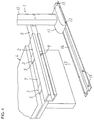
- the lift apparatus 1 comprises a guide rail 2.
- the guide rail 2, which has a C-shaped section, for example, is detachably mounted on a bed 4 by clamp devices 3, to extend widthwise along the bed 4 on one longitudinal end portion thereof.
- the clamp devices 3 comprise clamp fittings 5 having U-shaped sections which are fixed to the guide rail 2, and manually rotatable tie bolts 6 which are fitted with the clamp fittings 5.
- a projection 7 is formed on the longitudinal end portion of the bed 4, so that the clamp devices 3 clamp this projection 7, thereby mounting the guide rail 2 on the bed 4.
- the movable body 8 is mounted on a side portion of a vertically extending upright 10. As understood from a state shown by phantom lines in Fig. 2, the upright 10 is preferably mounted on one longitudinal end of the movable body 8.
- a base 11 is provided on a lower end portion of the upright 10, for rotatably holding a plurality of wheels 12. Rolling of these wheels 12 is preferably guided by a wheel guide rail 14 which is fixed onto a floor face 13.
- the wheel guide rail 14 is fixed to the floor face 13 by screws 15, for example. Head portions of these screws 15 may project from the upper surface of the wheel guide rail 14, thereby serving as stoppers defining the range of rolling of the wheels 12.
- a beam 16 is formed to extend from an upper end portion of the upright 10 toward the longitudinal center of the bed 4.
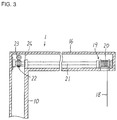
- the upright 10 and the beam 16 preferably have hollow structures, as shown in Fig. 3.
- a hanger member 17 is arranged under a forward end portion of the beam 16, to be vertically movable. According to this embodiment, the hanger member 17 is suspended from the forward end portion of the beam 16 through a wire 18.
- a hoist gear 19 for hoisting the wire 18 is provided in relation to the beam 16.
- the hoist gear 19 comprises a drum 20 for taking up the wire 18.
- the drum 20 is fixed to a first end of a rotatably supported shaft 21, and a worm wheel 22 is fixed to a second end of this shaft 21.
- a worm 23 is arranged to engage with the worm wheel 22, and rotated by a motor 24 which is mounted on an outer part of the upright 10.
- the motor 24, which is reciprocally rotatable, rotates the drum 20 in a desired direction, thereby vertically moving the hanger member 17.
- the invalid In order to lift an invalid who lies on the bed 4, the invalid is hammocked, for example, and the hanger member 17 is downwardly moved and coupled with the hammock. Then, the hanger member 17 is upwardly moved, for suspending the invalid along with the hammock. In this state, a sheet which is spread on the bed 4 can be readily exchanged, for example.
- the invalid can be bathed or seated on a wheelchair or a chamber pot, by downwardly moving the hanger member 17.
- the aforementioned operation may be reversely performed.
- hanger member 17 which is suitably shaped for suspending a hammock is employed in the aforementioned embodiment, a hanger member having another shape may alternatively be employed.
- the structure for detachably mounting the guide rail 2 on the bed 4 can be arbitrarily modified in response to the structure provided on the bed 4.
- One of such modifications is now described with reference to Fig. 5.
- Fig. 5 is adapted to illustrate a lift apparatus la for an invalid according to a second embodiment of the present invention.
- elements corresponding to those shown in Fig. 1 are denoted by similar reference numerals, to omit redundant description.
- a bed 4a comprises a head guard 25 including a vertical pair of rods 26 and 27 which extend widthwise.
- a guide rail 2 is detachably mounted on the bed 4a by clamp devices 28 which are selectively fixed to these rods 26 and 27.
- the clamp devices 28 comprise J-shaped first clamp fittings 29 which are fixed to the guide rail 2, so that manually rotatable first tie bolts 30 are fitted with the first clamp fittings 29. Parts of the first clamp fittings 29 and the first tie bolts 30 clamp the upper rod 26, thereby fixing the first clamp fittings 29 to the rod 26.
- the clamp devices 28 further comprise J-shaped second clamp fittings 32 which are detachably mounted on the first clamp fittings 29 by screws 31, so that manually rotatable second tie bolts 33 are fitted with the second clamp fittings 32. Parts of the second clamp fittings 32 and the second tie bolts 33 clamp the lower rod 27, thereby fixing the second clamp fittings 32 to the rod 27. Thus, the guide rail 2 is fixed to the bed 4a through the clamp devices 28.
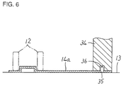
- a part of the wheel guide rail 14a is laid under the leg portion 34 to be fixed to a floor face 13, so that the wheel guide rail 14a is fixed through the weight of the bed which is applied to the floor face 13.
- upwardly projecting pins 35 are provided on the wheel guide rail 14a, while cavities 36 for receiving the pins 35 are provided on the lower surface of the leg portion 34.
- wheel guide rail 14 or 14a is employed in each of the aforementioned embodiments, the wheels 12 may alternatively directly roll on the floor face 13 with no employment of such a wheel guide rail.
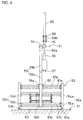
- a lift apparatus 51 for an invalid is mounted on one longitudinal end of a bed 52 comprising a vertical driving mechanism in this embodiment.
- a first longitudinal end of a body 53 of the bed 52 is supported by a pair of bed uprights 56a and 56b on both cross-directional ends thereof.
- a first end of the body 53 of the bed 52 is fixed to movable bed upright parts 54a and 54b forming the bed uprights 56a and 56b, so that the body 53 of the bed 52 is vertically driven following vertically movement of the movable bed upright parts 54a and 54b by the vertical driving mechanism as described later.
- the bed uprights 56a and 56b comprise the aforementioned movable bed upright parts 54a and 54b and fixed bed upright parts 55a and 55b vertically movably supporting these movable bed upright parts 54a and 54b respectively.
- a first guide rail 57a is mounted on the pair of movable bed upright parts 54a and 54b to link portions which are close to upper ends thereof with each other, while a second guide rail 57b is mounted to link the pair of fixed bed upright parts 55a and 55b with each other.
- the first and second guide rails 57a and 57b are fastened/fixed to the bed uprights 56a and 56b by bolting or the like, to be readily attached to and detached from the same.
- the first and second guide rails 57a and 57b are provided with first and second movable members 58a and 58b which are moved along the same respectively.
- the first and second movable members 58a and 58b are mounted on side portions of an upright 59 of the lift apparatus 51, for vertically supporting this upright 59. While the second movable member 58b is fixed to a portion which is close to the lower end of the upright 59, the first movable member 58a is mounted on the upright 59 through a hollow cylindrical sleeve 60 slidably receiving the upright 59, so that the movable bed upright parts 54a and 54b of the bed uprights 56a and 56b can be vertically moved while fixing the upright 59 in the vertical direction by this mechanism.
- Fig. 20 is a plan view showing the lift apparatus 51 which is most approached to a side of the bed 52.
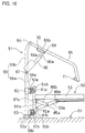
- a base 63 which is provided with a pair of wheels 62a and 62b for rolling along a floor face 61 on both cross-directional ends of the bed 52 is fixed to the lower end of the upright 59 of the lift apparatus 51. Due to this mechanism, the upright 59 of the lift apparatus 51 is also supported by the floor face 61 in addition to the first and second guide rails 57a and 57b, to be stably moved widthwise along the bed 52.
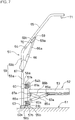
- the upright 59 of the lift apparatus 51 includes a lower upright 59a which is mounted on the first and second movable members 58a and 58b, and an upper upright 59b which is mounted on the upper end of the lower upright bar 59a to be rotatable about its central axis.
- An arm member 65 is mounted on the upper end of the upper upright 59b so that a first end thereof is rotatable about a rotation fulcrum 64.
- An actuator 66 has a base end portion which is rotatably supported by a pin 67 in the vicinity of the lower end of the upper upright 59b, and a working end which is rotatably supported by a pin 68 on a first end of an auxiliary link 69a on the forward end of a driving rod 66a.
- a second end of the auxiliary link 69a is connected to a bracket 69b, which is fixed to the arm member 65, to be rotatable about a pin 70.
- a shackle 71 for suspending a hanger member or the like is provided on a lower part of a portion close to the forward end of the arm member 65.
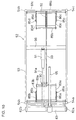
- a cross beam 81a is provided to link the movable bed upright parts 54a and 54b with each other on the positions provided with the first guide rail 57a, while another cross beam 81b is provided to link the fixed bed upright parts 55a and 55b with each other on the positions provided with the second guide rail 57b.
- cross beams 81c and 81d are mounted to link movable bed upright parts 54c and 54d and fixed bed upright parts 55c and 55d with each other in correspondence to the cross beams 81a and 81b respectively.
- a shaft 89a is mounted to portions which are close to the upper ends of the pair of lower link members 83a and 83b respectively, to link the same with each other.
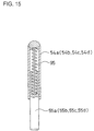
- a pair of lower link auxiliary members 95a and 95b are provided on positions of the shafts 84a and 89a which are slightly closer to the lower link member 83b to link the same with each other, and integrally rotated with the lower link members 83a and 83b.
- the forward end of a driving rod 91a of an actuator 91 is rotatably connected to portions which are close to the upper ends of the pair of lower link auxiliary members 95a and 95b by a pin 90.
- a pair of brackets 82c and 82d are fixed to the cross beam 81d on positions which are symmetrical to those on the first end, so that a pair of lower link members 83c and 83d are rotatably connected thereto by a shaft 84b.
- Upper link members 86c and 86d are rotatably supported in positions which are close to the longitudinal centers of the lower link members 83c and 83d through a pin 85b, so that second ends thereof are rotatably supported by a shaft 88b which is mounted on a bracket 87c respectively.
- a shaft 89b is provided in the vicinity of the upper ends of the lower link members 83c and 83d, to link the same with each other.
- a chain 92 has a first end which is fixed to a substantially central portion of the shaft 89b and a second end which is connected to a wire 93.
- a first end of the wire 93 which is opposite to the chain 92 is mounted on a portion close to the center of the shaft 89a.
- a cross beam 96 is fixed to a portion which is close to the longitudinal center of the bed body 53, to extend widthwise along the bed 52.
- the pair of lower link members 83a and 83b are rotated about the shaft 84a due to a driving operation of the actuator 91 in a bed driving mechanism of this embodiment.
- the upper link members 86a and 86b are upwardly pressed, whereby the shaft 88a and the movable bed upright parts 54a and 54b which are integrally fixed thereto are upwardly moved.
- Fig. 12 shows a portion around the first end of the bed body 53 which is upwardly moved by the driving operation of the actuator 91, i.e., a portion around the lift apparatus 51.
- the driving rod 91a of the actuator 91 is moved toward the interior of the actuator 91.
- the pair of lower link members 83a and 83b are rotated/driven in a direction opposite to that for upwardly moving the bed 52, whereby the shaft 88a and the movable bed upright parts 54a and 54b are downwardly moved through the pair of upper link members 86a and 86b.
- the second guide rail 57b is mounted on the side of the movable bed upright part 54b, whereby a second movable member 58b is mounted on a lower upright 59a to be vertically slidable through a sleeve 160.
- Fig. 19 illustrates the bed 52 in the same state as that shown in Fig. 18, as viewed from its first end.
- the lift apparatuses 51 can be further stably and reliably moved by providing the wheel guide rails 57a and 57b for guiding the wheels 62a and 62b as shown in the lift apparatuses 1 and 1a according to the first to third embodiments.
- the lift apparatuses having integrated uprights and arm members shown in the first to third embodiments can also be mounted on the beds 52 having the vertical moving mechanisms shown in the fourth and fifth embodiments,.as a matter of course.
Landscapes
- Health & Medical Sciences (AREA)
- Life Sciences & Earth Sciences (AREA)
- Nursing (AREA)
- Animal Behavior & Ethology (AREA)
- General Health & Medical Sciences (AREA)
- Public Health (AREA)
- Veterinary Medicine (AREA)
- Engineering & Computer Science (AREA)
- Geology (AREA)
- Mechanical Engineering (AREA)
- Structural Engineering (AREA)
- Invalid Beds And Related Equipment (AREA)
Applications Claiming Priority (2)
| Application Number | Priority Date | Filing Date | Title |
|---|---|---|---|
| JP08529595A JP3340277B2 (ja) | 1994-04-11 | 1995-04-11 | 病弱者リフト装置 |
| JP85295/95 | 1995-04-11 |
Publications (2)
| Publication Number | Publication Date |
|---|---|
| EP0737465A2 true EP0737465A2 (de) | 1996-10-16 |
| EP0737465A3 EP0737465A3 (de) | 1997-03-05 |
Family
ID=13854600
Family Applications (1)
| Application Number | Title | Priority Date | Filing Date |
|---|---|---|---|
| EP96302545A Withdrawn EP0737465A3 (de) | 1995-04-11 | 1996-04-11 | Hebevorrichtung für Behinderte |
Country Status (3)
| Country | Link |
|---|---|
| EP (1) | EP0737465A3 (de) |
| KR (1) | KR960037559A (de) |
| CN (1) | CN1135877A (de) |
Cited By (4)
| Publication number | Priority date | Publication date | Assignee | Title |
|---|---|---|---|---|
| DE102013002373A1 (de) * | 2013-02-09 | 2014-08-14 | Josef Klimm | Krankenbett mit Hebevorrichtung |
| CN109106517A (zh) * | 2018-09-28 | 2019-01-01 | 上海联影医疗科技有限公司 | 一种转移床 |
| CN111888106A (zh) * | 2020-08-21 | 2020-11-06 | 耿凡龙 | 心内科患者急救转运担架床 |
| US12447080B2 (en) | 2019-11-21 | 2025-10-21 | Liko Research & Development Ab | Lifting devices positionable in high range positions and low range positions |
Families Citing this family (4)
| Publication number | Priority date | Publication date | Assignee | Title |
|---|---|---|---|---|
| CN107595508B (zh) * | 2017-09-19 | 2020-04-28 | 董景云 | 一种医疗护理床 |
| CN109431717B (zh) * | 2018-11-08 | 2020-07-17 | 王栋 | 一种多功能医院病人换床支架 |
| CN111281707A (zh) * | 2020-03-22 | 2020-06-16 | 袁雷 | 一种医院移动病人的设备 |
| CN119139100B (zh) * | 2024-11-19 | 2025-01-28 | 中国人民解放军总医院第五医学中心 | 一种神经内科检查托举装置 |
Family Cites Families (2)
| Publication number | Priority date | Publication date | Assignee | Title |
|---|---|---|---|---|
| US4686727A (en) * | 1985-06-03 | 1987-08-18 | Lawrence H. Wilkinson | Convenience bar assembly for hospital bed |
| JP2868873B2 (ja) * | 1990-09-14 | 1999-03-10 | アップリカ葛西株式会社 | ベッド装置 |
-
1996
- 1996-04-08 CN CN96101947A patent/CN1135877A/zh active Pending
- 1996-04-09 KR KR1019960011336A patent/KR960037559A/ko not_active Abandoned
- 1996-04-11 EP EP96302545A patent/EP0737465A3/de not_active Withdrawn
Cited By (5)
| Publication number | Priority date | Publication date | Assignee | Title |
|---|---|---|---|---|
| DE102013002373A1 (de) * | 2013-02-09 | 2014-08-14 | Josef Klimm | Krankenbett mit Hebevorrichtung |
| CN109106517A (zh) * | 2018-09-28 | 2019-01-01 | 上海联影医疗科技有限公司 | 一种转移床 |
| CN109106517B (zh) * | 2018-09-28 | 2024-03-12 | 上海联影医疗科技股份有限公司 | 一种转移床 |
| US12447080B2 (en) | 2019-11-21 | 2025-10-21 | Liko Research & Development Ab | Lifting devices positionable in high range positions and low range positions |
| CN111888106A (zh) * | 2020-08-21 | 2020-11-06 | 耿凡龙 | 心内科患者急救转运担架床 |
Also Published As
| Publication number | Publication date |
|---|---|
| CN1135877A (zh) | 1996-11-20 |
| EP0737465A3 (de) | 1997-03-05 |
| KR960037559A (ko) | 1996-11-19 |
Similar Documents
| Publication | Publication Date | Title |
|---|---|---|
| EP1263385B1 (de) | Bettseitenteil | |
| CN1034712C (zh) | 具有单个调节器的可调节床 | |
| US3958283A (en) | Elevating and Trendelenburg mechanism for an adjustable bed | |
| EP0736275B1 (de) | Ein verbessertes in die Höhe verstellbares Bettgestell | |
| US5636394A (en) | Hospital bed with rack and pinion stabilizer | |
| JP2987290B2 (ja) | ベッド装置 | |
| US4860394A (en) | Hospital bed or hospital table | |
| US5105486A (en) | Adjustable bed | |
| EP0737465A2 (de) | Hebevorrichtung für Behinderte | |
| CN114795725B (zh) | 一种护理床翻身机构及电动翻身护理床 | |
| EP0221037A2 (de) | Mechanismus zum Heben und Niederlassen von Arbeitstischen aller Art | |
| US3300793A (en) | Hospital and like beds | |
| JPH02200262A (ja) | 仰臥台に於ける床部支持フレームの昇降機構及びその昇降機構を備えた仰臥台 | |
| US5173975A (en) | Adjustable bed with side rail | |
| JP3340277B2 (ja) | 病弱者リフト装置 | |
| EP0756858A1 (de) | Krankenhebevorrichtung | |
| WO1998020829A1 (en) | A suspension system, and a height-adjustable bed incorporating the suspension system | |
| JPH0919462A (ja) | 介護用ベッド | |
| JPH0426856B2 (de) | ||
| CN217448316U (zh) | 一种移位机 | |
| JPH0650479Y2 (ja) | テーブルリフター | |
| JP3989481B2 (ja) | 可動ベッド | |
| JP3458783B2 (ja) | リフタ装置 | |
| JP4679742B2 (ja) | 昇降訓練装置 | |
| JPH08280755A (ja) | 昇降式ベッド用リフト装置 |
Legal Events
| Date | Code | Title | Description |
|---|---|---|---|
| PUAI | Public reference made under article 153(3) epc to a published international application that has entered the european phase |
Free format text: ORIGINAL CODE: 0009012 |
|
| AK | Designated contracting states |
Kind code of ref document: A2 Designated state(s): DE ES FR GB IT |
|
| PUAL | Search report despatched |
Free format text: ORIGINAL CODE: 0009013 |
|
| AK | Designated contracting states |
Kind code of ref document: A3 Designated state(s): DE ES FR GB IT |
|
| 17P | Request for examination filed |
Effective date: 19970326 |
|
| STAA | Information on the status of an ep patent application or granted ep patent |
Free format text: STATUS: THE APPLICATION HAS BEEN WITHDRAWN |
|
| 18W | Application withdrawn |
Withdrawal date: 19970827 |