EP0737543A2 - Installation d'usinage et/ou de montage - Google Patents
Installation d'usinage et/ou de montage Download PDFInfo
- Publication number
- EP0737543A2 EP0737543A2 EP96105340A EP96105340A EP0737543A2 EP 0737543 A2 EP0737543 A2 EP 0737543A2 EP 96105340 A EP96105340 A EP 96105340A EP 96105340 A EP96105340 A EP 96105340A EP 0737543 A2 EP0737543 A2 EP 0737543A2
- Authority
- EP
- European Patent Office
- Prior art keywords
- satellite
- conveyor
- main conveyor
- processing
- conveyors
- Prior art date
- Legal status (The legal status is an assumption and is not a legal conclusion. Google has not performed a legal analysis and makes no representation as to the accuracy of the status listed.)
- Granted
Links
Images
Classifications
-
- B—PERFORMING OPERATIONS; TRANSPORTING
- B65—CONVEYING; PACKING; STORING; HANDLING THIN OR FILAMENTARY MATERIAL
- B65G—TRANSPORT OR STORAGE DEVICES, e.g. CONVEYORS FOR LOADING OR TIPPING, SHOP CONVEYOR SYSTEMS OR PNEUMATIC TUBE CONVEYORS
- B65G37/00—Combinations of mechanical conveyors of the same kind, or of different kinds, of interest apart from their application in particular machines or use in particular manufacturing processes
- B65G37/02—Flow-sheets for conveyor combinations in warehouses, magazines or workshops
-
- B—PERFORMING OPERATIONS; TRANSPORTING
- B23—MACHINE TOOLS; METAL-WORKING NOT OTHERWISE PROVIDED FOR
- B23P—METAL-WORKING NOT OTHERWISE PROVIDED FOR; COMBINED OPERATIONS; UNIVERSAL MACHINE TOOLS
- B23P21/00—Machines for assembling a multiplicity of different parts to compose units, with or without preceding or subsequent working of such parts, e.g. with program control
- B23P21/004—Machines for assembling a multiplicity of different parts to compose units, with or without preceding or subsequent working of such parts, e.g. with program control the units passing two or more work-stations whilst being composed
-
- B—PERFORMING OPERATIONS; TRANSPORTING
- B23—MACHINE TOOLS; METAL-WORKING NOT OTHERWISE PROVIDED FOR
- B23P—METAL-WORKING NOT OTHERWISE PROVIDED FOR; COMBINED OPERATIONS; UNIVERSAL MACHINE TOOLS
- B23P2700/00—Indexing scheme relating to the articles being treated, e.g. manufactured, repaired, assembled, connected or other operations covered in the subgroups
- B23P2700/50—Other automobile vehicle parts, i.e. manufactured in assembly lines
Definitions
- the invention relates to a processing and / or assembly system according to the preamble of claim 1.
- DE 40 10 024 describes a production system for the assembly and / or processing of components consisting of several individual parts, in which the individual parts or components are arranged, joined or processed on pallet inserts, the pallet inserts being arranged interchangeably on trolleys.
- the trolleys are guided along a conveyor track of a conveyor device, in which the conveyor track has parallel sections parallel to a main conveyor path, which are connected to the main conveyor path via transverse conveyor paths.
- the parallel conveying paths are each directly adjacent to a parallel parallel conveying path, which is connected via node stations to the cross conveying or parallel conveying path and the main conveying path.
- Such a system allows a relatively variable work volume for the individual work areas.
- the invention has for its object to provide a processing and / or assembly system of the type mentioned, in which, despite the constant speed of the main conveyor, the work volumes and thus the working hours, in particular manual work operations, can be varied and thus adapted to changed work tasks, in particular the manual work operations can be resolved into spatially separate units, whereby defective workpieces that arise in the respective work unit do not necessarily reach the main conveyor, but can remain within the work unit, workpieces on the main conveyor can skip predetermined work operations without delay in the course of the system, and all work stations are easily accessible for the supply of material and for the execution of auxiliary work.
- the main conveyor thus connects several satellite conveyors of generally different lengths at a point which is designed as a workpiece transfer device.
- the workpieces placed on the main conveyor by means of workpiece carriers are brought in succession from the main conveyor to the automated processing and / or assembly machines arranged on this main conveyor and to the workpiece transfer devices of the satellite conveyors also arranged on the main conveyor.
- a workpiece is only transferred from the workpiece transfer devices to the satellite conveyor if this workpiece has to be processed in the course of this satellite conveyor.
- the length of this satellite conveyor can be designed according to the scope of work to be performed on it. The length can be changed with relatively little effort and so on changing work scopes adaptable.
- the satellite conveyor can work continuously or step by step, regardless of the speed of the main conveyor. If defective workpieces appear at the end of the satellite conveyor, then these can pass through the satellite conveyor a second time to remedy the error, so that only flawless workpieces reach the main conveyor.
- a radiating to the main conveyor i.e. H. centered or comb-like, i.e. H. aligned perpendicular to a line or a herringbone, i.e. H.
- the main order of the satellite bands allows good accessibility for material and auxiliary material supply for both the main conveyor and the satellite conveyor, with good space economy of the system.
- the height is so that the work operations running on the satellite conveyor, which are essentially manual operations, can be carried out in a convenient location the satellite conveyor can be set to an ergonomically correct height for the respective work operation.
- the workpiece transfer device between the main conveyor and the satellite conveyor compensates for the height difference.
- a preferred form of the main conveyor is a rotating circular conveyor arranged on one level, the path of movement of which circumscribes an area. Automatic assembly and / or processing stations, but also the facilities for servicing and maintenance of the system are advantageously arranged within this area. Outside the area encircled by the main conveyor, the satellite conveyors are connected, which are accessible from all sides.
- main conveyor If the surface enclosed by the main conveyor is an oval with two long and two short sides, then workpiece holding devices can advantageously be arranged on the short sides.
- the satellite conveyors connect via the workpiece transfer devices to the long sides of the main conveyor, whereby they are arranged parallel to one another.
- the satellite conveyors are advantageously arranged radially outside the circle, the contact angle between the main conveyor and the satellite conveyor advantageously being the same. In this way, the workpiece transfer devices on all satellite conveyors can be designed with essentially the same components.
- the area enclosed by the satellite conveyors forms a space for a closed work team, which can communicate with the entire system through the satellite conveyor, but relative to the surroundings is shielded. This can improve the working conditions for the team's employees.
- the areas delimited by the satellite conveyors can have any shape, but they will preferably be oval or round, since in such a configuration the satellite conveyor can be made relatively simple.
- a workpiece transfer device arranged between the main conveyor and a satellite conveyor is equipped with both a workpiece removal station and a workpiece depositing station, then a workpiece can be removed from the main conveyor and transferred to the satellite conveyor and another workpiece can be transferred from the satellite conveyor to the main conveyor.
- This can be an advantage if the available space does not allow the satellite conveyors to be extended in any way, as this means that there is a greater available working length.
- the main conveyor can be shorter at this point compared to the previously described embodiment.
- the work space can be kept free for the work team located in the area.
- the working conditions can be created in such a way that good conditions for high quality are also given for manual work.
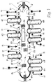
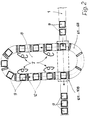
- a main conveyor 1 forms an oval on a flat corridor and thus encloses a surface 2. This surface 2 is accessible via a staircase 3 and a tunnel 4.
- the main conveyor 1 connects a number of automatic processing and / or assembly machines 51 to 59 and one Number of satellite conveyors 61 to 68, on which manual workstations 7 are arranged.
- the satellite conveyors 61 to 68 are also as flat Corrugated ovals are formed, each enclosing a surface 8.
- the main conveyor 1 and the satellite conveyors 61 to 68 convey workpiece carriers 9, which are automatically loaded with a basic equipment of material on the assembly machine 51.
- the workpiece carrier 9 with the possibly pre-fabricated and partially preassembled material placed by the assembly machine 51 is conveyed from the main conveyor 1 to a first workpiece transfer device 101, which connects the satellite conveyor 61 to the main conveyor 1.
- the workpiece transfer device 101 decides whether such work operations are required on the workpieces located on the workpiece carrier 9 that are carried out at work stations 7 of the satellite conveyor 61. This decision can be made possible by a coding of the workpiece carrier 9 which is known per se when the material is in contact with the assembly machine 51. If processing is provided at the work stations 7 of the satellite conveyor 61, then the workpiece carrier 9 is removed from a workpiece removal station of the workpiece transfer device 101 by the main conveyor 1, brought to the respective working height of the satellite conveyor 61 and placed there.
- the satellite conveyor 61 brings the workpiece carrier 9 together with the workpiece lying thereon to the successive workstations 7, the satellite conveyor 61 being able to convey continuously or step-wise depending on the type of these workstations 7.
- the workplaces for the workers who carry out the work operations at the work stations 7 are arranged within the area 8, so that a spatially closed work space is created for the work team.
- the additional materials and auxiliary materials required for these work operations are fed from outside of the surface 8 by a material feeder 11 and placed on material carriers 12. Access to the surfaces 8 can be via stairs or tunnels (not shown) or swiveling parts of the satellite conveyor.
- the transport system of the satellite conveyors can also be designed at such a height that it can be climbed comfortably.
- the respective workpiece carrier 9 again reaches the workpiece transfer device 101, where it is brought to the level of the main conveyor 1 and is converted back to the main conveyor 1 by a workpiece depositing station.
- the main conveyor 1 feeds the workpiece carrier 9 with the machined workpiece to the automatic processing and / or assembly machine 52 for further processing.
- the workpiece carrier 9 is now fed to the workpiece transfer device 102, in which the process for transfer to the satellite conveyor 62 is generally repeated in the same manner as described for the satellite conveyor 61.
- the workpiece transfer device 102 determines that the work operations of the work stations 7 arranged on the satellite conveyor 61 are not required for the workpiece currently present, for example by For example, if a particular unit is not to be attached to this workpiece, the workpiece carrier 9 is passed on from the workpiece transfer device 102 directly to the main conveyor 1, where it then meets the next processing or assembly machine 53, which is automated here.
- the processing or assembly of the workpiece, for. B. an internal combustion engine continues through the following automatic processing and / or assembly machines 54 to 59 and the workstations 7 within the satellite conveyor 63 to 68.
- the automatic processing or assembly machines 51 to 59 can be fed through material loading devices 13 material and auxiliary material are supplied.
- switch cabinets 14 for the control of the system as a whole and for the automatic processing and / or assembly machines 51 to 59 are accommodated.
- a service and maintenance center 15 is provided for the system within area 2.
- the finished workpiece e.g. B. the fully assembled internal combustion engine
- the workpiece carrier 8 runs via the main conveyor 1 again in the processing and / or assembly machine 51 into the circuit of the system.
- the invention enables a large number of exemplary embodiments.
- the arrangement of automatic processing or assembly machines and satellite conveyors can be varied as required.
- the main conveyor and the satellite conveyors can be designed as continuous conveyors or as step conveyors.
- the workpiece transfer devices can, as explained in the exemplary embodiment described above, each be provided with a workpiece removal station and a workpiece placement station, so that at the same time one workpiece is removed from the main conveyor and another is placed on it. However, they can also be equipped with a combined workpiece removal and placement station, so that one workpiece is removed from the main conveyor and another is placed one after the other.
- the system can be adapted well to the available space by appropriately designing the interior surfaces of main and satellite conveyors.
- the main conveyor can also be designed in such a way that only one line is accessible, that is, no area is delimited by it, and that the satellite conveyors connect to this line on one or both sides.
- the particular advantage of the invention is that with a processing and / or assembly system with a fixed configuration, work paths of different lengths and thus different work volumes can be realized side by side.
- the system can be arranged very compactly, so that only a relatively small footprint is required. Nevertheless, good working conditions with clear group formation are created for the people working on such a system.
- the adjustability of the working height on the satellite conveyors enables optimal ergonomic working conditions.
- the use of such a system can easily be set up for different capacities by means of variable staffing of the satellite conveyors, whereby an even workload for the workers is nevertheless ensured.
- the work operations covered by the satellite conveyors can optionally be omitted in the system. Defective workpieces can revolve a second time within each of the satellite conveyors in order to remedy the defect, so that no defective workpieces get onto the main conveyor.
Landscapes
- Engineering & Computer Science (AREA)
- Mechanical Engineering (AREA)
- Automatic Assembly (AREA)
- Electrical Discharge Machining, Electrochemical Machining, And Combined Machining (AREA)
- Paper (AREA)
- Multi-Process Working Machines And Systems (AREA)
- Pens And Brushes (AREA)
- Materials For Medical Uses (AREA)
Applications Claiming Priority (2)
| Application Number | Priority Date | Filing Date | Title |
|---|---|---|---|
| DE19514206 | 1995-04-15 | ||
| DE19514206A DE19514206A1 (de) | 1995-04-15 | 1995-04-15 | Bearbeitungs- und/oder Montageanlage |
Publications (3)
| Publication Number | Publication Date |
|---|---|
| EP0737543A2 true EP0737543A2 (fr) | 1996-10-16 |
| EP0737543A3 EP0737543A3 (fr) | 1997-10-29 |
| EP0737543B1 EP0737543B1 (fr) | 2002-06-19 |
Family
ID=7759759
Family Applications (1)
| Application Number | Title | Priority Date | Filing Date |
|---|---|---|---|
| EP96105340A Expired - Lifetime EP0737543B1 (fr) | 1995-04-15 | 1996-04-03 | Installation d'usinage et/ou de montage |
Country Status (7)
| Country | Link |
|---|---|
| EP (1) | EP0737543B1 (fr) |
| AT (1) | ATE219409T1 (fr) |
| BR (1) | BR9601368A (fr) |
| CZ (1) | CZ292142B6 (fr) |
| DE (2) | DE19514206A1 (fr) |
| ES (1) | ES2178686T3 (fr) |
| PT (1) | PT737543E (fr) |
Cited By (14)
| Publication number | Priority date | Publication date | Assignee | Title |
|---|---|---|---|---|
| WO1999037526A1 (fr) * | 1998-01-26 | 1999-07-29 | Thyssen Krupp Industries Ag | Procede pour la fabrication de portieres, de hayons ou de pieces en tole dans la coque de vehicules automobiles |
| WO2003074348A1 (fr) * | 2002-03-01 | 2003-09-12 | Bayerische Motoren Werke Aktiengesellschaft | Usine de montage servant au montage de produits industriels |
| WO2009047414A1 (fr) * | 2007-10-10 | 2009-04-16 | Peugeot Citroën Automobiles SA | Procede d'agrandissement d'un atelier de montage d'une usine de fabrication de vehicules automobiles et ateliers de montage associes |
| WO2012128705A1 (fr) * | 2011-03-21 | 2012-09-27 | Eton Ab | Poste de travail de transporteur |
| US8627558B2 (en) | 2007-12-05 | 2014-01-14 | Abb Research Ltd. | Production line and method for operating such |
| EP3214024A1 (fr) * | 2016-03-01 | 2017-09-06 | EWAB Engineering AB | Système de transporteur autonome |
| CN108015543A (zh) * | 2017-12-29 | 2018-05-11 | 安徽全柴动力股份有限公司 | 一种发动机活塞连杆总成内装线系统 |
| CN108515329A (zh) * | 2018-06-12 | 2018-09-11 | 广东大唐永恒智能科技有限公司 | 汽车头灯自动装配系统 |
| CN109605026A (zh) * | 2018-12-18 | 2019-04-12 | 昆山麦思创机械工业有限公司 | 基于柔性连接的组装检测一体式装配生产线 |
| CN109664115A (zh) * | 2018-12-29 | 2019-04-23 | 天津市天森智能设备有限公司 | 一种柔性制造系统 |
| CN110834061A (zh) * | 2019-12-09 | 2020-02-25 | 平湖市高嘉机械有限公司 | 多功能自动化除油联机装置 |
| CN112238913A (zh) * | 2019-07-19 | 2021-01-19 | 九号科技有限公司 | 组装生产线 |
| CN114981849A (zh) * | 2019-11-13 | 2022-08-30 | 捷德货币技术有限责任公司 | 用于处理有价文件的装置和方法 |
| US12005184B2 (en) | 2016-04-29 | 2024-06-11 | Rai Strategic Holdings, Inc. | Methods for assembling a cartridge for an aerosol delivery device, and associated systems and apparatuses |
Families Citing this family (3)
| Publication number | Priority date | Publication date | Assignee | Title |
|---|---|---|---|---|
| DE19752750A1 (de) * | 1997-11-28 | 1999-06-10 | Hennecke Gmbh | Vorrichtung zur Ein- und Ausschleusiung von an einer Kette umlaufenden Arbeitsstation |
| DE20112576U1 (de) * | 2001-07-31 | 2002-10-31 | KUKA Schweissanlagen GmbH, 86165 Augsburg | Fertigungsanlage |
| DE102021004658A1 (de) | 2021-09-14 | 2021-11-11 | Daimler Ag | System zur Prduktion von Elektrofahrzeugen |
Family Cites Families (12)
| Publication number | Priority date | Publication date | Assignee | Title |
|---|---|---|---|---|
| JPS5232137B2 (fr) * | 1971-12-29 | 1977-08-19 | ||
| JPS59209974A (ja) * | 1983-05-13 | 1984-11-28 | Daifuku Co Ltd | テストラインを含む搬送ラインでのエンジン搬送方法 |
| JPH0683938B2 (ja) * | 1984-07-09 | 1994-10-26 | マツダ株式会社 | 車両の組立ライン |
| DE3540316A1 (de) * | 1985-11-13 | 1987-05-14 | Siemens Ag | Fertigungsanlage zur automatischen montage und pruefung elektronischer flachbaugruppen |
| US5044541A (en) * | 1989-04-21 | 1991-09-03 | Nissan Motor Co., Ltd. | Method and apparatus for assembling vehicle body |
| FR2652293B1 (fr) * | 1989-09-22 | 1995-03-17 | Merlin Gerin | Machine de production incorporant un dispositif rapide d'amenage et de positionnement a double pas de pelerin, et systeme de production mettant en óoeuvre ce type de machine. |
| JPH03213473A (ja) * | 1990-01-17 | 1991-09-18 | Mazda Motor Corp | 自動車の前部車体組立方法 |
| DE4041239A1 (de) * | 1990-12-19 | 1992-07-02 | Siemens Ag | Fertigungseinrichtung fuer aus teilkomponenten zusammenfuegbare funktionseinheiten |
| DE69118499T2 (de) * | 1990-12-28 | 1996-11-07 | Mazda Motor | Methode zum Zusammenbau von Automobilen |
| DE9106962U1 (de) * | 1991-06-07 | 1992-10-08 | Altratec Montagesysteme GmbH, 71701 Schwieberdingen | Förderer von Gegenständen |
| JPH05181527A (ja) * | 1991-12-27 | 1993-07-23 | Mitsubishi Electric Corp | 自動搬送装置 |
| DE9315721U1 (de) * | 1993-10-15 | 1995-02-16 | Altratec GmbH Montagesysteme, 71701 Schwieberdingen | Transportstrecke |
-
1995
- 1995-04-15 DE DE19514206A patent/DE19514206A1/de not_active Withdrawn
-
1996
- 1996-04-03 ES ES96105340T patent/ES2178686T3/es not_active Expired - Lifetime
- 1996-04-03 PT PT96105340T patent/PT737543E/pt unknown
- 1996-04-03 AT AT96105340T patent/ATE219409T1/de not_active IP Right Cessation
- 1996-04-03 DE DE59609358T patent/DE59609358D1/de not_active Expired - Lifetime
- 1996-04-03 EP EP96105340A patent/EP0737543B1/fr not_active Expired - Lifetime
- 1996-04-15 CZ CZ19961089A patent/CZ292142B6/cs not_active IP Right Cessation
- 1996-04-15 BR BR9601368A patent/BR9601368A/pt not_active IP Right Cessation
Cited By (25)
| Publication number | Priority date | Publication date | Assignee | Title |
|---|---|---|---|---|
| WO1999037526A1 (fr) * | 1998-01-26 | 1999-07-29 | Thyssen Krupp Industries Ag | Procede pour la fabrication de portieres, de hayons ou de pieces en tole dans la coque de vehicules automobiles |
| WO2003074348A1 (fr) * | 2002-03-01 | 2003-09-12 | Bayerische Motoren Werke Aktiengesellschaft | Usine de montage servant au montage de produits industriels |
| CN100341740C (zh) * | 2002-03-01 | 2007-10-10 | 宝马股份公司 | 用于装配工业产品的装配厂 |
| WO2009047414A1 (fr) * | 2007-10-10 | 2009-04-16 | Peugeot Citroën Automobiles SA | Procede d'agrandissement d'un atelier de montage d'une usine de fabrication de vehicules automobiles et ateliers de montage associes |
| FR2922242A1 (fr) * | 2007-10-10 | 2009-04-17 | Peugeot Citroen Automobiles Sa | Procede d'agrandissement d'un atelier de montage d'une usine de fabrication de vehicules automobiles et ateliers de montage associes |
| CN101868400B (zh) * | 2007-10-10 | 2012-10-03 | 标致·雪铁龙汽车公司 | 机动车辆制造厂的装配车间和相关装配车间的扩建方法 |
| US8627558B2 (en) | 2007-12-05 | 2014-01-14 | Abb Research Ltd. | Production line and method for operating such |
| WO2012128705A1 (fr) * | 2011-03-21 | 2012-09-27 | Eton Ab | Poste de travail de transporteur |
| CN108778963A (zh) * | 2016-03-01 | 2018-11-09 | Ewab工程有限公司 | 自主输送机系统 |
| US10618742B2 (en) * | 2016-03-01 | 2020-04-14 | EWAB Engineering AB | Autonomous conveyor system |
| WO2017148863A1 (fr) * | 2016-03-01 | 2017-09-08 | EWAB Engineering AB | Système de transporteur autonome |
| US20190054587A1 (en) * | 2016-03-01 | 2019-02-21 | EWAB Engineering AB | Autonomous conveyor system |
| EP3214024A1 (fr) * | 2016-03-01 | 2017-09-06 | EWAB Engineering AB | Système de transporteur autonome |
| US12005184B2 (en) | 2016-04-29 | 2024-06-11 | Rai Strategic Holdings, Inc. | Methods for assembling a cartridge for an aerosol delivery device, and associated systems and apparatuses |
| US12564692B2 (en) | 2016-04-29 | 2026-03-03 | Rai Strategic Holdings, Inc. | Methods for assembling a cartridge for an aerosol delivery device, and associated systems and apparatuses |
| CN108015543A (zh) * | 2017-12-29 | 2018-05-11 | 安徽全柴动力股份有限公司 | 一种发动机活塞连杆总成内装线系统 |
| CN108015543B (zh) * | 2017-12-29 | 2023-08-29 | 安徽全柴动力股份有限公司 | 一种发动机活塞连杆总成内装线系统 |
| CN108515329A (zh) * | 2018-06-12 | 2018-09-11 | 广东大唐永恒智能科技有限公司 | 汽车头灯自动装配系统 |
| CN108515329B (zh) * | 2018-06-12 | 2023-10-31 | 广东大唐永恒智能科技有限公司 | 汽车头灯自动装配系统 |
| CN109605026A (zh) * | 2018-12-18 | 2019-04-12 | 昆山麦思创机械工业有限公司 | 基于柔性连接的组装检测一体式装配生产线 |
| CN109664115A (zh) * | 2018-12-29 | 2019-04-23 | 天津市天森智能设备有限公司 | 一种柔性制造系统 |
| CN112238913A (zh) * | 2019-07-19 | 2021-01-19 | 九号科技有限公司 | 组装生产线 |
| CN112238913B (zh) * | 2019-07-19 | 2025-09-23 | 九号科技有限公司 | 组装生产线 |
| CN114981849A (zh) * | 2019-11-13 | 2022-08-30 | 捷德货币技术有限责任公司 | 用于处理有价文件的装置和方法 |
| CN110834061A (zh) * | 2019-12-09 | 2020-02-25 | 平湖市高嘉机械有限公司 | 多功能自动化除油联机装置 |
Also Published As
| Publication number | Publication date |
|---|---|
| DE59609358D1 (de) | 2002-07-25 |
| CZ108996A3 (en) | 1997-09-17 |
| CZ292142B6 (cs) | 2003-08-13 |
| ATE219409T1 (de) | 2002-07-15 |
| EP0737543B1 (fr) | 2002-06-19 |
| BR9601368A (pt) | 1998-01-13 |
| PT737543E (pt) | 2002-11-29 |
| ES2178686T3 (es) | 2003-01-01 |
| DE19514206A1 (de) | 1996-10-17 |
| EP0737543A3 (fr) | 1997-10-29 |
Similar Documents
| Publication | Publication Date | Title |
|---|---|---|
| EP0737543B1 (fr) | Installation d'usinage et/ou de montage | |
| DE2760217C2 (fr) | ||
| EP1601492B1 (fr) | Installation de production de composants, en particulier de composants de carrosserie | |
| DE69502734T2 (de) | Montagewerkstatt für bleche | |
| DE102004053503B4 (de) | Honanlage mit mehreren Arbeitsstationen | |
| DE3409843C2 (de) | Verfahren und Anlage zum Herstellen von aus mehreren Teilen bestehenden Werkstücken | |
| EP0203170B1 (fr) | Systeme de fabrication flexible pour le traitement et la production d'ensembles a plusieurs parties, en particulier d'ensembles de carrosseries brutes | |
| EP2842892B1 (fr) | Système de chaînage pour des dispositifs de transfert en amont | |
| DE10112169B4 (de) | Verkettetes Fertigungssystem zur Durchführung von Bearbeitungsoperationen an Teilen | |
| EP0968073A1 (fr) | Procede et dispositif pour amener, serrer et usiner des pieces, en particulier pour le soudage geometrique de pieces de carrosseries automobiles dans une station d'usinage | |
| EP1100715A1 (fr) | Station de travail flexible et procede d'exploitation | |
| DE3606058A1 (de) | Schweissanlage fuer kraftfahrzeugkarosserien | |
| DE69935567T2 (de) | Bearbeitungssystem mit Späneförderer | |
| DE19713860A1 (de) | Verfahren und Vorrichtung zum Fertigen von komplexen Werkstücken | |
| DE4229067A1 (de) | Flexibles Transportsystem | |
| DE19505622A1 (de) | Anlage zum Zusammenbau von Kraftfahrzeugkarosserien | |
| EP2767461A1 (fr) | Dispositif de transport pour un dispositif de montage de véhicule | |
| DE2521787A1 (de) | Montagebandsystem | |
| DE60121941T2 (de) | Herstellungsverfahren und herstellungsanlage | |
| EP3199246B1 (fr) | Installation, module de traitement et procédé de traitement d'objets | |
| DE3902063C2 (fr) | ||
| DE4400099A1 (de) | Einzelpunkt Be- und Entladesystem für eine Doppelschlitten-Rotations-Blindkeilnuten- Räummaschine | |
| WO2007121697A1 (fr) | Système de fabrication comprenant l'interconnexion de stations de traitement par l'intermédiaire d'un module de transfert élevé | |
| DE4033184C2 (de) | Umlaufregallager-System | |
| DE4422380A1 (de) | Flexible Rohbaufertigungszelle für Karosseriebaugruppen |
Legal Events
| Date | Code | Title | Description |
|---|---|---|---|
| PUAI | Public reference made under article 153(3) epc to a published international application that has entered the european phase |
Free format text: ORIGINAL CODE: 0009012 |
|
| AK | Designated contracting states |
Kind code of ref document: A2 Designated state(s): AT DE ES FR GB IT PT |
|
| PUAL | Search report despatched |
Free format text: ORIGINAL CODE: 0009013 |
|
| AK | Designated contracting states |
Kind code of ref document: A3 Designated state(s): AT DE ES FR GB IT PT |
|
| 17P | Request for examination filed |
Effective date: 19980128 |
|
| 17Q | First examination report despatched |
Effective date: 20010227 |
|
| GRAG | Despatch of communication of intention to grant |
Free format text: ORIGINAL CODE: EPIDOS AGRA |
|
| GRAG | Despatch of communication of intention to grant |
Free format text: ORIGINAL CODE: EPIDOS AGRA |
|
| GRAH | Despatch of communication of intention to grant a patent |
Free format text: ORIGINAL CODE: EPIDOS IGRA |
|
| GRAH | Despatch of communication of intention to grant a patent |
Free format text: ORIGINAL CODE: EPIDOS IGRA |
|
| GRAA | (expected) grant |
Free format text: ORIGINAL CODE: 0009210 |
|
| AK | Designated contracting states |
Kind code of ref document: B1 Designated state(s): AT DE ES FR GB IT PT |
|
| REF | Corresponds to: |
Ref document number: 219409 Country of ref document: AT Date of ref document: 20020715 Kind code of ref document: T |
|
| REG | Reference to a national code |
Ref country code: GB Ref legal event code: FG4D Free format text: NOT ENGLISH |
|
| REF | Corresponds to: |
Ref document number: 59609358 Country of ref document: DE Date of ref document: 20020725 |
|
| GBT | Gb: translation of ep patent filed (gb section 77(6)(a)/1977) |
Effective date: 20020721 |
|
| REG | Reference to a national code |
Ref country code: PT Ref legal event code: SC4A Free format text: AVAILABILITY OF NATIONAL TRANSLATION Effective date: 20020918 |
|
| ET | Fr: translation filed | ||
| REG | Reference to a national code |
Ref country code: ES Ref legal event code: FG2A Ref document number: 2178686 Country of ref document: ES Kind code of ref document: T3 |
|
| PLBE | No opposition filed within time limit |
Free format text: ORIGINAL CODE: 0009261 |
|
| STAA | Information on the status of an ep patent application or granted ep patent |
Free format text: STATUS: NO OPPOSITION FILED WITHIN TIME LIMIT |
|
| 26N | No opposition filed |
Effective date: 20030320 |
|
| REG | Reference to a national code |
Ref country code: GB Ref legal event code: 732E Free format text: REGISTERED BETWEEN 20090219 AND 20090225 |
|
| REG | Reference to a national code |
Ref country code: GB Ref legal event code: 732E Free format text: REGISTERED BETWEEN 20090305 AND 20090311 |
|
| PGFP | Annual fee paid to national office [announced via postgrant information from national office to epo] |
Ref country code: PT Payment date: 20090330 Year of fee payment: 14 |
|
| PGFP | Annual fee paid to national office [announced via postgrant information from national office to epo] |
Ref country code: ES Payment date: 20090508 Year of fee payment: 14 |
|
| PGFP | Annual fee paid to national office [announced via postgrant information from national office to epo] |
Ref country code: IT Payment date: 20090423 Year of fee payment: 14 Ref country code: AT Payment date: 20090415 Year of fee payment: 14 |
|
| REG | Reference to a national code |
Ref country code: GB Ref legal event code: 732E Free format text: REGISTERED BETWEEN 20091029 AND 20091104 |
|
| REG | Reference to a national code |
Ref country code: GB Ref legal event code: 732E Free format text: REGISTERED BETWEEN 20091105 AND 20091111 |
|
| PG25 | Lapsed in a contracting state [announced via postgrant information from national office to epo] |
Ref country code: AT Free format text: LAPSE BECAUSE OF NON-PAYMENT OF DUE FEES Effective date: 20100403 |
|
| PG25 | Lapsed in a contracting state [announced via postgrant information from national office to epo] |
Ref country code: PT Free format text: LAPSE BECAUSE OF NON-PAYMENT OF DUE FEES Effective date: 20101004 |
|
| PG25 | Lapsed in a contracting state [announced via postgrant information from national office to epo] |
Ref country code: IT Free format text: LAPSE BECAUSE OF NON-PAYMENT OF DUE FEES Effective date: 20100403 |
|
| REG | Reference to a national code |
Ref country code: DE Ref legal event code: R081 Ref document number: 59609358 Country of ref document: DE Owner name: GM GLOBAL TECHNOLOGY OPERATIONS LLC (N. D. GES, US Free format text: FORMER OWNER: GM GLOBAL TECHNOLOGY OPERATIONS, INC., DETROIT, MICH., US Effective date: 20110323 Ref country code: DE Ref legal event code: R081 Ref document number: 59609358 Country of ref document: DE Owner name: GM GLOBAL TECHNOLOGY OPERATIONS LLC (N. D. GES, US Free format text: FORMER OWNER: GM GLOBAL TECHNOLOGY OPERATIONS, INC., DETROIT, US Effective date: 20110323 |
|
| REG | Reference to a national code |
Ref country code: ES Ref legal event code: FD2A Effective date: 20110715 |
|
| PG25 | Lapsed in a contracting state [announced via postgrant information from national office to epo] |
Ref country code: ES Free format text: LAPSE BECAUSE OF NON-PAYMENT OF DUE FEES Effective date: 20110705 |
|
| PG25 | Lapsed in a contracting state [announced via postgrant information from national office to epo] |
Ref country code: ES Free format text: LAPSE BECAUSE OF NON-PAYMENT OF DUE FEES Effective date: 20100404 |
|
| PGFP | Annual fee paid to national office [announced via postgrant information from national office to epo] |
Ref country code: GB Payment date: 20120328 Year of fee payment: 17 |
|
| PGFP | Annual fee paid to national office [announced via postgrant information from national office to epo] |
Ref country code: DE Payment date: 20120419 Year of fee payment: 17 |
|
| PGFP | Annual fee paid to national office [announced via postgrant information from national office to epo] |
Ref country code: FR Payment date: 20120504 Year of fee payment: 17 |
|
| GBPC | Gb: european patent ceased through non-payment of renewal fee |
Effective date: 20130403 |
|
| PG25 | Lapsed in a contracting state [announced via postgrant information from national office to epo] |
Ref country code: GB Free format text: LAPSE BECAUSE OF NON-PAYMENT OF DUE FEES Effective date: 20130403 Ref country code: DE Free format text: LAPSE BECAUSE OF NON-PAYMENT OF DUE FEES Effective date: 20131101 |
|
| REG | Reference to a national code |
Ref country code: FR Ref legal event code: ST Effective date: 20131231 |
|
| REG | Reference to a national code |
Ref country code: DE Ref legal event code: R119 Ref document number: 59609358 Country of ref document: DE Effective date: 20131101 |
|
| PG25 | Lapsed in a contracting state [announced via postgrant information from national office to epo] |
Ref country code: FR Free format text: LAPSE BECAUSE OF NON-PAYMENT OF DUE FEES Effective date: 20130430 |