EP0737577B1 - Dispositif de nettoyage pour une machine d'impression à stencil - Google Patents
Dispositif de nettoyage pour une machine d'impression à stencil Download PDFInfo
- Publication number
- EP0737577B1 EP0737577B1 EP96302547A EP96302547A EP0737577B1 EP 0737577 B1 EP0737577 B1 EP 0737577B1 EP 96302547 A EP96302547 A EP 96302547A EP 96302547 A EP96302547 A EP 96302547A EP 0737577 B1 EP0737577 B1 EP 0737577B1
- Authority
- EP
- European Patent Office
- Prior art keywords
- contact
- excessive
- printing
- contact member
- removing liquid
- Prior art date
- Legal status (The legal status is an assumption and is not a legal conclusion. Google has not performed a legal analysis and makes no representation as to the accuracy of the status listed.)
- Expired - Lifetime
Links
Images



Classifications
-
- B—PERFORMING OPERATIONS; TRANSPORTING
- B41—PRINTING; LINING MACHINES; TYPEWRITERS; STAMPS
- B41F—PRINTING MACHINES OR PRESSES
- B41F35/00—Cleaning arrangements or devices
-
- B—PERFORMING OPERATIONS; TRANSPORTING
- B41—PRINTING; LINING MACHINES; TYPEWRITERS; STAMPS
- B41P—INDEXING SCHEME RELATING TO PRINTING, LINING MACHINES, TYPEWRITERS, AND TO STAMPS
- B41P2235/00—Cleaning
- B41P2235/10—Cleaning characterised by the methods or devices
- B41P2235/20—Wiping devices
- B41P2235/21—Scrapers, e.g. absorbent pads
-
- B—PERFORMING OPERATIONS; TRANSPORTING
- B41—PRINTING; LINING MACHINES; TYPEWRITERS; STAMPS
- B41P—INDEXING SCHEME RELATING TO PRINTING, LINING MACHINES, TYPEWRITERS, AND TO STAMPS
- B41P2235/00—Cleaning
- B41P2235/10—Cleaning characterised by the methods or devices
- B41P2235/20—Wiping devices
- B41P2235/23—Brushes
-
- B—PERFORMING OPERATIONS; TRANSPORTING
- B41—PRINTING; LINING MACHINES; TYPEWRITERS; STAMPS
- B41P—INDEXING SCHEME RELATING TO PRINTING, LINING MACHINES, TYPEWRITERS, AND TO STAMPS
- B41P2235/00—Cleaning
- B41P2235/30—Recovering used solvents or residues
-
- B—PERFORMING OPERATIONS; TRANSPORTING
- B65—CONVEYING; PACKING; STORING; HANDLING THIN OR FILAMENTARY MATERIAL
- B65H—HANDLING THIN OR FILAMENTARY MATERIAL, e.g. SHEETS, WEBS, CABLES
- B65H2301/00—Handling processes for sheets or webs
- B65H2301/50—Auxiliary process performed during handling process
- B65H2301/53—Auxiliary process performed during handling process for acting on performance of handling machine
- B65H2301/531—Cleaning parts of handling machine
Definitions
- the present invention relates to a print image treatment device used in a stencil printing device or the like.
- the present invention is effective as a measure particularly for a set-off and seeping-through in printing.
- a set-off a phenomenon that a printing ink having formed a print image on a printed body sticks to the back surface of another placed thereon, when printed bodies are piled up immediately after printing; print image deformation occurring when a finger gives a slight touch on a print image surface immediately after printing; and seeping-through, a phenomenon that a printing ink having formed a print image on a printed body penetrates through the printed body to the back surface.
- a fine powder such as starch or talc can be applied to a print image for preventing a set-off.
- a device as applies these fine powders uses compressed air; a printing device having this type of device is apt to become considerably large.
- a conveyer belt has been used to transfer a printed body by a transfer mechanism coming in touch only with the back surface (non-printed surface) of the printed body.
- the printed body transfer device of this type has been disclosed in, for instance, Japanese Patent Laid-Open No. 50-88769.
- the inventors of the present invention have devised a new device that removes an excessive printing ink from a printed body to enhance the quality of printing.
- This device comprises a contact roller on the surface of which an excessive ink removing liquid is applied in a layered form while rotating, and a facing roller rotating face to face with the contact roller; and nips to carry the printed body by the contact roller and facing roller. It transfers the excessive printing ink of a print image on the printed body to the excessive ink removing liquid applied in a layered form on the contact roller; the excessive printing ink on the contact roller is removed by a cleaning means such as a blade in contact with the contact roller.
- the above-mentioned device uses for an excessive ink removing liquid a fluid not dissolving the ink and having a lower surface tension than that of the printing ink, and applies this fluid in a layered form onto the contact roller.
- the printing ink having been transferred to the contact roller will pass through the cleaning means such as a blade and again come into contact with the print image surface, leading to blurring the print image surface.
- the cleaning means such as a blade was not effective enough for performing a perfect cleaning; it was found necessary to disperse the excessive printing ink having transferred to the contact roller into the excessive ink removing liquid.
- the present invention intends to improve the aforementioned excessive ink removing device based on the inventors' proposition; aiming at reliably preventing a set-off, seeping-through or the like from occurring on the printed body without other faults induced; and therefore, it is an object of the present invention to provide a print image treatment device capable of removing the excessive printing ink of the print image reliably, and not blurring the print image when the contact roller comes again into contact with the print image on the printed body.
- the cleaning means may be a plate member being in contact with a surface of the contact member in front of the top, in the rotating direction of the contact member.
- the supply means may supply the excessive ink removing liquid on a surface of the contact member in front of the contact position formed by the cleaning means and the contact member, in the rotating direction of the contact member.
- a recovery means for recovering the excessive ink removing liquid may be provided in contact with a surface of the contact member in front of the contact position formed by the cleaning means and the contact member, in the rotating direction of the contact member.
- the front end of the recovery means may come into close contact with a surface of the contact member with a specified length, and the rear end be placed at a lower position than that of the front end to guide downward the excessive ink removing liquid on the surface of the contact member.
- the contact member may be comprised of an endless belt loaded on a plurality of rollers.
- the contact member may be a contact roller to nip the printed body already printed between the facing member and the contact member.
- a copy reader which calculates the printing rate of a copy in advance of printing
- a supply control means determines the quantity of the excessive ink removing liquid based on the printing rate of a copy calculated by the copy reader and the excessive printing ink rate representing the rate of the excessive printing ink quantity against the printing ink quantity having been transferred onto the printed body and supplies it from the supply means, and, optionally, the supply control means may control the quantity of the excessive ink removing liquid per unit time to be supplied to the contact means so as to be larger than one third of the printing Ink quantity per unit time transferred onto the contact member , and/or the printing may be the stencil printing, and the excessive printing ink rate 10 - 30 %.
- the present invention has at least the following actions
- the excessive ink removing liquid applied on the surface of the contact member comes into contact with the surface of the print image on the printed body.
- the excessive part of the printing ink forming the print image is transferred into the excessive ink removing liquid on the contact member, and is removed from the printed body.
- the excessive ink removing liquid does not dissolve in the printing ink forming the print image, and is a liquid having a lower surface tension than that of the printing ink.
- the excessive printing ink transferred into the excessive ink removing liquid is in a floating state on the surface of the excessive ink removing liquid.
- the excessive printing ink being in a floating state on the surface of the contact member is removed from the contact member with the excessive ink removing liquid by the cleaning means being in contact with the surface of the contact member; and it is dispersed into the excessive ink removing liquid standing between the cleaning means and the contact member.
- This dispersion Is composed of an emulsion of the excessive ink removing liquid of the outer phase and the printing ink of the inner phase. Therefore, the printing ink contained in the excessive ink removing liquid will not pass through the cleaning means; the printing ink on the contact means will reliably be removed.
- a copy image reader 5 has an image scanner 3 to read a copy image for printing and performs a specific image processing.
- a perforator 9 has a perforating device 7 to form a perforated image on a stencil sheet S for the stencil printing according to a copy image data read by the copy image reader 5. As described later, the printing rate of a copy is given by the copy image reader 5.
- the stencil sheet S for the stencil printing perforated by the perforator 9 is wound up around the circumference of a cylindrical printing drum 13.
- an ink supplier 11 including an ink squeegee Is installed to supply an ink to the inner surface of the printing drum 13.
- a press roller 15 movable up and down is placed under the printing drum 13.
- the press roller 15 and the printing drum 13 nip and carry a printed body P supplied between them, forming a print image on the printed body P, (e.g. a sheet, such as a printing paper).
- a paper feeder roller 19 feeds sheet by sheet the printed body P placed on a paper supply table 17, and the printed body P is fed into between the press roller 15 and the printing drum 13 by a paper supply timing roller 21.
- a sheet separater claw 25 peels off the printed body P from the printing drum 13.
- the printed body P having been peeled off is carried to the print image after treatment device 29 by a conveyer 27 having a belt conveying mechanism.
- the print image treatment device 29 removes an excessive ink from the printed image on the printed body P.
- the printed body P having been treated is discharged and piled up onto a paper receiving tray 31.
- the stencil sheet S for the stencil printing having completed a printing is taken off from the printing drum 13 by a stencil disposal part 35, and is disposed.
- the printing drum 13 rotates around its central axis in the anticlockwise direction in the drawing, being driven by a driving means as not illustrated in the drawing.
- the printed body P is carried, at a given timing synchronized with the rotation of the printing drum 13, from left to right in the drawing by the paper supply timing roller 21, and is fed into a portion between the printing drum 13 and the press roller 15.
- the printed body P is pressed by the press roller 15 toward the stencil sheet S wound around on the circumference of the printing drum 13, on which the stencil printing is applied.
- the printed body P already printed is peeled off from the printing drum 13 by the sheet separater claw 25 and is guided to the print image treatment device 29 with the print image upward by the conveyer 27 for conveying a paper.
- the printed body P is treated by the print image treatment device 29, and is carried to the paper receiving tray 31 and piled up thereon.
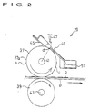
- the print image treatment device 29 has a contact roller 37 for the contact member which comes into contact with the print image surface on the printed body P already printed, and a facing roller 39 for the facing member placed face to face with the contact roller 37.
- the contact roller 37 and the facing roller 39 are supported by a spindle 41 and 43 in parallel and rotatably, respectively.
- the facing roller 39 is forced upward, toward the contact roller 37 by a spring as an forcing means as not illustrated in the drawing.
- a blade 45 a plate member having an approximately rectangular cross section is in contact with a circumference 37a (surface of an excessive ink removing liquid applied) of the contact roller 37.
- the base end of the blade 45 is fixed at an end of a metal member, the front end of the blade 45 is in contact with the contact roller 37.
- the contact roller 37, facing roller 39, and blade 45 are comprised of a material which does not create changes in quality such as swelling by the excessive ink removing liquid.
- the contact roller 37, facing roller 39, and blade 45 are preferably comprised of a fluorocarbon resin (rubber) to reduce the friction coefficient with the contact roller 37; but the materials are not particularly confined to a phenyl metamorphic silicon resin (rubber) or the like.
- An excessive ink removing liquid supplying nozzle 47 is placed in front of the position where the contact roller 37 is in contact with the blade 45 In the rotating direction, above the circumference 37a of the contact roller 37.
- the excessive ink removing liquid supplying nozzle 47 is a means for supplying the excessive ink removing liquid onto the circumference 37a of the contact roller 37.
- the excessive ink removing liquid does not dissolve in the printing ink which forms the print image, and has a lover surface tension than the printing ink.
- the excessive ink removing liquid supplying nozzle 47 supplies the excessive ink removing liquid onto the circumference 37a of the contact roller 37
- the excessive ink removing liquid stands between the blade 45 and the contact roller 37.
- the excessive ink removing liquid passes through between the contact roller 37 and the blade 45 forming a layer on the surface of the contact roller 37.
- the blade 45 functions so as to unify the quantity of the excessive ink removing liquid applied on the circumference 37a of the contact roller 37.
- the blade 45 functions as a cleaning means for removing dirt on the circumference 37a of the contact roller 37.
- the excessive ink removing liquid used in this embodiment does not dissolve in the printing ink which forms the print image on the print image surface of the printed body P, and is a liquid having a lower surface tension than that of the printing ink.
- There are liquids to meet this condition for instance, dimethyl-siliconoil, and modified-siliconoil with phenyl, polyether, fluorine, amino, epoxy, carboxyl, carbinol, methacryl, mercapto, or phenol to be used for the excessive ink removing liquid.
- the excessive ink removing liquid mentioned above is particularly effective for a water-in-oil type emulsion ink.
- aqueous solutions with a surface active agent or an organic solvent added can be used for the excessive ink remover.
- a surface active agent to be added in water there are anion, cation, and ampholytic ionic and nonionic surface active agents.
- the addition rate of each of these surface active agents is determined so that the surface tension of the excessive ink removing liquid is lower than that of the printing ink.
- a water-soluble organic solvent there are methanol, ethanol, isopropyl alcohol, n-isopropyl alcohol, ethylene, glycol, and glycerin.
- the excessive ink removing liquid and the excessive printing ink applied on the contact roller 37 can not flow smoothly due to the blade 45 together with the rotation of the contact roller 37. Only a small portion of them can pass through between the blade 45 and the contact roller 37; a large majority of them stay making a puddle in front of the blade 45 upstream in the rotating direction.
- the excessive printing ink transferred to the contact roller 37 from the printed body P is dispersed in the excessive ink removing liquid at the fluid puddle (f).
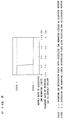
- the quantity of the excessive ink removing liquid standing at the fluid puddle (f) must be larger than one third of that of the excessive printing ink thereat.
- the quantity of the excessive ink removing liquid per unit time from the excessive ink removing liquid supplying nozzle 47 is set to being larger than one third of the printing ink per unit time transferred to the contact roller 37. This is controlled by the supply control means.
- Fig. 3 is a graph illustrating the relation between the quantity of the excessive ink removing liquid at the fluid puddle (f) and the printing ink quantity transferred to the contact roller 37.
- an excessive ink removing liquid dispersion fluid When the quantity of the excessive ink removing liquid becomes smaller than one third of the printing ink quantity, an excessive ink removing liquid dispersion fluid will be formed while having the printing ink as a disperse medium. In this state, the excessive ink removing liquid dispersion fluid passes through the blade 45, and again blurs the print image by transferring to the print image.
- a sheet elastic body 49 is slanted in front of the blade 45 in the rotating direction of the contact roller 37, as a recovery means for the excessive ink removing liquid.
- the rear end of the sheet elastic body 49 is fixed at a receiver 51 for the excessive ink removing liquid, placed at a lower position than that of the aforementioned contact point (d).
- the action of the print image treatment device 29 constituted as above will now be described.
- the contact roller 37 and the facing roller 39 nip and carry the printed body P already printed.
- the film (a) of the excessive ink removing liquid formed on the circumference 37a of the contact roller 37 comes in contact with the print image surface on the printed body P.
- This contact transfers the excessive part of the printing ink ( b ) forming the print image on the printed body P to the film ( a ) of the excessive ink removing liquid on the contact roller 37; the excessive part of the printing ink is removed from the printed body P.
- the printing ink (c) having been transferred to the film (a) of the excessive ink removing liquid on the contact roller 37 passes through a part where the sheet elastic body 49 and the contact roller 37 slide In contact with each other with the rotation of the contact roller 37.
- the excessive ink removing liquid used for this embodiment does not dissolve in the printing ink (b) forming the print image, and is a liquid having a lower surface tension than that of the printing ink (c).
- the supply control means controls the quantity of the excessive ink removing liquid at the fluid puddle (f) so as to set it to always being larger than one third of the quantity of the printing ink.
- the fluid puddle (f) is composed of an emulsion by the excessive ink removing liquid of the outer phase and the printing ink of the inner phase.
- the printing ink of the inner phase is in a free floating state, locationally separated from the excessive ink removing liquid of the outer phase.
- the contact roller 37 rotates keeping in contact with the blade 45. Taking a microscopical look at the contact part, contacts and gaps are seen aggregated. Since the size of the gaps is smaller than the diameter of most particles of the printing ink in the mixed fluid at the fluid puddle (f), the particles of the printing ink can not pass through, and the excessive ink removing liquid of the outer phase passes through the gaps.
- the printed body P passes through between the contact roller 37 and the facing roller 39; the excessive part of the printing ink (b) forming the print image is reliably removed from the circumference 37a of the contact roller 37. Consequently, the occurrence of the set-off or seeping-through reduces in the printed body already printed.
- the print image surface is touched by a finger or the like immediately after being discharged, the print image becomes immune from being deformed, and drying the printing ink (b) forming the print image can be done in a shorter time.
- the quantity of the excessive ink removing liquid to be supplied to the fluid puddle (f) needs to be changed corresponding to the quantity of the printing ink transferred to the printed body P by a printing machine.
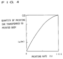
- the transfer quantity of the printing ink to the printed body P by a printing machine changes according to the printing rate (area perforated / area allowable of printing).
- This printing rate is acquired by the copy reader 5 for reading the copy and processing the print image, when the perforating of a stencil sheet S for a stencil printing is conducted according to the copy at the perforator 9 in advance of printing operation.
- the excessive printing ink on the printed body P amounts to 10 - 30% of all the quantity of the printing ink having been transferred to the printed body P; this is an excessive printing ink rate.
- the quantity of the excessive ink removing liquid to be supplied to the fluid puddle (f) is determined by the printing rate judged by the copy reader 5 and the excessive printing ink rate (maximum value fixed at 30% of the total quantity of the printing ink having been transferred to the printed body P).
- the quantity of the printing ink transferred to the contact roller 37 will be determined.
- the supply control means calculates the quantity of the foregoing excessive ink removing liquid and supplies the excessive ink removing liquid to the contact roller 37 so that the quantity to be supplied to the fluid puddle (f) will become equal to the calculated quantity.
- the quantity per unit time of the excessive ink removing liquid supplied by the excessive ink removing liquid supplying nozzle 47 is set to being larger than one third of the quantity per unit time of the printing ink transferred to the contact roller 37, the printing ink will not pass through the gaps between the contact roller 37 and the blade 45 and will be removed reliably.
- an application roller 60 is installed in contact with the contact roller 37, in replacement of the excessive ink supplying nozzle 47 as a supply means.
- the application roller 60 rotates as the contact roller 37 rotates.
- the application roller 60 has a cylindrical form, holds the excessive ink removing liquid inside, and supplies the excessive ink removing liquid to the contact roller 37 by a constant quantity through small holes formed on Its circumference.
- an application member 60a made of a paper, nonwoven fabric, woven fabric, or the like is wound up; the excessive Ink removing liquid penetrating out from inside is applied uniformly through the application member 60a. This mode of the embodiment will produce a similar effect to the foregoing embodiment.
- a flexible endless belt 57 for a contact member is put on to bridge two rollers 53 and 55 placed separately in an upper and a lower position, with a certain tension applied.
- This mode of the embodiment will produce a similar effect to the foregoing embodiment.
- the contact member such as the contact roller having the excessive ink removing liquid in a layer on its surface comes into contact with the print image surface on a printing paper.
- This contact will completely remove the excessive part of the printing ink forming the print image on the printed body; and therefore, the set-off or the seeping-through will reliably be prevented without other defects induced, and the print image will hardly be deformed by finger-rubbing directly after the printed body having been discharged.
- the excessive ink removing liquid does not dissolve in the printing ink forming the print image , and is a liquid having a lower tension than that of the printing ink; and therefore, an emulsion is formed at the fluid puddle by the excessive ink removing liquid of the outer phase and the printing ink of the inner phase.
- the printing ink will not pass through the gaps between the contact member and the blade as a cleaning means and can be peeled off from the surface of the contact roller; therefore, the printed body will not be blurred.
Landscapes
- Printing Methods (AREA)
- Supply, Installation And Extraction Of Printed Sheets Or Plates (AREA)
Claims (10)
- Dispositif de traitement d'image imprimée (29) destiné à traiter une image imprimée formée par une encre d'impression comprenant:un élément de contact (37) pouvant en être entraíné en rotation, sur la surface duquel est appliqué un liquide d'élimination d'excès d'encre qui ne se dissout pas dans l'encre d'impression constituant inne image imprimée et qui présente une tension superficielle inférieure à celle de l'encre d'impression; un élément en regard (39) destiné à amener une surface imprimée d'un corps imprimé (P) en contact avec le liquide d'élimination d'excès d'encre sur l'élément de contact (37) en appliquant et en transportant le corps imprimé (P) qui a été imprimé entre l'élément de contact (37) et l'élément en regard (39); un moyen d'alimentation (47) destiné à délivrer le liquide d'élimination d'excès d'encre a l'élément de contact (37); un moyen de nettoyage (45) destiné à éliminer le liquide d'élimination d'excès d'encre et l'encre d'impression, glissant en contact sur l'élément de contact (37); un mélange din liquide d'élimination d'excès d'encre (f) et de l'encre d'impression à un emplacement en amont dans le sens de la rotation par rapport à la partie de contact formée par l'élément de contact (37) et le moyen de nettoyage (45) sur l'élément de contact (37), le moyen d'alimentation (47) étant agencé de manière à maintenir un état dans lequel la quantité de liquide d'élimination d'excès d'encre dans le mélange est supérieure à un tiers de celle de l'encre d'impression.
- Dispositif de traitement d'image imprimée selon la revendication 1, dans lequel le moyen de nettoyage est constitué par un élément en plaque (45) en contact avec une surface de l'élément de contact (37) face à la partie supérieure de l'élément de contact (37), dans le sens de la rotation de l'élément de contact (37).
- Dispositif de traitement d'image imprimée selon les revendications 1 ou 2, dans lequel le moyen d'alimentation (47) est agencé afin de délivrer le liquide d'élimination d'excès d'encre sur une surface de l'élément de contact (37) face à l'emplacement de contact formé par le moyen de nettoyage (45) et l'élément de contact (37) dans le sens de la rotation de l'élément de contact (37).
- Dispositif de traitement d'image imprimée selon les revendications 1, 2 ou 3, dans lequel un moyen de récupération (49) destiné à récupérer le liquide d'élimination d'excès d'encre est en contact avec une surface de l'élément de contact (37) face à l'emplacement de contact formé par le moyen de nettoyage (45) et l'élément de contact (37), dans le sens de la rotation de l'élément de contact (37).
- Dispositif de traitement d'image imprimée selon la revendication 4, dans lequel l'extrémité avant du moyen de récupération (49) vient en contact étroit avec une surface de l'élément de contact (37) sur une longueur spécifiée, et l'extrémité arrière est placée à un emplacement inférieur à celui de l'extrémité avant afin de guider vers le bas le liquide d'élimination d'excès d'encre sur la surface de l'élément de contact (37).
- Dispositif de traitement d'image imprimée selon l'une quelconque des revendications précédentes, dans lequel l'élément de contact est une courroie sans fin (57) chargée sur une pluralité de rouleaux (53, 55).
- Dispositif de traitement d'image imprimée selon l'une quelconque des revendications 1 à 5, dans lequel l'élément de contact est un rouleau de contact (37) destiné à pincer le corps imprimé, après impression, entre l'élément en regard (39) et l'élément de contact (37).
- Dispositif de traitement d'image imprimée selon l'une quelconque des revendications précédentes comprenant, en outre: un lecteur de copie destiné à calculer le rapport d'impression d'une copie en préalable de l'impression; et un moyen de commande d'alimentation destiné à déterminer la quantité de liquide d'élimination d'excès d'encre en fonction du rapport d'impression d'une copie, calculé par le lecteur de copie, et du rapport d'excès d'encre d'impression, représentant le rapport entre la quantité d'encre d'impression en excès et la quantité d'encre d'impression qui a été transférée sur le corps imprimé (P), et agencé de manière que le moyen d'alimentation (47) délivre celle-ci.
- Dispositif de traitement d'image imprimée selon la revendication 8, dans lequel le moyen de commande d'alimentation commande la quantité de liquide d'élimination excès d'encre par unité de temps sur le moyen de contact (37) de telle manière qu'elle est supérieure à un tiers de la quantité d'encre d'impression par unité de temps transférée sur l'élément de contact (37).
- Dispositif de traitement d'image imprimée selon la revendication 8 ou 9, dans lequel l'impression est une impression par stencil et le rapport d'excès d'encre d'impression est compris entre 10 et 30%.
Applications Claiming Priority (4)
| Application Number | Priority Date | Filing Date | Title |
|---|---|---|---|
| JP88379/95 | 1995-04-13 | ||
| JP8837995 | 1995-04-13 | ||
| JP41631/96 | 1996-02-28 | ||
| JP8041631A JPH08336951A (ja) | 1995-04-13 | 1996-02-28 | 印刷画像後処理装置 |
Publications (2)
| Publication Number | Publication Date |
|---|---|
| EP0737577A1 EP0737577A1 (fr) | 1996-10-16 |
| EP0737577B1 true EP0737577B1 (fr) | 1999-01-07 |
Family
ID=26381275
Family Applications (1)
| Application Number | Title | Priority Date | Filing Date |
|---|---|---|---|
| EP96302547A Expired - Lifetime EP0737577B1 (fr) | 1995-04-13 | 1996-04-11 | Dispositif de nettoyage pour une machine d'impression à stencil |
Country Status (4)
| Country | Link |
|---|---|
| US (1) | US5671675A (fr) |
| EP (1) | EP0737577B1 (fr) |
| JP (1) | JPH08336951A (fr) |
| DE (1) | DE69601279T2 (fr) |
Families Citing this family (5)
| Publication number | Priority date | Publication date | Assignee | Title |
|---|---|---|---|---|
| JPH106633A (ja) * | 1996-06-20 | 1998-01-13 | Riso Kagaku Corp | 印刷画像後処理装置 |
| NL1007246C2 (nl) * | 1997-08-26 | 1999-03-01 | Stork Brabant Bv | Drukinrichting met kleefstofrakel. |
| NL1010934C2 (nl) * | 1998-12-31 | 2000-07-03 | Neopost Bv | Inrichting voor het separeren van vellen. |
| FI108285B (fi) * | 1999-01-07 | 2001-12-31 | Erpico Oy | Ylimääräisen painovärin poistolaite |
| US6955721B2 (en) * | 2002-02-28 | 2005-10-18 | Lexmark International, Inc. | System and method of coating print media in an inkjet printer |
Family Cites Families (7)
| Publication number | Priority date | Publication date | Assignee | Title |
|---|---|---|---|---|
| US3861351A (en) * | 1973-12-06 | 1975-01-21 | Dusenbery Co John | Apparatus for coating and stacking printed sheets |
| JPS59203028A (ja) * | 1983-05-04 | 1984-11-17 | Canon Inc | 両面複写装置の回転給紙部材のクリ−ニング装置 |
| JPS60204543A (ja) * | 1984-03-30 | 1985-10-16 | Matsushita Graphic Commun Syst Inc | 自動給紙装置 |
| JPS63149155A (ja) * | 1986-12-15 | 1988-06-21 | Hitachi Seiko Ltd | グラビヤ輪転印刷機 |
| JPS63268649A (ja) * | 1987-04-27 | 1988-11-07 | Nikka Kk | 輪転印刷機のガイドロ−ラ拭浄方法 |
| US4836129A (en) * | 1987-06-26 | 1989-06-06 | Epic Products International Corp. | Apparatus for coating a web with wet ink thereon |
| US5476043A (en) * | 1993-09-16 | 1995-12-19 | Riso Kagaku Corporation | Method and device for post-processing a printed image in a printing device |
-
1996
- 1996-02-28 JP JP8041631A patent/JPH08336951A/ja active Pending
- 1996-04-05 US US08/627,354 patent/US5671675A/en not_active Expired - Lifetime
- 1996-04-11 DE DE69601279T patent/DE69601279T2/de not_active Expired - Lifetime
- 1996-04-11 EP EP96302547A patent/EP0737577B1/fr not_active Expired - Lifetime
Also Published As
| Publication number | Publication date |
|---|---|
| US5671675A (en) | 1997-09-30 |
| JPH08336951A (ja) | 1996-12-24 |
| DE69601279D1 (de) | 1999-02-18 |
| EP0737577A1 (fr) | 1996-10-16 |
| DE69601279T2 (de) | 1999-06-02 |
Similar Documents
| Publication | Publication Date | Title |
|---|---|---|
| US5476043A (en) | Method and device for post-processing a printed image in a printing device | |
| JP2764067B2 (ja) | 像保持体からの像形成物質除去方法及びその装置 | |
| US5671675A (en) | Print image treatment device | |
| EP0734868B1 (fr) | Dispositif de traitement d'image d'impression | |
| US5694840A (en) | Printing image after-processing apparatus | |
| EP0734869B1 (fr) | Dispositif de traitement d'image d'impression | |
| JP3367772B2 (ja) | 印刷画像後処理装置 | |
| JP3363260B2 (ja) | 孔版印刷装置の印刷画像後処理方法および装置 | |
| JP3367771B2 (ja) | 印刷画像後処理装置 | |
| EP0813975B1 (fr) | Dispositif de traitement d'une feuille imprimée | |
| JP3518840B2 (ja) | 像保持体の再生装置 | |
| JP3367769B2 (ja) | 印刷画像面処理装置 | |
| JPH08281910A (ja) | 印刷画像後処理装置 | |
| JPH08267712A (ja) | 印刷画像後処理装置 | |
| JPH08258244A (ja) | 印刷画像後処理装置 | |
| JPH08281909A (ja) | 印刷装置及び印刷画像後処理装置 | |
| JPH08202221A (ja) | 像保持体からの像形成物質除去装置 | |
| JP2005231075A (ja) | インキ供給装置及びフレキソ印刷機 | |
| JPH08267708A (ja) | 印刷画像後処理装置 | |
| JPH08267711A (ja) | 印刷画像後処理装置 | |
| JPH11277719A (ja) | 印刷物のインキ除去方法、印刷物のインキ除去装置、印刷装置 | |
| JPH08267707A (ja) | 印刷画像後処理装置 | |
| JPH08276565A (ja) | 印刷画像後処理装置 | |
| JPH08281911A (ja) | 印刷画像後処理装置 | |
| JPH09311577A (ja) | 電子写真式画像形成装置の定着装置 |
Legal Events
| Date | Code | Title | Description |
|---|---|---|---|
| PUAI | Public reference made under article 153(3) epc to a published international application that has entered the european phase |
Free format text: ORIGINAL CODE: 0009012 |
|
| AK | Designated contracting states |
Kind code of ref document: A1 Designated state(s): DE FR GB |
|
| 17P | Request for examination filed |
Effective date: 19960916 |
|
| 17Q | First examination report despatched |
Effective date: 19970722 |
|
| GRAG | Despatch of communication of intention to grant |
Free format text: ORIGINAL CODE: EPIDOS AGRA |
|
| GRAG | Despatch of communication of intention to grant |
Free format text: ORIGINAL CODE: EPIDOS AGRA |
|
| GRAH | Despatch of communication of intention to grant a patent |
Free format text: ORIGINAL CODE: EPIDOS IGRA |
|
| GRAH | Despatch of communication of intention to grant a patent |
Free format text: ORIGINAL CODE: EPIDOS IGRA |
|
| GRAA | (expected) grant |
Free format text: ORIGINAL CODE: 0009210 |
|
| AK | Designated contracting states |
Kind code of ref document: B1 Designated state(s): DE FR GB |
|
| REF | Corresponds to: |
Ref document number: 69601279 Country of ref document: DE Date of ref document: 19990218 |
|
| ET | Fr: translation filed | ||
| PLBE | No opposition filed within time limit |
Free format text: ORIGINAL CODE: 0009261 |
|
| STAA | Information on the status of an ep patent application or granted ep patent |
Free format text: STATUS: NO OPPOSITION FILED WITHIN TIME LIMIT |
|
| 26N | No opposition filed | ||
| REG | Reference to a national code |
Ref country code: GB Ref legal event code: IF02 |
|
| PGFP | Annual fee paid to national office [announced via postgrant information from national office to epo] |
Ref country code: DE Payment date: 20120425 Year of fee payment: 17 |
|
| PGFP | Annual fee paid to national office [announced via postgrant information from national office to epo] |
Ref country code: GB Payment date: 20120411 Year of fee payment: 17 Ref country code: FR Payment date: 20120504 Year of fee payment: 17 |
|
| GBPC | Gb: european patent ceased through non-payment of renewal fee |
Effective date: 20130411 |
|
| PG25 | Lapsed in a contracting state [announced via postgrant information from national office to epo] |
Ref country code: GB Free format text: LAPSE BECAUSE OF NON-PAYMENT OF DUE FEES Effective date: 20130411 Ref country code: DE Free format text: LAPSE BECAUSE OF NON-PAYMENT OF DUE FEES Effective date: 20131101 |
|
| REG | Reference to a national code |
Ref country code: FR Ref legal event code: ST Effective date: 20131231 |
|
| REG | Reference to a national code |
Ref country code: DE Ref legal event code: R119 Ref document number: 69601279 Country of ref document: DE Effective date: 20131101 |
|
| PG25 | Lapsed in a contracting state [announced via postgrant information from national office to epo] |
Ref country code: FR Free format text: LAPSE BECAUSE OF NON-PAYMENT OF DUE FEES Effective date: 20130430 |