EP0737628B1 - Vorrichtung zum Aufbewahren und Ausgeben eines flüssigen oder pastösen Produktes - Google Patents
Vorrichtung zum Aufbewahren und Ausgeben eines flüssigen oder pastösen Produktes Download PDFInfo
- Publication number
- EP0737628B1 EP0737628B1 EP96400789A EP96400789A EP0737628B1 EP 0737628 B1 EP0737628 B1 EP 0737628B1 EP 96400789 A EP96400789 A EP 96400789A EP 96400789 A EP96400789 A EP 96400789A EP 0737628 B1 EP0737628 B1 EP 0737628B1
- Authority
- EP
- European Patent Office
- Prior art keywords
- membrane
- receptacle
- nozzle
- internal
- punt
- Prior art date
- Legal status (The legal status is an assumption and is not a legal conclusion. Google has not performed a legal analysis and makes no representation as to the accuracy of the status listed.)
- Expired - Lifetime
Links
- 239000007788 liquid Substances 0.000 title claims description 5
- 235000011837 pasties Nutrition 0.000 title description 4
- 239000012528 membrane Substances 0.000 claims abstract description 23
- 238000004806 packaging method and process Methods 0.000 claims abstract description 7
- 230000002093 peripheral effect Effects 0.000 claims description 10
- 239000000126 substance Substances 0.000 claims 4
- 238000007789 sealing Methods 0.000 abstract description 3
- 239000000047 product Substances 0.000 description 18
- 241001573881 Corolla Species 0.000 description 6
- 230000006835 compression Effects 0.000 description 4
- 238000007906 compression Methods 0.000 description 4
- 230000000903 blocking effect Effects 0.000 description 3
- 238000007790 scraping Methods 0.000 description 3
- 230000000295 complement effect Effects 0.000 description 1
- 239000002537 cosmetic Substances 0.000 description 1
- 239000006071 cream Substances 0.000 description 1
- 230000008034 disappearance Effects 0.000 description 1
- 230000000694 effects Effects 0.000 description 1
- 230000005489 elastic deformation Effects 0.000 description 1
- 239000012263 liquid product Substances 0.000 description 1
- 239000000463 material Substances 0.000 description 1
- 239000002184 metal Substances 0.000 description 1
- 238000000034 method Methods 0.000 description 1
Images

Classifications
-
- B—PERFORMING OPERATIONS; TRANSPORTING
- B05—SPRAYING OR ATOMISING IN GENERAL; APPLYING FLUENT MATERIALS TO SURFACES, IN GENERAL
- B05B—SPRAYING APPARATUS; ATOMISING APPARATUS; NOZZLES
- B05B11/00—Single-unit hand-held apparatus in which flow of contents is produced by the muscular force of the operator at the moment of use
- B05B11/01—Single-unit hand-held apparatus in which flow of contents is produced by the muscular force of the operator at the moment of use characterised by the means producing the flow
- B05B11/10—Pump arrangements for transferring the contents from the container to a pump chamber by a sucking effect and forcing the contents out through the dispensing nozzle
- B05B11/1042—Components or details
- B05B11/1073—Springs
- B05B11/1076—Traction springs, e.g. stretchable sleeve
-
- B—PERFORMING OPERATIONS; TRANSPORTING
- B05—SPRAYING OR ATOMISING IN GENERAL; APPLYING FLUENT MATERIALS TO SURFACES, IN GENERAL
- B05B—SPRAYING APPARATUS; ATOMISING APPARATUS; NOZZLES
- B05B11/00—Single-unit hand-held apparatus in which flow of contents is produced by the muscular force of the operator at the moment of use
- B05B11/01—Single-unit hand-held apparatus in which flow of contents is produced by the muscular force of the operator at the moment of use characterised by the means producing the flow
- B05B11/10—Pump arrangements for transferring the contents from the container to a pump chamber by a sucking effect and forcing the contents out through the dispensing nozzle
- B05B11/1094—Pump arrangements for transferring the contents from the container to a pump chamber by a sucking effect and forcing the contents out through the dispensing nozzle having inlet or outlet valves not being actuated by pressure or having no inlet or outlet valve
-
- B—PERFORMING OPERATIONS; TRANSPORTING
- B65—CONVEYING; PACKING; STORING; HANDLING THIN OR FILAMENTARY MATERIAL
- B65D—CONTAINERS FOR STORAGE OR TRANSPORT OF ARTICLES OR MATERIALS, e.g. BAGS, BARRELS, BOTTLES, BOXES, CANS, CARTONS, CRATES, DRUMS, JARS, TANKS, HOPPERS, FORWARDING CONTAINERS; ACCESSORIES, CLOSURES, OR FITTINGS THEREFOR; PACKAGING ELEMENTS; PACKAGES
- B65D83/00—Containers or packages with special means for dispensing contents
- B65D83/76—Containers or packages with special means for dispensing contents for dispensing fluent contents by means of a piston
- B65D83/765—Containers or packages with special means for dispensing contents for dispensing fluent contents by means of a piston the piston being a follower-piston and the dispensing means comprising a hand-operated pressure device at the opposite part of the container
-
- B—PERFORMING OPERATIONS; TRANSPORTING
- B05—SPRAYING OR ATOMISING IN GENERAL; APPLYING FLUENT MATERIALS TO SURFACES, IN GENERAL
- B05B—SPRAYING APPARATUS; ATOMISING APPARATUS; NOZZLES
- B05B11/00—Single-unit hand-held apparatus in which flow of contents is produced by the muscular force of the operator at the moment of use
- B05B11/01—Single-unit hand-held apparatus in which flow of contents is produced by the muscular force of the operator at the moment of use characterised by the means producing the flow
- B05B11/02—Membranes or pistons acting on the contents inside the container, e.g. follower pistons
- B05B11/028—Pistons separating the content remaining in the container from the atmospheric air to compensate underpressure inside the container
Definitions
- the present invention relates to a device for packaging and distribution of a liquid or pasty product.
- packaging and distribution systems which include in particular means for compressing a product in a container, tightly closed, on the one hand at its part upper by a cover axially traversed by a nozzle tube the upper end of which protrudes outside and, on the other hand, at its lower part by an internally movable bottom.
- the means of compression generally consist of a pump fitted with a spring.
- the object of the present invention is to solve the problems previous techniques satisfactorily.
- a device for packaging and dispensing a liquid product or pasty comprising in particular means for compressing a container sealed on the one hand at its upper part by a cover axially overturned by a tube forming a nozzle, the upper end protrudes on the outside and, on the other hand, at its part lower by an internally movable bottom, characterized in that said compression means comprise a membrane elastically deformable, pierced with a central ejection orifice which is housed in the upper part of the container and in that the end internal lower part of the nozzle is provided on the one hand with a support element on said membrane and, on the other hand, a sealing element of said ejection port.
- said membrane is consisting of a substantially frustoconical axial valve whose the upper end is provided with the ejection orifice and the edge of which lower is attached to a U-shaped section ring extending towards the high, along the inner wall of the container by a thin skirt extendable connected at its upper part to a mounting flange on the recipient.
- said cover covers the upper part of the container by trapping the fixing flange of said membrane.
- said support element of the nozzle on the membrane consists of a peripheral corolla surrounding the shutter element.
- the lower edge of said corolla is preferably made up of a tapered crown.
- said element closing the ejection orifice consists of a central lug delimiting around it a cavity communicating with the conduit internal nozzle by at least one lateral opening.
- said movable bottom is consisting of a sliding element towards the nozzle and self-locking of substantially cylindrical shape having on the one hand an upper wall, elastically deformable convex, intended to be constantly at product contact and, on the other hand, a peripheral side wall intended to come into bracing against the internal lateral face of the container.
- the peripheral edge of the upper wall of the movable bottom has a profile ensuring both the scraping of the product on the internal lateral face of the container when raising the bottom and the bottom seal of the container.
- the movable bottom comprises at besides under its upper wall a crown of flexible lamellae inclined downwards, the ends of which bear against the face internal container to reinforce the blocking of the bottom.
- the upper end of the nozzle tube is capped by a dispensing nozzle.
- the device of the invention is particularly simple because it consists only of a small number of parts.
- This device has no metal parts and can therefore be easily recycled.
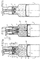
- the device shown in Figures 1a, 1b and 1c is intended for packaging and distribution of a liquid or pasty product P.
- This product can therefore have a high viscosity and be present in form of a cream.
- the device notably comprises compression means of a product P in a container 1 so as to allow the ejection of the product P.
- the container 1 is sealed on the one hand, at its upper part by a cover 2 and, on the other hand, at its lower part by an internally movable bottom 5.
- the cover 2 is crossed axially by a tube 3 forming a nozzle.
- the upper end 31 of the tube 3 and its internal duct 31a protrude and open to the outside.
- a dispensing tip 6 comes to cap the upper end of the tube 3 above the cover 2.
- the means of compressing the product P in the container 1 include an elastically deformable membrane 4.
- the membrane 4 is pierced with a central ejection orifice 41 and is housed in the upper part of container 1.
- the membrane 4 consists of an axial valve 40 substantially frustoconical, the upper end of which is provided with the ejection orifice 41 and the lower edge of which is attached to a ring 42 of U-shaped section.
- the ring 42 extends upwards, along the inner wall of container 1 by a thin, extendable skirt 43, connected at its upper part with an annular flange 44 for fixing on the container 1.
- the annular flange 44 preferably comprises a shoulder 45 intended to marry the neck 10 of the container 1.
- the cover 2 covers the neck 10 while being in support on the flange 44 and trapping the shoulder 45 of the flange 44 between its lateral wall and the external face of the neck 10.
- the lower edge of the cover 2 is in abutment against a shoulder 11 of the container 1 and is fitted in force on a span cylindrical 12 formed on the neck 10 of the container above shoulder 11.
- the internal lower end of the nozzle tube 3 is provided on the one hand, of a support element on the membrane 4 and, on the other hand, of a closure element of the ejection orifice 41.
- the support element of the inner lower end of the tube 3 on the membrane 4 consists of a peripheral corolla 32 surrounding the closing element of the orifice 41.
- the lower edge of the corolla 32 has a crown frustoconical 32a in contact with support on the ring 42.
- Crown 32a has a larger width and diameter than the upper part of the corolla 32 to guarantee a bearing force uniform on the ring 42.
- the closure element of the ejection orifice 41 is constituted a central lug 33 defining around it a cavity 34 communicating with the internal conduit 31a of the tube 3 by at least one lateral opening 35.
- the movable bottom 5 consists of a sliding element towards the high in the direction of the nozzle and self-locking substantially shaped cylindrical.
- This element has, on the one hand, an upper wall 51, convex and elastically deformable intended to be constantly in contact with the product 2 and, on the other hand, a peripheral side wall 52 intended to come into bracing against the internal lateral face of the container 1 so to prohibit the return of the bottom 5 to the bottom.
- the peripheral edge 50 of the upper wall 51 of the bottom mobile 5 has a profile ensuring both the scraping of the product P on the face internal lateral of the container 1 during the raising of the bottom 5 and the sealing bottom of said container.
- the manual pressure F exerted on the nozzle 6 causes the descent of the tube 3 and the support of the crown 32a of the corolla 32 on the ring 42, which causes the elongation of the skirt 43 of the membrane 4 and the compression of the product P in container 1 by the piston effect of ring 42.
- the overpressure created within product P causes the opening of the ejection orifice 41 around the lug 33, the filling of the cavity 34 and the expulsion of the product P outside, via the internal conduit 31a of the tube 3.
- the quantity of product distributed is therefore a direct function of the lengthening of the skirt 43.
- the overpressure created inside the container 1 causes also elastic deformation and, more precisely, flattening of the convex upper wall 51 of the bottom 5. This deformation is affects the peripheral edge 50 of the wall 51 by pressing reinforced then prohibiting any descent from the bottom 5. Simultaneously, we witness the erasure of the side wall 52 and the disappearance temporary bracing.
- the bottom 5 slides in a guided way upwards by sliding of its lateral wall 52 against the internal lateral face of the container 1. This movement is made possible by the temporary absence of bracing and is accompanied by scraping of the internal lateral face of the container.
- the bottom mobile 5 further comprises, under its upper wall 51, a crown flexible strips 53 inclined downwards. The free ends of strips 53 come to bear against the internal face of the container 1 for reinforce the hold of the bottom in its blocking position.
- the blade crown 53 is fixed to a central bush 54 integral with the upper wall 51 and projecting downward.
Landscapes
- Engineering & Computer Science (AREA)
- Mechanical Engineering (AREA)
- Closures For Containers (AREA)
- Containers And Packaging Bodies Having A Special Means To Remove Contents (AREA)
- Jellies, Jams, And Syrups (AREA)
- Fertilizing (AREA)
- Control And Other Processes For Unpacking Of Materials (AREA)
Claims (9)
- Vorrichtung zur Konditionierung und Verteilung eines flüssigen oder pastenformigen Produkts (P), welche insbesondere eine elastisch verformbare Membran (4) umfasst, die mit einer Ausstoßöffnung (41) versehen ist, welche im oberen Teil eines Behälters (1) für das Produkt (P) vorgesehen ist, der einerseits in seinem oberen Teil durch eine Abdeckhaube (2), durch welche ein Rohr (3) axial durchgeht, das eine Spritzdüse bildet, deren oberes Ende (31) nach außen absteht und deren inneres unteres Ende mit einem Element zur Auflage auf der Membran (4) und mit einem Element zum Verschließen der Ausstoßöffnung (41) versehen ist, und andererseits in seinem unteren Teil durch einen innen beweglichen Boden (5) dicht verschlossen ist, dadurch gekennzeichnet, dass die Membran (4) von einer im wesentlichen kegelstumpfförmigen axialen Klappe (40) gebildet ist, deren oberes Ende mit der Ausstoßöffnung (41) versehen ist und deren unterer Rand an einem Ring (42) von U-förmigem Querschnitt befestigt ist, der entlang der Innenwand des Behälters (1) durch einen erweiterbaren dünnen Mantel (43) nach oben hin verlängert ist, welcher in seinem oberen Teil mit einem Flansch (44) zur Befestigung am Behälter (1) verbunden ist.
- Vorrichtung nach Anspruch 1, dadurch gekennzeichnet, dass die Abdeckhaube (2) den oberen Teil des Behälters (1) unter Festhalten des Befestigungsflansches (44) der Membran (4) überdeckt.
- Vorrichtung nach einem der vorhergehenden Ansprüche, dadurch gekennzeichnet, dass das Element zur Auflage der Spritzdüse (3) auf der Membran (4) durch eine das Verschließorgan umgebende periphere Krone (32) gebildet ist.
- Vorrichtung nach Anspruch 3, dadurch gekennzeichnet, dass der untere Rand der Krone (32) einen kegelstumpfförmigen Kranz (32a) aufweist.
- Vorrichtung nach einem der vorhergehenden Ansprüche, dadurch gekennzeichnet, dass das Verschließorgan der Ausstoßöffnung (41) durch einen zentralen Stift (33) gebildet ist, der um sich herum einen Hohlraum (34) begrenzt, welcher über mindestens eine seitliche Öffnung (35) mit der Innenleitung (31a) der Spritzdüse (3) kommuniziert.
- Vorrichtung nach einem der vorhergehenden Ansprüche, dadurch gekennzeichnet, dass der bewegliche Boden (5) durch ein in Richtung zur Spritzdüse verschiebbares und selbsthemmendes Element von im wesentlichen zylindrischer Form gebildet ist, das einerseits eine elastisch verformbare, konvexe obere Wand (51), die dazu bestimmt ist, in ständigem Kontakt mit dem Produkt (P) zu stehen, und andererseits eine periphere Seitenwand (52), die dazu bestimmt ist, an der inneren Seitenfläche des Behälters (1) in bogenförmige Verstrebung zu kommen, aufweist.
- Vorrichtung nach Anspruch 6, dadurch gekennzeichnet, dass der Umfangsrand (50) der oberen Wand (51) des beweglichen Bodens (5) ein Profil aufweist, das gleichzeitig ein Abstreifen des Produkts (P) von der inneren Seitenwand des Behälters (1) beim Hochgehen des Bodens (5) und die untere Dichtheit des Behälters gewährleistet.
- Vorrichtung nach Anspruch 6 oder 7, dadurch gekennzeichnet, dass der bewegliche Boden (5) weiters unterhalb seiner oberen Wand (51) einen Kranz aus nach unten geneigten nachgiebigen Lamellen (53) aufweist, deren Enden zur Verstärkung der Hemmung des Bodens (5) in Anlage an der Innenseite des Behälters (1) kommen.
- Vorrichtung nach einem der vorhergehenden Ansprüche, dadurch gekennzeichnet, dass das obere Ende (31) des Spritzdüsenrohrs (31) von einem Ausgießer (6) überdeckt ist.
Applications Claiming Priority (3)
| Application Number | Priority Date | Filing Date | Title |
|---|---|---|---|
| FR9504452A FR2732950B1 (fr) | 1995-04-13 | 1995-04-13 | Dispositif pour le conditionnement et la distribution d'un produit liquide ou pateux |
| FR9504452 | 1995-04-13 | ||
| CA002174022A CA2174022A1 (en) | 1995-04-13 | 1997-04-12 | A device for packaging and dispensing a liquid or semi-liquid substance |
Publications (2)
| Publication Number | Publication Date |
|---|---|
| EP0737628A1 EP0737628A1 (de) | 1996-10-16 |
| EP0737628B1 true EP0737628B1 (de) | 2000-07-26 |
Family
ID=32825872
Family Applications (1)
| Application Number | Title | Priority Date | Filing Date |
|---|---|---|---|
| EP96400789A Expired - Lifetime EP0737628B1 (de) | 1995-04-13 | 1996-04-12 | Vorrichtung zum Aufbewahren und Ausgeben eines flüssigen oder pastösen Produktes |
Country Status (11)
| Country | Link |
|---|---|
| US (1) | US5788124A (de) |
| EP (1) | EP0737628B1 (de) |
| JP (1) | JP3544786B2 (de) |
| AT (1) | ATE194956T1 (de) |
| CA (2) | CA2176283A1 (de) |
| DE (1) | DE69609440T2 (de) |
| DK (1) | DK0737628T3 (de) |
| ES (1) | ES2150643T3 (de) |
| FR (1) | FR2732950B1 (de) |
| GR (1) | GR3034691T3 (de) |
| PT (1) | PT737628E (de) |
Families Citing this family (33)
| Publication number | Priority date | Publication date | Assignee | Title |
|---|---|---|---|---|
| FR2786467B1 (fr) * | 1998-11-27 | 2001-02-02 | Lir France Sa | Dispositif de distribution de produits liquides, fluides ou pateux |
| FR2786754B1 (fr) * | 1998-12-04 | 2001-02-02 | Lir France Sa | Distributeur de produits liquides, fluides ou pateux |
| FR2796672B1 (fr) * | 1999-07-19 | 2001-10-12 | Oreal | Pompe a membrane avec bossage annulaire d'etancheite, et recipient ainsi equipe |
| FR2800132B1 (fr) * | 1999-10-26 | 2002-03-08 | Oreal | POMPE DESTINEE A EQUIPER UN RECIPIENT, COMPORTANT UNE MEMBRANE ELASTIQUEMENT DEFORMABLE A l'EXTERIEUR DE LA CHAMBRE DE POMPAGE |
| FR2805183B1 (fr) * | 2000-02-23 | 2002-12-27 | Oreal | Pompe comportant une membrane formant ressort et recipient ainsi equipe |
| US6375045B1 (en) * | 2000-03-30 | 2002-04-23 | Yonwoo Corporation | Airless type dispenser |
| US6632681B1 (en) | 2000-07-24 | 2003-10-14 | Ey Laboratories | Reagent delivery device and method of use |
| US6382472B1 (en) * | 2001-03-07 | 2002-05-07 | Doron Shoval | Viscous fluid dispenser |
| FR2852302B1 (fr) * | 2003-03-13 | 2006-07-14 | Valois Sas | Organe de distribution de produit fluide et distributeur de produit fluide comprenant un tel organe |
| US6945435B2 (en) * | 2003-04-17 | 2005-09-20 | Helen Of Troy Limited | User-refillable liquid dispensing container with vacuum actuated piston |
| FR2863595B1 (fr) * | 2003-12-12 | 2006-03-03 | Airlessystems | Distributeur de produit fluide. |
| SE526936C2 (sv) * | 2004-04-01 | 2005-11-22 | A2 Acoustics Ab | Anordning för vibrationsstyrning i motorfordon på så sätt att önskad vibrationskaraktär i ratten erhålles |
| FR2884877B1 (fr) * | 2005-04-21 | 2010-09-03 | Rexam Dispensing Sys | Pompe pour distributeur de produit fluide dont le corps presente une collerette d'assemblage et d'etancheite |
| FR2907035B1 (fr) * | 2006-10-12 | 2010-08-27 | Gerard Sannier | Dispositif de production de mousse renversable et rechargeable |
| FR2911123B1 (fr) * | 2007-01-10 | 2012-08-03 | Valois Sas | Piston suiveur, reservoir et distributeur comprenant un tel piston |
| US8262592B1 (en) | 2007-12-27 | 2012-09-11 | Brooks Ray G | Fluid dispenser |
| JP2010022559A (ja) * | 2008-07-18 | 2010-02-04 | Canon Inc | 液体容器、及びこれを備えた吸入装置 |
| WO2010082771A2 (ko) * | 2009-01-14 | 2010-07-22 | Kang Sungil | 내용물 배출펌프 |
| CN102336308B (zh) * | 2010-07-26 | 2014-02-19 | 方祥铭 | 推挤取料式储料容器 |
| DE202010011248U1 (de) * | 2010-08-08 | 2011-09-01 | Anton Brugger | Dosierspender |
| EP2655893B1 (de) * | 2010-12-21 | 2020-02-05 | Silgan Dispensing Systems Corporation | Pumpvorrichtungen |
| RU2601453C2 (ru) * | 2011-06-09 | 2016-11-10 | Айропак Текнолоджи Груп Аг | Насосное устройство для контейнера, предназначенного для текучей среды |
| KR101378369B1 (ko) * | 2011-06-14 | 2014-03-27 | (주)연우 | 펌핑식 화장품용기 |
| CN103350821B (zh) * | 2013-07-01 | 2015-10-28 | 深圳市通产丽星股份有限公司 | 一种真空分配器 |
| US10144032B2 (en) * | 2013-12-20 | 2018-12-04 | Toaster Labs, Inc. | Inductively heatable fluid reservoir |
| US9801505B2 (en) | 2013-12-20 | 2017-10-31 | Toaster Labs, Inc. | Automatic fluid dispenser |
| US10433372B2 (en) | 2013-12-20 | 2019-10-01 | Toaster Labs, Inc. | Portable fluid warming device |
| US9974416B2 (en) | 2013-12-20 | 2018-05-22 | Toaster Labs, Inc. | Automatic heated fluid dispenser |
| US10189038B2 (en) | 2013-12-20 | 2019-01-29 | Toaster Labs, Inc. | Inductively heatable fluid reservoir for various fluid types |
| US10098510B2 (en) | 2013-12-20 | 2018-10-16 | Toaster Loabs, Inc. | Pneumatically driven fluid dispenser |
| FR3047187B1 (fr) * | 2016-02-01 | 2020-02-28 | Albea Lacrost | Dispositif d'aspiration de produit liquide dans un distributeur |
| CN109178625B (zh) * | 2018-10-12 | 2019-06-18 | 广州市莲娜姬化妆品有限公司 | 一种节约环保的按压泵瓶子及方法 |
| EP4470676A1 (de) | 2023-06-02 | 2024-12-04 | Aptar Radolfzell GmbH | Pumpeneinheit und flüssigkeitsspender mit einer solchen pumpeneinheit |
Family Cites Families (10)
| Publication number | Priority date | Publication date | Assignee | Title |
|---|---|---|---|---|
| US4452379A (en) * | 1982-07-09 | 1984-06-05 | Bundschuh Robert L | Pump dispenser with one-piece stretchable biasing member and valve |
| DE3601311A1 (de) * | 1986-01-17 | 1987-07-23 | Joachim Czech | Spender fuer pastoese produkte |
| US5174478A (en) * | 1986-02-07 | 1992-12-29 | Reyman Mark E | Device for the controlled measuring and dispensing of a fluid |
| GB8629982D0 (en) * | 1986-12-16 | 1987-01-28 | English Glass Co Ltd | Dispenser pump |
| IT210199Z2 (it) * | 1987-04-10 | 1988-12-06 | Guala Angelo Spa | Dispensatore di prodotti pastosi in generale e di pasta dentifricia in particolare, con membrana pompante comandata a leva. |
| DE3928524C2 (de) * | 1989-08-29 | 1994-02-24 | Megaplast Dosiersysteme | Spender |
| FR2674024B1 (fr) * | 1991-03-11 | 1994-03-11 | Daniel Crosnier | Dispositif doseur adaptable sur des contenants divers. |
| US5518147A (en) * | 1994-03-01 | 1996-05-21 | The Procter & Gamble Company | Collapsible pump chamber having predetermined collapsing pattern |
| US5476195A (en) * | 1994-10-06 | 1995-12-19 | Procter & Gamble Company | Pump device with collapsible pump chamber and including dunnage means |
| US5544789A (en) * | 1995-01-05 | 1996-08-13 | Calmar Inc. | Bellows pump dispenser |
-
1995
- 1995-04-13 FR FR9504452A patent/FR2732950B1/fr not_active Expired - Lifetime
-
1996
- 1996-04-12 EP EP96400789A patent/EP0737628B1/de not_active Expired - Lifetime
- 1996-04-12 DK DK96400789T patent/DK0737628T3/da active
- 1996-04-12 DE DE69609440T patent/DE69609440T2/de not_active Expired - Fee Related
- 1996-04-12 PT PT96400789T patent/PT737628E/pt unknown
- 1996-04-12 US US08/631,001 patent/US5788124A/en not_active Expired - Fee Related
- 1996-04-12 ES ES96400789T patent/ES2150643T3/es not_active Expired - Lifetime
- 1996-04-12 AT AT96400789T patent/ATE194956T1/de not_active IP Right Cessation
- 1996-04-15 JP JP11524696A patent/JP3544786B2/ja not_active Expired - Fee Related
- 1996-05-10 CA CA002176283A patent/CA2176283A1/en not_active Abandoned
-
1997
- 1997-04-12 CA CA002174022A patent/CA2174022A1/en not_active Abandoned
-
2000
- 2000-10-26 GR GR20000402378T patent/GR3034691T3/el not_active IP Right Cessation
Also Published As
| Publication number | Publication date |
|---|---|
| ATE194956T1 (de) | 2000-08-15 |
| JP3544786B2 (ja) | 2004-07-21 |
| ES2150643T3 (es) | 2000-12-01 |
| EP0737628A1 (de) | 1996-10-16 |
| DK0737628T3 (da) | 2000-12-18 |
| CA2176283A1 (en) | 1996-10-14 |
| DE69609440T2 (de) | 2001-03-15 |
| GR3034691T3 (en) | 2001-01-31 |
| PT737628E (pt) | 2001-01-31 |
| FR2732950A1 (fr) | 1996-10-18 |
| CA2174022A1 (en) | 1998-10-12 |
| FR2732950B1 (fr) | 1997-07-04 |
| JPH092512A (ja) | 1997-01-07 |
| US5788124A (en) | 1998-08-04 |
| DE69609440D1 (de) | 2000-08-31 |
Similar Documents
| Publication | Publication Date | Title |
|---|---|---|
| EP0737628A1 (de) | Vorrichtung zum Aufbewahren und Ausgeben eines flüssigen oder pastösen Produktes | |
| EP0696480B1 (de) | Membranpumpe | |
| EP1205403B1 (de) | Einheit zur Aufbewahrung und Ausgabe eines unter Druck stehenden Produktes | |
| FR2809776A1 (fr) | Pompe a membrane | |
| EP0874761B1 (de) | Ausgiesser für flüssige oder pastöse produkte | |
| EP0765822B1 (de) | Vorrichtung mit Sicherheitsventil zur Ausgabe von flüssigen Produkten unter Druck | |
| EP0945367A1 (de) | Abgabebehälter für Flüssigkeiten in Form einer Flasche, mit einem an ein Steigrohr ausschliessenden Abgabeorgan | |
| EP1165247B1 (de) | Pumpe mit rücksaugeffekt | |
| FR2714892A1 (fr) | Dispositif de conditionnement et de distribution d'un produit liquide. | |
| EP1671705B1 (de) | Mit einer Pumpe ausgestatteter Kunststoffspender | |
| EP2397422B1 (de) | Fluidspendesystem | |
| EP0477083B1 (de) | Vordruck-Handpumpe | |
| FR2630712A1 (fr) | Recipient a dispositif distributeur pour produit liquide ou pateux | |
| EP1412093B1 (de) | Einen dosierstab bildender spender für flüssige oder gelartige produkte | |
| EP1379442B1 (de) | Vorrichtung zur dosierten abgabe von flüssigen oder gelförmigen medien | |
| FR2779205A1 (fr) | Valve et ensemble de conditionnement et de distribution equipe d'une telle valve | |
| EP0605275B1 (de) | Anordnung zur Zerstäubung einer Flüssigkeit mit einer Vordruckpumpe | |
| EP0452437B1 (de) | Automatisches ventil | |
| FR2692040A1 (fr) | Dispositif doseur pour substance fluide. | |
| FR2612889A1 (fr) | Tete de dosage pour recipients sous pression a valve continue | |
| CH635297A5 (fr) | Dispositif de fermeture a buse basculable, notamment pour recipient pressurise. | |
| FR2814727A1 (fr) | Valve destinee a equiper un dispositif pour la distribution sous pression d'un produit, et dispositif ainsi equipe | |
| FR2891531A1 (fr) | Dispositif de delivrance a installer sur un recipient. | |
| FR2773537A1 (fr) | Dispositif de distribution adaptable sur un flacon contenant une poudre | |
| FR2496598A3 (fr) | Bidon en matiere plastique, notamment pour cyclistes |
Legal Events
| Date | Code | Title | Description |
|---|---|---|---|
| PUAI | Public reference made under article 153(3) epc to a published international application that has entered the european phase |
Free format text: ORIGINAL CODE: 0009012 |
|
| AK | Designated contracting states |
Kind code of ref document: A1 Designated state(s): AT BE CH DE DK ES FI FR GB GR IE IT LI LU MC NL PT SE |
|
| 17P | Request for examination filed |
Effective date: 19970304 |
|
| GRAG | Despatch of communication of intention to grant |
Free format text: ORIGINAL CODE: EPIDOS AGRA |
|
| 17Q | First examination report despatched |
Effective date: 19990818 |
|
| GRAG | Despatch of communication of intention to grant |
Free format text: ORIGINAL CODE: EPIDOS AGRA |
|
| GRAH | Despatch of communication of intention to grant a patent |
Free format text: ORIGINAL CODE: EPIDOS IGRA |
|
| RAP1 | Party data changed (applicant data changed or rights of an application transferred) |
Owner name: REXAM SOFAB |
|
| GRAH | Despatch of communication of intention to grant a patent |
Free format text: ORIGINAL CODE: EPIDOS IGRA |
|
| GRAA | (expected) grant |
Free format text: ORIGINAL CODE: 0009210 |
|
| AK | Designated contracting states |
Kind code of ref document: B1 Designated state(s): AT BE CH DE DK ES FI FR GB GR IE IT LI LU MC NL PT SE |
|
| REF | Corresponds to: |
Ref document number: 194956 Country of ref document: AT Date of ref document: 20000815 Kind code of ref document: T |
|
| REG | Reference to a national code |
Ref country code: CH Ref legal event code: EP |
|
| REG | Reference to a national code |
Ref country code: IE Ref legal event code: FG4D Free format text: FRENCH |
|
| REF | Corresponds to: |
Ref document number: 69609440 Country of ref document: DE Date of ref document: 20000831 |
|
| ITF | It: translation for a ep patent filed | ||
| GBT | Gb: translation of ep patent filed (gb section 77(6)(a)/1977) |
Effective date: 20001012 |
|
| REG | Reference to a national code |
Ref country code: ES Ref legal event code: FG2A Ref document number: 2150643 Country of ref document: ES Kind code of ref document: T3 |
|
| REG | Reference to a national code |
Ref country code: DK Ref legal event code: T3 |
|
| REG | Reference to a national code |
Ref country code: PT Ref legal event code: SC4A Free format text: AVAILABILITY OF NATIONAL TRANSLATION Effective date: 20001024 |
|
| PLBE | No opposition filed within time limit |
Free format text: ORIGINAL CODE: 0009261 |
|
| STAA | Information on the status of an ep patent application or granted ep patent |
Free format text: STATUS: NO OPPOSITION FILED WITHIN TIME LIMIT |
|
| 26N | No opposition filed | ||
| REG | Reference to a national code |
Ref country code: CH Ref legal event code: PL |
|
| REG | Reference to a national code |
Ref country code: GB Ref legal event code: IF02 |
|
| REG | Reference to a national code |
Ref country code: CH Ref legal event code: AEN Free format text: LE BREVET A ETE REACTIVE SELON LA DEMANDE DE POURSUITE DE LA PROCEDURE DU 18.12.2001. |
|
| REG | Reference to a national code |
Ref country code: CH Ref legal event code: NV Representative=s name: BOVARD AG PATENTANWAELTE |
|
| PGFP | Annual fee paid to national office [announced via postgrant information from national office to epo] |
Ref country code: IE Payment date: 20050409 Year of fee payment: 10 |
|
| PGFP | Annual fee paid to national office [announced via postgrant information from national office to epo] |
Ref country code: NL Payment date: 20050412 Year of fee payment: 10 |
|
| PGFP | Annual fee paid to national office [announced via postgrant information from national office to epo] |
Ref country code: FI Payment date: 20050413 Year of fee payment: 10 Ref country code: DK Payment date: 20050413 Year of fee payment: 10 |
|
| PGFP | Annual fee paid to national office [announced via postgrant information from national office to epo] |
Ref country code: AT Payment date: 20050414 Year of fee payment: 10 |
|
| PGFP | Annual fee paid to national office [announced via postgrant information from national office to epo] |
Ref country code: LU Payment date: 20050415 Year of fee payment: 10 |
|
| PGFP | Annual fee paid to national office [announced via postgrant information from national office to epo] |
Ref country code: GR Payment date: 20050421 Year of fee payment: 10 |
|
| PGFP | Annual fee paid to national office [announced via postgrant information from national office to epo] |
Ref country code: BE Payment date: 20050509 Year of fee payment: 10 |
|
| PGFP | Annual fee paid to national office [announced via postgrant information from national office to epo] |
Ref country code: PT Payment date: 20060327 Year of fee payment: 11 |
|
| PG25 | Lapsed in a contracting state [announced via postgrant information from national office to epo] |
Ref country code: IE Free format text: LAPSE BECAUSE OF NON-PAYMENT OF DUE FEES Effective date: 20060412 Ref country code: FI Free format text: LAPSE BECAUSE OF NON-PAYMENT OF DUE FEES Effective date: 20060412 Ref country code: AT Free format text: LAPSE BECAUSE OF NON-PAYMENT OF DUE FEES Effective date: 20060412 |
|
| PGFP | Annual fee paid to national office [announced via postgrant information from national office to epo] |
Ref country code: MC Payment date: 20060412 Year of fee payment: 11 |
|
| PGFP | Annual fee paid to national office [announced via postgrant information from national office to epo] |
Ref country code: SE Payment date: 20060413 Year of fee payment: 11 |
|
| PGFP | Annual fee paid to national office [announced via postgrant information from national office to epo] |
Ref country code: CH Payment date: 20060418 Year of fee payment: 11 |
|
| PGFP | Annual fee paid to national office [announced via postgrant information from national office to epo] |
Ref country code: GB Payment date: 20060420 Year of fee payment: 11 |
|
| PG25 | Lapsed in a contracting state [announced via postgrant information from national office to epo] |
Ref country code: LU Free format text: LAPSE BECAUSE OF NON-PAYMENT OF DUE FEES Effective date: 20060430 Ref country code: BE Free format text: LAPSE BECAUSE OF NON-PAYMENT OF DUE FEES Effective date: 20060430 |
|
| PGFP | Annual fee paid to national office [announced via postgrant information from national office to epo] |
Ref country code: IT Payment date: 20060430 Year of fee payment: 11 |
|
| PG25 | Lapsed in a contracting state [announced via postgrant information from national office to epo] |
Ref country code: DK Free format text: LAPSE BECAUSE OF NON-PAYMENT OF DUE FEES Effective date: 20060501 |
|
| PG25 | Lapsed in a contracting state [announced via postgrant information from national office to epo] |
Ref country code: NL Free format text: LAPSE BECAUSE OF NON-PAYMENT OF DUE FEES Effective date: 20061101 |
|
| REG | Reference to a national code |
Ref country code: DK Ref legal event code: EBP |
|
| NLV4 | Nl: lapsed or anulled due to non-payment of the annual fee |
Effective date: 20061101 |
|
| REG | Reference to a national code |
Ref country code: IE Ref legal event code: MM4A |
|
| REG | Reference to a national code |
Ref country code: PT Ref legal event code: MM4A Free format text: LAPSE DUE TO NON-PAYMENT OF FEES Effective date: 20071012 |
|
| REG | Reference to a national code |
Ref country code: CH Ref legal event code: PL |
|
| GBPC | Gb: european patent ceased through non-payment of renewal fee |
Effective date: 20070412 |
|
| BERE | Be: lapsed |
Owner name: *REXAM SOFAB Effective date: 20060430 |
|
| PG25 | Lapsed in a contracting state [announced via postgrant information from national office to epo] |
Ref country code: PT Free format text: LAPSE BECAUSE OF NON-PAYMENT OF DUE FEES Effective date: 20071012 |
|
| PG25 | Lapsed in a contracting state [announced via postgrant information from national office to epo] |
Ref country code: LI Free format text: LAPSE BECAUSE OF NON-PAYMENT OF DUE FEES Effective date: 20070430 Ref country code: CH Free format text: LAPSE BECAUSE OF NON-PAYMENT OF DUE FEES Effective date: 20070430 |
|
| PG25 | Lapsed in a contracting state [announced via postgrant information from national office to epo] |
Ref country code: GB Free format text: LAPSE BECAUSE OF NON-PAYMENT OF DUE FEES Effective date: 20070412 |
|
| PG25 | Lapsed in a contracting state [announced via postgrant information from national office to epo] |
Ref country code: SE Free format text: LAPSE BECAUSE OF NON-PAYMENT OF DUE FEES Effective date: 20070413 |
|
| PGFP | Annual fee paid to national office [announced via postgrant information from national office to epo] |
Ref country code: DE Payment date: 20080418 Year of fee payment: 13 |
|
| PG25 | Lapsed in a contracting state [announced via postgrant information from national office to epo] |
Ref country code: GR Free format text: LAPSE BECAUSE OF NON-PAYMENT OF DUE FEES Effective date: 20061102 |
|
| PG25 | Lapsed in a contracting state [announced via postgrant information from national office to epo] |
Ref country code: MC Free format text: LAPSE BECAUSE OF NON-PAYMENT OF DUE FEES Effective date: 20070430 |
|
| PG25 | Lapsed in a contracting state [announced via postgrant information from national office to epo] |
Ref country code: IT Free format text: LAPSE BECAUSE OF NON-PAYMENT OF DUE FEES Effective date: 20070412 |
|
| PG25 | Lapsed in a contracting state [announced via postgrant information from national office to epo] |
Ref country code: DE Free format text: LAPSE BECAUSE OF NON-PAYMENT OF DUE FEES Effective date: 20091103 |
|
| PGFP | Annual fee paid to national office [announced via postgrant information from national office to epo] |
Ref country code: ES Payment date: 20100426 Year of fee payment: 15 |
|
| REG | Reference to a national code |
Ref country code: ES Ref legal event code: FD2A Effective date: 20120524 |
|
| PG25 | Lapsed in a contracting state [announced via postgrant information from national office to epo] |
Ref country code: ES Free format text: LAPSE BECAUSE OF NON-PAYMENT OF DUE FEES Effective date: 20110413 |
|
| REG | Reference to a national code |
Ref country code: FR Ref legal event code: CD Owner name: ALBEA LE TREPORT Effective date: 20140124 |
|
| REG | Reference to a national code |
Ref country code: FR Ref legal event code: PLFP Year of fee payment: 20 |
|
| PGFP | Annual fee paid to national office [announced via postgrant information from national office to epo] |
Ref country code: FR Payment date: 20150421 Year of fee payment: 20 |