EP1205403B1 - Einheit zur Aufbewahrung und Ausgabe eines unter Druck stehenden Produktes - Google Patents
Einheit zur Aufbewahrung und Ausgabe eines unter Druck stehenden Produktes Download PDFInfo
- Publication number
- EP1205403B1 EP1205403B1 EP01402589A EP01402589A EP1205403B1 EP 1205403 B1 EP1205403 B1 EP 1205403B1 EP 01402589 A EP01402589 A EP 01402589A EP 01402589 A EP01402589 A EP 01402589A EP 1205403 B1 EP1205403 B1 EP 1205403B1
- Authority
- EP
- European Patent Office
- Prior art keywords
- dispensing
- nozzle
- cap
- valve
- product
- Prior art date
- Legal status (The legal status is an assumption and is not a legal conclusion. Google has not performed a legal analysis and makes no representation as to the accuracy of the status listed.)
- Expired - Lifetime
Links
Images


Classifications
-
- B—PERFORMING OPERATIONS; TRANSPORTING
- B65—CONVEYING; PACKING; STORING; HANDLING THIN OR FILAMENTARY MATERIAL
- B65D—CONTAINERS FOR STORAGE OR TRANSPORT OF ARTICLES OR MATERIALS, e.g. BAGS, BARRELS, BOTTLES, BOXES, CANS, CARTONS, CRATES, DRUMS, JARS, TANKS, HOPPERS, FORWARDING CONTAINERS; ACCESSORIES, CLOSURES, OR FITTINGS THEREFOR; PACKAGING ELEMENTS; PACKAGES
- B65D83/00—Containers or packages with special means for dispensing contents
- B65D83/14—Containers for dispensing liquid or semi-liquid contents by internal gaseous pressure, i.e. aerosol containers comprising propellant
- B65D83/40—Closure caps
-
- B—PERFORMING OPERATIONS; TRANSPORTING
- B65—CONVEYING; PACKING; STORING; HANDLING THIN OR FILAMENTARY MATERIAL
- B65D—CONTAINERS FOR STORAGE OR TRANSPORT OF ARTICLES OR MATERIALS, e.g. BAGS, BARRELS, BOTTLES, BOXES, CANS, CARTONS, CRATES, DRUMS, JARS, TANKS, HOPPERS, FORWARDING CONTAINERS; ACCESSORIES, CLOSURES, OR FITTINGS THEREFOR; PACKAGING ELEMENTS; PACKAGES
- B65D83/00—Containers or packages with special means for dispensing contents
- B65D83/14—Containers for dispensing liquid or semi-liquid contents by internal gaseous pressure, i.e. aerosol containers comprising propellant
- B65D83/16—Actuating means
- B65D83/20—Actuator caps
-
- B—PERFORMING OPERATIONS; TRANSPORTING
- B65—CONVEYING; PACKING; STORING; HANDLING THIN OR FILAMENTARY MATERIAL
- B65D—CONTAINERS FOR STORAGE OR TRANSPORT OF ARTICLES OR MATERIALS, e.g. BAGS, BARRELS, BOTTLES, BOXES, CANS, CARTONS, CRATES, DRUMS, JARS, TANKS, HOPPERS, FORWARDING CONTAINERS; ACCESSORIES, CLOSURES, OR FITTINGS THEREFOR; PACKAGING ELEMENTS; PACKAGES
- B65D83/00—Containers or packages with special means for dispensing contents
- B65D83/14—Containers for dispensing liquid or semi-liquid contents by internal gaseous pressure, i.e. aerosol containers comprising propellant
- B65D83/44—Valves specially adapted for the discharge of contents; Regulating devices
- B65D83/46—Tilt valves
Definitions
- the present invention relates to a device for conditioning and dispensing under pressure of a product according to the preamble of claim 1, in particular cosmetic.
- a product can be in the form of a liquid, a foam, or a more viscous consistency, especially in the form of a cream or a gel.
- the invention can be used especially for the packaging and distribution of a care product, a make-up product, a hair product or personal hygiene product, or a skin protection product against the effects of sun radiation.
- the product may be pressurized at medium of a propellant gas, liquefied or not.
- the gas can be conditioned, directly in contact with the product, or separately via a piston or pocket with soft walls.
- Patent Application FR-A-2,635,085 describes a pump-type dispenser or valve comprising a container containing the product.
- the container is topped of a valve, and a dispensing head for actuating the pump or the valve, and dispensing the product via at least one dispensing orifice.
- a cap is mounted clamping on the dispensing tip between two uses.
- the dispensing orifice in the mounted position of the hood, is not closed by waterproof way.
- the dispensing orifice as well as the channel opening onto the dispensing orifice are subject to fouling, which risks make the device totally unusable, especially after a long period not in use.
- the residual product in the canal and in the vicinity of the opening is likely to deteriorate, in particular by oxidation, and to be unattractive appearance.
- the hood configuration is changed so that in the mounted position on the dispensing nozzle, the dispensing orifice is closed sealingly by a corresponding portion of the hood, in particular by its bottom, then the risks are even greater for that, by mounting the hood on the device, it an inadvertent actuation of the dispensing element occurs.
- US-A-2 767 888 discloses a device in which a cap is screwed on a dispensing nozzle, the latter being mounted on a valve stem.
- a cap is screwed on a dispensing nozzle, the latter being mounted on a valve stem.
- Such a design suffers from several disadvantages. The first is the fact that there is no coupling in rotation between the tip and the mounting hoop. Of this fact, it is not excluded that the cap may not be screwed so sufficient. In addition, if the cap were to be screwed sufficiently, then is not excluded that during the unscrewing movement, the tip turns with the hood, making the removal of the latter impossible. The risk is all the more higher than, after use, a residue of product may flow along the tip and come soil the thread, to the point of causing the bonding with the cap thread. The risk of contamination of the thread is increased by the fact that the tip is relatively short and cylindrical, and that the thread is located on a portion of the tip section similar to the section of the rest of the
- a device for packaging and distribution under pressure of a product in particular cosmetic container comprising a container containing the product, said container being surmounted by a distribution element, in particular a valve, and a head of distribution for the actuation of the distribution element, and the distribution of the produced via at least one dispensing orifice
- the dispensing head comprising: a) a mounting band, integral with the container; b) a dispensing nozzle forming a channel opening on said dispensing orifice, said nozzle being immobile in rotation with respect to the mounting band and being fit, in response to an actuating command, to move in such a way as to provoke actuation of the dispensing element; and (c) a hood screwed onto the mouthpiece distribution, and having means adapted, in the screwed position of the hood, to prevent actuation of the dispensing element.
- the cover being screwed directly on the end piece, the risks of actuation unexpectedly the distribution element are reduced significantly, the screwing movement generating substantially no constraint suitable for cause such inadvertent actuation.
- screwing the hood on the dispensing tip tends to pull the latter away from the valve.
- the risks of inadvertent activation are removed from the means provided for this purpose on the hood, which interact with a at least part of the mounting band.
- Such a configuration makes it possible to produce a dispensing head whose aesthetics is similar to that fitted to the containers in the form of tubes.
- This characteristic is advantageous when the product to conditioning is in the form of a care cream or a gel, traditionally conditioned in a tube.
- the screwing of the cover can also be as tight as possible, thus improving sealing at closure, and further reducing the risks of inadvertent actuation of the distribution element when the device is in storage position.
- the tip is fixed in rotation compared to the hood, which can be removed easily regardless of the degree of screwing.
- the thread of the tip is on a portion of the mouthpiece of section larger than the section of the free end of the tip at the level of which is formed the dispensing orifice.
- the threaded portion of the tip is separated from the free end of the tip by at least a portion of section gradually increasing towards the threaded portion.
- the threaded portion of the tip can be separated from the free end of the endpiece by one or more bearings, the function of these bearings or other incrementally increasing portion portions being to delay, see to prevent, the moment when the product reaches the thread.
- this feature makes it easier to design the hood by allowing the provision of the bonnet thread on the inner surface of its side wall outside, without requiring an intermediate inner wall.
- the dispensing nozzle is formed of a separate part of the collar mounting.
- the term "distinct" reflects the fact that the dispensing tip and the mounting fret are formed of two pieces, which at least after the first use, are, apart from their coupling in rotation, independent of each other, that is to say connected by no material bridge, in particular in the form of a hinge film.
- the two pieces are molded separately.
- the two parts can be connected by material bridges that are broken during the first use, and which, as a result, constitute indicators of inviolability.
- This arrangement in which the dispensing tip consists of a piece distinct from the hoop facilitates to a large extent the mounting of the head of distribution on the container, and in particular, significantly reduces the risks inadvertent actuation of the valve during this assembly.
- this characteristic is advantageous compared to a solution according to which the endpiece of distribution would be connected to the hoop by a film hinge to the extent that, particularly in the case of a toggle valve, actuation of the valve regardless of the angular position of the point of exercise of the lateral force aiming to provoke such a changeover.
- the dispensing element consists of a valve, the product being pressurized inside the container.
- a valve because of its low stroke actuation, facilitates the distribution of the product.
- the valve is of the tilting type, suitable for be actuated in response to a pressure transverse to an axis of said valve. So, with this configuration, the product distribution can be made directly on the surface where the product is to be applied, simply by putting the distribution in engagement with the surface to be treated, and moving the tip distribution relative to said surface.
- the valve is of the recess type, suitable for be actuated in response to a pressure axially oriented to said valve.
- the mounting collar can be fixedly mounted on the container, in particular by snap fastening. Alternatively, it can be screwed onto the container.
- the dispensing nozzle can be immobilized in rotation relative to the ferrule of mounting, by means of one or more notches, formed by the mounting band (respectively, the tip), and able (s) to engage in a corresponding number grooves formed by the dispensing nozzle (respectively, the hoop of mounting).
- the assembly operation of the dispensing head, and in particular the setting concordance of the notches with the grooves, is all the easier to obtain than their number is large. As an indicative example, their number ranges from 2 to 6, and preferably from 2 to 4.
- the dispensing nozzle may comprise an element, in particular in the form of a ring collar, which, in cooperation with a corresponding portion of the frette, forbidden to separate the dispensing tip from the rest of the head of distribution.
- this annular element when actuating the element of tipping distribution, may come into engagement with said portion corresponding to the fret, and act in the manner of a lever arm. We facilitate still the distribution of the product.
- the suitable means in the targeted position of the hood, to prevent the actuation of the distribution element, may consist of an edge, in particular an annular edge, and which, in the screwed position of the hood on the dispensing nozzle, is substantially in contact with the mounting band.
- the term "substantially” reflects the fact that the existing clearance between the annular edge of the hood and the mounting band is less than the stroke necessary to cause the opening of the distribution element.
- Such play, when the dispensing element is a valve may be of the order of 0.5 mm.
- the hood is configured so that, in the screwed-on position the tip, a portion of the cover is in engagement with the dispensing orifice to seal the latter tightly. Because the hood is screwed directly on the dispensing nozzle, the risks of inadvertent actuation of the distribution element when mounting the hood on the latter, are reduced by sensitive manner and regardless of the degree of commitment of the hood with dispensing orifice. Thus, the problem associated with manufacturing tolerances of parts.
- the device according to the invention can be used in particular for conditioning and the distribution under pressure of a cosmetic product, in particular of care, makeup, personal hygiene, hair care or skin protection against harmful effects of solar radiation.
- FIGS 1, 2, 3A-3C to which reference is now made represent different views of a packaging and dispensing device 1 according to a first embodiment of the invention.
- the device 1 comprises a pressurized container 2, aluminum or tinplate, containing the product and a suitable gas to pressurize the product.
- the container 2 is surmounted by a valve 11 of the type to failover.
- the valve 11 comprises a valve stem 12 emerging outside of the valve.
- the container 2 is equipped with a dispensing head 10 for the actuation of the valve 11 and the distribution of the product under pressure.
- the dispensing head 10 comprises a mounting band 13 mounted by snap fastening on the crimping bead 14 of the valve 11.
- the hoop assembly 13 mainly comprises a cylindrical skirt 15 with one end is open, and the other end has an annular flange 16 delimiting an opening 17.
- the inner surface of the skirt 15 is provided with a bead detent 18 of the hoop 13 on the crimping bead 14 of the valve.
- a dispensing nozzle 20 crossed by a channel 21 disposed in the axis X of the valve 11.
- the channel 21, in its end opposite the valve stem 12 opens on a dispensing orifice 22.
- the tip 20 is of section gradually increasing between the orifice of distribution 22 and the thread 31 provided opposite the dispensing orifice.
- the dispensing nozzle 20 is coupled in rotation with the mounting band 13 via an arrangement consisting of a plurality of notches 23 formed on the inner surface of the mounting band 13, and able to engage in grooves 24 of corresponding geometry, formed by the outer surface of the dispensing nozzle 20.
- the dispensing nozzle 20, at its end opposite the dispensing orifice 22 forms a transverse flange 25 turned towards the outside, and whose diameter maximum is greater than the inside diameter of the annular flange 16 of the ferrule 13.
- the collar 25 prevents the dispensing tip 20 from being able to be disconnected from the rest of the dispensing head.
- a cover 30 of flared profile similar to the profile of the dispensing nozzle 20.
- the nozzle of distribution 20 has on its outer surface, near its end opposite to the orifice 22, a thread 31 capable of cooperating with a thread corresponding 32 formed on the inner surface of the hood 30, in the vicinity of its open end.
- a bead 34 formed by the bottom 35 of the hood is in sealed engagement with the orifice of distribution 22 of the dispensing nozzle 20, thus avoiding between two uses, any risk of clogging of the dispensing orifice 22 or the channel 21 by the product residual at this location.
- This characteristic is particularly advantageous for products of high viscosity.
- this waterproof closure of the dispensing orifice 22 by means of the bead 34 avoids the deterioration of any residual product inside the channel 21.
- the user unscrews the hood 30. She puts the dispensing orifice 22 on the surface to be treated, and moves the device 1 relative to said surface. Such support causes the switchover of the valve stem 12, the opening of the valve 11, and the outlet of the product through the orifice 22, via the axial channel 21.
- Such an open configuration of the valve 11, in tilted position of the tip 20 and the valve stem 12, is shown in FIG. Figure 3B.
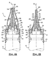
- FIGS. 4A and 4B differs from the embodiment previous in that the valve 11 is of the depression type.
- the tip of distribution 20 form two "ears" 26, 27 so as to allow actuation of the valve by an axial displacement of the nozzle 20 towards the container 2 (see Figure 4B).
- the profile of the cover is different from the profile of the cover of the preceding embodiment so that, when screwing the cover on the endpiece 20 ( Figure 4A), the cover 30 does not come into engagement with the ears of the tip 20, which engagement would be likely to cause a inadvertent actuation of the valve 11.
- the device 1 is also in all respects identical to that of the mode of previous realization.
Landscapes
- Chemical & Material Sciences (AREA)
- Dispersion Chemistry (AREA)
- Engineering & Computer Science (AREA)
- Mechanical Engineering (AREA)
- Closures For Containers (AREA)
- Containers And Packaging Bodies Having A Special Means To Remove Contents (AREA)
- Vending Machines For Individual Products (AREA)
- Containers And Plastic Fillers For Packaging (AREA)
Claims (14)
- Vorrichtung (1) zur Verpackung und zur Ausgabe eines insbesondere kosmetischen Produkts unter Druck, die einen das Produkt enthaltenden Behälter (2) aufweist, wobei über dem Behälter ein Ausgabeelement (11), insbesondere ein Ventil, und ein Ausgabekopf (10) zur Betätigung des Ausgabeelements und zur Ausgabe des Produkts über mindestens eine Ausgabeöffnung (22) sitzen, wobei der Ausgabekopf aufweist: a) einen Montage-Bundring (13), der fest mit dem Behälter verbunden ist; b) einen Ausgabe-Aufsatz (20), der einen Kanal (21) bildet, der an der Ausgabeöffnung mündet, wobei der Aufsatz (20) in der Lage ist, sich als Reaktion auf eine Betätigungssteuerung zu bewegen, um die Betätigung des Ausgabeelements (11) zu bewirken; und c) eine Kappe (30), die auf den Ausgabe-Aufsatz geschraubt ist und Mittel (33) aufweist, um in der festgeschraubten Stellung der Kappe die Betätigung des Ausgabeelements (11) zu verhindern, dadurch gekennzeichnet, dass der Aufsatz (20) bezüglich des Montage-Bundrings (13) in Drehung fest ist.
- Vorrichtung (1) nach Anspruch 1, dadurch gekennzeichnet, dass der Ausgabe-Aufsatz (20) ein Gewinde (31) aufweist, das in der Lage ist, mit einem entsprechenden Gewinde (32) der Kappe (30) zusammenzuwirken, wobei das Gewinde (31) auf einem Abschnitt des Aufsatzes ausgebildet ist, dessen Querschnitt größer ist als der Querschnitt eines freien Endes des Aufsatzes, wo die Ausgabeöffnung (22) mündet.
- Vorrichtung (1) nach Anspruch 2, dadurch gekennzeichnet, dass das Gewinde (31) des Aufsatzes (20) von der Ausgabeöffnung (22) durch mindestens einen Abschnitt mit einem Querschnitt getrennt ist, der progressiv in Richtung des Gewindes (31) und/oder um mindestens eine Stufe ansteigt.
- Vorrichtung (1) nach einem der Ansprüche 1 bis 3, dadurch gekennzeichnet, dass das Gewinde (32) der Kappe (30) auf der Innenfläche einer äußeren Seitenwand der Kappe (30) vorgesehen ist.
- Vorrichtung (1) nach einem der Ansprüche 1 bis 4, dadurch gekennzeichnet, dass der Ausgabe-Aufsatz (20) von einem Bauteil gebildet wird, das sich vom Montage-Bundring (13) unterscheidet.
- Vorrichtung (1) nach einem der Ansprüche 1 bis 5, dadurch gekennzeichnet, dass das Ausgabeelement aus einem Ventil (11) besteht, wobei das Produkt innerhalb des Behälters (2) unter Druck steht.
- Vorrichtung (1) nach Anspruch 6, dadurch gekennzeichnet, dass das Ventil (11) ein Kippventil ist, das als Reaktion auf einen Querdruck auf eine Längsachse (X) des Ventils betätigt werden kann.
- Vorrichtung (1) nach Anspruch 6, dadurch gekennzeichnet, dass das Ventil (11) ein Eindrückventil ist, das als Reaktion auf einen axial zum Ventil (11) gerichteten Druck betätigt werden kann.
- Vorrichtung (1) nach einem der Ansprüche 1 bis 8, dadurch gekennzeichnet, dass der Montage-Bundring (13) fest auf dem Behälter (2) befestigt ist, insbesondere durch klemmendes Einklinken.
- Vorrichtung (1) nach einem der Ansprüche 1 bis 9, dadurch gekennzeichnet, dass der Ausgabe-Aufsatz (20) bezüglich des Montage-Bundrings mittels einer oder mehrerer Rasten (23) in Drehung blockiert wird, die vom Montage-Bundring (13) bzw. dem Aufsatz (20) gebildet werden und in der Lage sind, sich in eine entsprechende Anzahl von Nuten (24) einzufügen, die vom Ausgabe-Aufsatz (20) bzw. dem Montage-Bundring (13) gebildet werden.
- Vorrichtung (1) nach einem der Ansprüche 1 bis 10, dadurch gekennzeichnet, dass die Mittel, die in der Lage sind, in der festgeschraubten Stellung der Kappe die Betätigung des Ausgabeelements zu verhindern, aus einem insbesondere ringförmigen Rand (33) der Kappe (30) bestehen, der in der festgeschraubten Stellung der Kappe (30) auf dem Ausgabe-Aufsatz mit dem Montage-Bundring (13) in Kontakt steht.
- Vorrichtung (1) nach einem der vorhergehenden Ansprüche, dadurch gekennzeichnet, dass die Kappe (30) so gestaltet ist, dass in ihrer auf den Aufsatz (20) geschraubten Stellung ein Abschnitt (34) der Kappe mit der Ausgabeöffnung (22) in Eingriff steht, um diese dicht zu verschließen.
- Vorrichtung (1) nach einem der vorhergehenden Ansprüche, dadurch gekennzeichnet, dass der Ausgabe-Aufsatz (20) ein Element (25) insbesondere in Form eines ringförmigen Kragens aufweist, das in Zusammenwirkung mit einem entsprechenden Abschnitt (16) des Bundrings (13) das Lösen des Ausgabe-Aufsatzes (20) vom Rest des Ausgabekopfes (10) verhindert.
- Verwendung einer Vorrichtung (1) nach einem der vorhergehenden Ansprüche zur Verpackung und zur Ausgabe eines kosmetisehen Produkts unter Druck, insbesondere eines Pflege-, Schmink-, Körperhygiene-, Haar- oder Hautsonnenschutzprodukts.
Applications Claiming Priority (2)
| Application Number | Priority Date | Filing Date | Title |
|---|---|---|---|
| FR0014253 | 2000-11-07 | ||
| FR0014253A FR2816290B1 (fr) | 2000-11-07 | 2000-11-07 | Dispositif de conditionnement et de distribution sous pression d'un produit |
Publications (2)
| Publication Number | Publication Date |
|---|---|
| EP1205403A1 EP1205403A1 (de) | 2002-05-15 |
| EP1205403B1 true EP1205403B1 (de) | 2005-05-18 |
Family
ID=8856142
Family Applications (1)
| Application Number | Title | Priority Date | Filing Date |
|---|---|---|---|
| EP01402589A Expired - Lifetime EP1205403B1 (de) | 2000-11-07 | 2001-10-08 | Einheit zur Aufbewahrung und Ausgabe eines unter Druck stehenden Produktes |
Country Status (8)
| Country | Link |
|---|---|
| US (1) | US6439440B1 (de) |
| EP (1) | EP1205403B1 (de) |
| JP (1) | JP2002238658A (de) |
| AT (1) | ATE295814T1 (de) |
| CA (1) | CA2360912C (de) |
| DE (1) | DE60110881T2 (de) |
| ES (1) | ES2242717T3 (de) |
| FR (1) | FR2816290B1 (de) |
Families Citing this family (26)
| Publication number | Priority date | Publication date | Assignee | Title |
|---|---|---|---|---|
| FR2828871B1 (fr) * | 2001-08-22 | 2003-12-19 | Oreal | Dispositif de conditionnement et de distribution sous pression d'un produit |
| DE20303260U1 (de) * | 2003-02-28 | 2004-07-08 | Lindal Ventil Gmbh | Verschluß für ein Ventil mit einem innenliegenden Ventilsitz |
| USD535721S1 (en) * | 2005-03-17 | 2007-01-23 | Plaspak Pty Limited | Nozzle |
| US7762427B2 (en) * | 2005-06-10 | 2010-07-27 | Kranson Industries, Inc. | Pump dispensing mechanism |
| JP2009502674A (ja) * | 2005-07-29 | 2009-01-29 | シュ パッケージング プロダクツ リミテッド | 弁を備える液体および発射気体用の容器 |
| US7934667B2 (en) * | 2005-12-08 | 2011-05-03 | L'oreal | Diffuser and device for packaging and dispensing a foaming product |
| WO2008012191A1 (en) * | 2006-07-25 | 2008-01-31 | L'oreal | Assembly for packaging and dispensing a product, in particular a cosmetic product |
| FR2904295B1 (fr) * | 2006-07-25 | 2008-09-12 | Oreal | Ensemble de conditionnement et de distribution d'un produit, notamment cosmetique |
| US8286838B2 (en) * | 2007-03-30 | 2012-10-16 | LF Beauty | Leak proof fragrance bottle |
| US8387827B2 (en) | 2008-03-24 | 2013-03-05 | S.C. Johnson & Son, Inc. | Volatile material dispenser |
| WO2011133779A2 (en) * | 2010-04-21 | 2011-10-27 | Tfb Consultants Ltd | Liquid decanting method and apparatus |
| US12030023B2 (en) * | 2010-04-21 | 2024-07-09 | Winepro2, Ltd | Gas dispensing method and apparatus |
| KR200466740Y1 (ko) | 2011-02-24 | 2013-05-09 | 이후만 | 염모제 용기 |
| US9060654B2 (en) | 2011-08-15 | 2015-06-23 | Gojo Industries, Inc. | Dispenser with multi-directional pushbar |
| MX2014011627A (es) * | 2012-04-27 | 2014-10-17 | Procter & Gamble | Unidad aplicadora para aplicar una composicion. |
| USD696417S1 (en) * | 2012-06-11 | 2013-12-24 | Aptar France Sas | Fluid dispenser |
| USD696789S1 (en) * | 2012-06-11 | 2013-12-31 | Aptar France Sas | Fluid dispenser |
| USD696788S1 (en) * | 2012-06-11 | 2013-12-31 | Aptar France Sas | Fluid dispenser |
| USD695907S1 (en) * | 2012-06-11 | 2013-12-17 | Aptar France Sas | Fluid dispenser |
| DE202012102354U1 (de) | 2012-06-26 | 2012-07-18 | Tremco Illbruck Productie B.V. | System aus einer Kappe zur Befestigung auf einer Schaumdose und aus einem Spender |
| EP2796206B1 (de) * | 2013-04-26 | 2016-12-21 | Aptar Radolfzell GmbH | Austragkopf für einen Behälter und Verfahren zur Befestigung eines Austragkopfs an einem Behälter |
| CN105188850A (zh) | 2013-05-16 | 2015-12-23 | 宝洁公司 | 毛发增稠组合物及使用方法 |
| US10285926B2 (en) | 2015-06-29 | 2019-05-14 | The Procter & Gamble Company | Superabsorbent polymers and starch powders for use in skin care compositions |
| EP3544908B1 (de) * | 2016-11-28 | 2021-07-07 | L'Oreal | Vorrichtung zur verpackung und ausgabe eines produkts mit einem beweglichen kolben |
| USD912713S1 (en) * | 2019-10-11 | 2021-03-09 | Kevin Francis Moran | Oil filter removal device |
| USD912714S1 (en) * | 2019-10-11 | 2021-03-09 | Kevin Francis Moran | Oil filter removal device |
Family Cites Families (8)
| Publication number | Priority date | Publication date | Assignee | Title |
|---|---|---|---|---|
| US2767888A (en) * | 1954-03-17 | 1956-10-23 | Dev Res Inc | Shields and caps for containers |
| US3233788A (en) * | 1963-04-23 | 1966-02-08 | Glen Gardner Corp | Snap-on cover for pressure dispensers |
| US3901410A (en) * | 1974-07-19 | 1975-08-26 | Robert S Schultz | Captive tip-seal valve |
| FR2570000A1 (fr) * | 1984-09-12 | 1986-03-14 | Valve Precision Sarl | Dispositif de diffusion en matiere plastique pour recipient sous pression |
| US4944429A (en) * | 1987-08-28 | 1990-07-31 | Schering Corporation | Manually-operable spray dispenser with locking mechanism |
| FR2626254B1 (fr) * | 1988-01-27 | 1990-07-06 | Valois Sa | Poussoir-etui avec systeme de garantie |
| FR2635085B3 (fr) * | 1988-08-08 | 1990-11-02 | Sofab | Distributeur a embout inviolable |
| US5722568A (en) * | 1996-09-13 | 1998-03-03 | Summit Packaging Systems, Inc. | Tamper-evident aerosol cap |
-
2000
- 2000-11-07 FR FR0014253A patent/FR2816290B1/fr not_active Expired - Fee Related
-
2001
- 2001-10-08 EP EP01402589A patent/EP1205403B1/de not_active Expired - Lifetime
- 2001-10-08 DE DE60110881T patent/DE60110881T2/de not_active Expired - Lifetime
- 2001-10-08 AT AT01402589T patent/ATE295814T1/de not_active IP Right Cessation
- 2001-10-08 ES ES01402589T patent/ES2242717T3/es not_active Expired - Lifetime
- 2001-10-31 CA CA002360912A patent/CA2360912C/fr not_active Expired - Fee Related
- 2001-11-07 US US09/986,028 patent/US6439440B1/en not_active Expired - Lifetime
- 2001-11-07 JP JP2001342598A patent/JP2002238658A/ja not_active Ceased
Also Published As
| Publication number | Publication date |
|---|---|
| ATE295814T1 (de) | 2005-06-15 |
| DE60110881D1 (de) | 2005-06-23 |
| EP1205403A1 (de) | 2002-05-15 |
| FR2816290A1 (fr) | 2002-05-10 |
| US20020056733A1 (en) | 2002-05-16 |
| FR2816290B1 (fr) | 2003-01-10 |
| ES2242717T3 (es) | 2005-11-16 |
| DE60110881T2 (de) | 2006-04-27 |
| JP2002238658A (ja) | 2002-08-27 |
| CA2360912A1 (fr) | 2002-05-07 |
| US6439440B1 (en) | 2002-08-27 |
| CA2360912C (fr) | 2005-12-06 |
Similar Documents
| Publication | Publication Date | Title |
|---|---|---|
| EP1205403B1 (de) | Einheit zur Aufbewahrung und Ausgabe eines unter Druck stehenden Produktes | |
| CA2368052C (fr) | Dispositif pressurise equipe d'une valve a basculement | |
| EP1288142B1 (de) | Einheit zur Aufbewahrung und Ausgabe eines unter Druck stehenden Produktes | |
| BE1004397A3 (fr) | Dispositif permettant le conditionnement d'un produit et sa distribution par la manoeuvre d'un bouton-poussoir associe a un applicateur tubulaire. | |
| EP0899213B1 (de) | Mit einer Pumpe versehene Verpackungseinheit für ein flüssiges oder halbflüssiges Produktes | |
| EP0737628B1 (de) | Vorrichtung zum Aufbewahren und Ausgeben eines flüssigen oder pastösen Produktes | |
| EP0945368A1 (de) | Auftragskopf zur Abgabe von einem Produkt, insbesondere Haarpflegeprodukt, und Verpackungseinheit mit einem solchen Kopf | |
| EP0765822B1 (de) | Vorrichtung mit Sicherheitsventil zur Ausgabe von flüssigen Produkten unter Druck | |
| EP1052023A1 (de) | Augsgabekopf und damit ausgerüsteter Behälter | |
| EP1291293A1 (de) | Ventil mit variablem Durchfluss und Behälter mit einem solchen Ventil | |
| EP0874761B1 (de) | Ausgiesser für flüssige oder pastöse produkte | |
| EP0939039A1 (de) | Ausgabekopf zur Ausgabe eines Stoffs sowie eine mit einem solchen Ausgabekopf versehene Ausgabevorrichtung | |
| EP1671705B1 (de) | Mit einer Pumpe ausgestatteter Kunststoffspender | |
| EP0960829B1 (de) | Ventil sowie Aufbewahrungs- und Ausgabevorrichtung mit einem solchen Ventil | |
| FR2768409A1 (fr) | Ensemble de conditionnement et de distribution d'un produit liquide ou semi liquide | |
| EP0850851B1 (de) | Ventil für die Abgabe von unter Druck stehenden Fluiden | |
| EP2178415A2 (de) | Vorrichtung für ein kosmetikprodukt mit einem tank und einem applikator | |
| FR2814727A1 (fr) | Valve destinee a equiper un dispositif pour la distribution sous pression d'un produit, et dispositif ainsi equipe | |
| FR2760227A1 (fr) | Tete de distribution et distributeur equipe d'une telle tete | |
| EP1535860A1 (de) | Kippventil mit variablem Durchfluss | |
| CA2297765C (fr) | Valve pour dispositif des fluides sous pression | |
| FR2814726A1 (fr) | Valve destinee a equiper un dispositif pour la distribution sous pression d'un produit, et dispositif ainsi equipe | |
| WO2015028759A1 (fr) | Dispositif de conditionnement et de distribution d'un produit cosmetique | |
| FR2904296A1 (fr) | Dispositif de conditionnement et de distribution d'un produit sous pression |
Legal Events
| Date | Code | Title | Description |
|---|---|---|---|
| PUAI | Public reference made under article 153(3) epc to a published international application that has entered the european phase |
Free format text: ORIGINAL CODE: 0009012 |
|
| AK | Designated contracting states |
Kind code of ref document: A1 Designated state(s): AT BE CH CY DE DK ES FI FR GB GR IE IT LI LU MC NL PT SE TR |
|
| AX | Request for extension of the european patent |
Free format text: AL;LT;LV;MK;RO;SI |
|
| 17P | Request for examination filed |
Effective date: 20021115 |
|
| AKX | Designation fees paid |
Designated state(s): AT BE CH CY DE DK ES FI FR GB GR IE IT LI LU MC NL PT SE TR |
|
| GRAP | Despatch of communication of intention to grant a patent |
Free format text: ORIGINAL CODE: EPIDOSNIGR1 |
|
| GRAS | Grant fee paid |
Free format text: ORIGINAL CODE: EPIDOSNIGR3 |
|
| GRAA | (expected) grant |
Free format text: ORIGINAL CODE: 0009210 |
|
| AK | Designated contracting states |
Kind code of ref document: B1 Designated state(s): AT BE CH CY DE DK ES FI FR GB GR IE IT LI LU MC NL PT SE TR |
|
| PG25 | Lapsed in a contracting state [announced via postgrant information from national office to epo] |
Ref country code: IE Free format text: LAPSE BECAUSE OF FAILURE TO SUBMIT A TRANSLATION OF THE DESCRIPTION OR TO PAY THE FEE WITHIN THE PRESCRIBED TIME-LIMIT Effective date: 20050518 Ref country code: FI Free format text: LAPSE BECAUSE OF FAILURE TO SUBMIT A TRANSLATION OF THE DESCRIPTION OR TO PAY THE FEE WITHIN THE PRESCRIBED TIME-LIMIT Effective date: 20050518 Ref country code: NL Free format text: LAPSE BECAUSE OF FAILURE TO SUBMIT A TRANSLATION OF THE DESCRIPTION OR TO PAY THE FEE WITHIN THE PRESCRIBED TIME-LIMIT Effective date: 20050518 Ref country code: AT Free format text: LAPSE BECAUSE OF FAILURE TO SUBMIT A TRANSLATION OF THE DESCRIPTION OR TO PAY THE FEE WITHIN THE PRESCRIBED TIME-LIMIT Effective date: 20050518 Ref country code: TR Free format text: LAPSE BECAUSE OF FAILURE TO SUBMIT A TRANSLATION OF THE DESCRIPTION OR TO PAY THE FEE WITHIN THE PRESCRIBED TIME-LIMIT Effective date: 20050518 |
|
| REG | Reference to a national code |
Ref country code: GB Ref legal event code: FG4D Free format text: NOT ENGLISH |
|
| REG | Reference to a national code |
Ref country code: CH Ref legal event code: EP |
|
| REG | Reference to a national code |
Ref country code: IE Ref legal event code: FG4D Free format text: LANGUAGE OF EP DOCUMENT: FRENCH |
|
| REF | Corresponds to: |
Ref document number: 60110881 Country of ref document: DE Date of ref document: 20050623 Kind code of ref document: P |
|
| PG25 | Lapsed in a contracting state [announced via postgrant information from national office to epo] |
Ref country code: GR Free format text: LAPSE BECAUSE OF FAILURE TO SUBMIT A TRANSLATION OF THE DESCRIPTION OR TO PAY THE FEE WITHIN THE PRESCRIBED TIME-LIMIT Effective date: 20050818 Ref country code: DK Free format text: LAPSE BECAUSE OF FAILURE TO SUBMIT A TRANSLATION OF THE DESCRIPTION OR TO PAY THE FEE WITHIN THE PRESCRIBED TIME-LIMIT Effective date: 20050818 Ref country code: SE Free format text: LAPSE BECAUSE OF FAILURE TO SUBMIT A TRANSLATION OF THE DESCRIPTION OR TO PAY THE FEE WITHIN THE PRESCRIBED TIME-LIMIT Effective date: 20050818 |
|
| GBT | Gb: translation of ep patent filed (gb section 77(6)(a)/1977) |
Effective date: 20050819 |
|
| PG25 | Lapsed in a contracting state [announced via postgrant information from national office to epo] |
Ref country code: CY Free format text: LAPSE BECAUSE OF FAILURE TO SUBMIT A TRANSLATION OF THE DESCRIPTION OR TO PAY THE FEE WITHIN THE PRESCRIBED TIME-LIMIT Effective date: 20051008 |
|
| PG25 | Lapsed in a contracting state [announced via postgrant information from national office to epo] |
Ref country code: PT Free format text: LAPSE BECAUSE OF FAILURE TO SUBMIT A TRANSLATION OF THE DESCRIPTION OR TO PAY THE FEE WITHIN THE PRESCRIBED TIME-LIMIT Effective date: 20051024 |
|
| PG25 | Lapsed in a contracting state [announced via postgrant information from national office to epo] |
Ref country code: LU Free format text: LAPSE BECAUSE OF NON-PAYMENT OF DUE FEES Effective date: 20051031 Ref country code: MC Free format text: LAPSE BECAUSE OF NON-PAYMENT OF DUE FEES Effective date: 20051031 Ref country code: LI Free format text: LAPSE BECAUSE OF NON-PAYMENT OF DUE FEES Effective date: 20051031 Ref country code: CH Free format text: LAPSE BECAUSE OF NON-PAYMENT OF DUE FEES Effective date: 20051031 Ref country code: BE Free format text: LAPSE BECAUSE OF NON-PAYMENT OF DUE FEES Effective date: 20051031 |
|
| REG | Reference to a national code |
Ref country code: ES Ref legal event code: FG2A Ref document number: 2242717 Country of ref document: ES Kind code of ref document: T3 |
|
| NLV1 | Nl: lapsed or annulled due to failure to fulfill the requirements of art. 29p and 29m of the patents act | ||
| REG | Reference to a national code |
Ref country code: IE Ref legal event code: FD4D |
|
| PLBE | No opposition filed within time limit |
Free format text: ORIGINAL CODE: 0009261 |
|
| STAA | Information on the status of an ep patent application or granted ep patent |
Free format text: STATUS: NO OPPOSITION FILED WITHIN TIME LIMIT |
|
| 26N | No opposition filed |
Effective date: 20060221 |
|
| REG | Reference to a national code |
Ref country code: CH Ref legal event code: PL |
|
| BERE | Be: lapsed |
Owner name: L'OREAL Effective date: 20051031 |
|
| REG | Reference to a national code |
Ref country code: FR Ref legal event code: PLFP Year of fee payment: 15 |
|
| REG | Reference to a national code |
Ref country code: FR Ref legal event code: PLFP Year of fee payment: 16 |
|
| REG | Reference to a national code |
Ref country code: FR Ref legal event code: PLFP Year of fee payment: 17 |
|
| REG | Reference to a national code |
Ref country code: FR Ref legal event code: PLFP Year of fee payment: 18 |
|
| PGFP | Annual fee paid to national office [announced via postgrant information from national office to epo] |
Ref country code: FR Payment date: 20190913 Year of fee payment: 19 |
|
| PGFP | Annual fee paid to national office [announced via postgrant information from national office to epo] |
Ref country code: DE Payment date: 20190924 Year of fee payment: 19 |
|
| PGFP | Annual fee paid to national office [announced via postgrant information from national office to epo] |
Ref country code: ES Payment date: 20191104 Year of fee payment: 19 Ref country code: IT Payment date: 20191009 Year of fee payment: 19 |
|
| PGFP | Annual fee paid to national office [announced via postgrant information from national office to epo] |
Ref country code: GB Payment date: 20191003 Year of fee payment: 19 |
|
| REG | Reference to a national code |
Ref country code: DE Ref legal event code: R119 Ref document number: 60110881 Country of ref document: DE |
|
| GBPC | Gb: european patent ceased through non-payment of renewal fee |
Effective date: 20201008 |
|
| PG25 | Lapsed in a contracting state [announced via postgrant information from national office to epo] |
Ref country code: FR Free format text: LAPSE BECAUSE OF NON-PAYMENT OF DUE FEES Effective date: 20201031 Ref country code: DE Free format text: LAPSE BECAUSE OF NON-PAYMENT OF DUE FEES Effective date: 20210501 |
|
| PG25 | Lapsed in a contracting state [announced via postgrant information from national office to epo] |
Ref country code: GB Free format text: LAPSE BECAUSE OF NON-PAYMENT OF DUE FEES Effective date: 20201008 |
|
| PG25 | Lapsed in a contracting state [announced via postgrant information from national office to epo] |
Ref country code: IT Free format text: LAPSE BECAUSE OF NON-PAYMENT OF DUE FEES Effective date: 20201008 |
|
| REG | Reference to a national code |
Ref country code: ES Ref legal event code: FD2A Effective date: 20220127 |
|
| PG25 | Lapsed in a contracting state [announced via postgrant information from national office to epo] |
Ref country code: ES Free format text: LAPSE BECAUSE OF NON-PAYMENT OF DUE FEES Effective date: 20201009 |