EP0737636A1 - Vorrichtung zur stückweisen Abgabe von Broschüren zu einer Aufnahmestation und Abgabeverfahren ausgeführt durch die genannte Vorrichtung - Google Patents
Vorrichtung zur stückweisen Abgabe von Broschüren zu einer Aufnahmestation und Abgabeverfahren ausgeführt durch die genannte Vorrichtung Download PDFInfo
- Publication number
- EP0737636A1 EP0737636A1 EP95830130A EP95830130A EP0737636A1 EP 0737636 A1 EP0737636 A1 EP 0737636A1 EP 95830130 A EP95830130 A EP 95830130A EP 95830130 A EP95830130 A EP 95830130A EP 0737636 A1 EP0737636 A1 EP 0737636A1
- Authority
- EP
- European Patent Office
- Prior art keywords
- brochure
- brochures
- belt conveyor
- locating member
- back edge
- Prior art date
- Legal status (The legal status is an assumption and is not a legal conclusion. Google has not performed a legal analysis and makes no representation as to the accuracy of the status listed.)
- Granted
Links
- 238000000034 method Methods 0.000 title claims description 17
- 230000000694 effects Effects 0.000 title description 3
- 238000005192 partition Methods 0.000 claims abstract description 11
- 230000009471 action Effects 0.000 claims description 24
- 238000000605 extraction Methods 0.000 claims description 20
- 230000013011 mating Effects 0.000 claims description 3
- 238000011144 upstream manufacturing Methods 0.000 claims description 3
- 230000006355 external stress Effects 0.000 claims 3
- 238000001514 detection method Methods 0.000 claims 1
- 230000000284 resting effect Effects 0.000 abstract 1
- 238000004806 packaging method and process Methods 0.000 description 12
- 230000008901 benefit Effects 0.000 description 4
- 238000006073 displacement reaction Methods 0.000 description 2
- 230000002093 peripheral effect Effects 0.000 description 2
- 238000009825 accumulation Methods 0.000 description 1
- 238000010276 construction Methods 0.000 description 1
- 238000003780 insertion Methods 0.000 description 1
- 230000037431 insertion Effects 0.000 description 1
- 230000007257 malfunction Effects 0.000 description 1
- 238000012986 modification Methods 0.000 description 1
- 230000004048 modification Effects 0.000 description 1
- 230000009467 reduction Effects 0.000 description 1
- 230000000717 retained effect Effects 0.000 description 1
Images


Classifications
-
- B—PERFORMING OPERATIONS; TRANSPORTING
- B65—CONVEYING; PACKING; STORING; HANDLING THIN OR FILAMENTARY MATERIAL
- B65H—HANDLING THIN OR FILAMENTARY MATERIAL, e.g. SHEETS, WEBS, CABLES
- B65H5/00—Feeding articles separated from piles; Feeding articles to machines
- B65H5/36—Article guides or smoothers, e.g. movable in operation
-
- B—PERFORMING OPERATIONS; TRANSPORTING
- B65—CONVEYING; PACKING; STORING; HANDLING THIN OR FILAMENTARY MATERIAL
- B65H—HANDLING THIN OR FILAMENTARY MATERIAL, e.g. SHEETS, WEBS, CABLES
- B65H9/00—Registering, e.g. orientating, articles; Devices therefor
- B65H9/08—Holding devices, e.g. finger, needle, suction, for retaining articles in registered position
Definitions
- the present invention relates to a unit for individually feeding brochures to a pick-up station, of the type comprising a belt conveyor terminating at said pick-up station.
- the present invention also relates to a method of feeding brochures put into practice by said unit.
- the feeding unit is designed to be associated with a machine for packaging compact dics into respective cases in order to supply the machine with booklets, covers or leaflets (in the following referred to as brochures) to be inserted into the cases themselves upon the action of mechanical handling devices provided in the packaging machine.
- the operator when it is necessary, lays down a number of brochures stacked on top of each other at the beginning of the longitudinal extension of the belt conveyor, distributing them in a direction towards the pick-up station so that, when the distribution is completed, each brochure projects towards the pick-up station with respect to the net one disposed immediately below.
- the belt conveyor is then operated to make the brochures progress towards the pick-up station, until said station is reached by the first one of said brochures.
- the belt conveyor is then stopped upon command of photoelectric cells or similar sensor means arranged in the pick-up station, to enable picking up of the first brochure by said handling device; afterwards the belt conveyor will be operated again so as to position the subsequent brochure in the pick-up station.
- the amount of the brochures to be disposed on the belt is closely connected with the longitudinal extension of the belt conveyor. It is therefore difficult to reach a sufficiently self-contained operation, above all in the packaging machines of small sizes, where the belt conveyor length is necessarily restricted. In addition, a correct distribution of the brochures on the belt always requires a certain skill by the operator.
- a unit for individually feeding brochures to a pick-up station characterized in that it comprises: a feeding magazine arranged to receive a plurality of brochures disposed consecutively on top of each other to form a stack, at least one of said brochures, disposed in a lowermost position in said stack, acting in abutment on the belt conveyor to be withdrawn upon the action of the conveyor itself, through an outlet side of the feeding magazine, at least one locating member supported above the belt conveyor and defining therewith a gauged passage clearance "Z" of greater width than the nominal thickness "h” of each brochure, said locating member being arranged so as to interfere with one back edge of the brochure to stop progress of same on the belt conveyor; presser means operatively associated with said locating member and arranged to exert a thrust action on the back edge of said brochure so as to elastically deform it from a free condition in which the upper surface of the brochure at the back edge lies at a slightly higher level than
- this feeding unit operates following a method of individually feeding brochures to a pick-up station, characterized in that it comprises the steps of: arranging a plurality of brochures disposed consecutively on top of each other to form a stack inside a feeding magazine, at least one of said brochures located in a lowermost position in the stack acting in abutment on a belt conveyor; operating the belt conveyor for withdrawing at least said lowermost brochure through an outlet side of the feeding magazine; stopping movement of the brochure against a locating member supported above the belt conveyor and defining therewith a gauged passage clearance "Z" of greater width than the nominal thickness "h” of each brochure; exerting a thrust action on the back edge of said brochure so as to elastically deform it from a free condition in which the upper surface of the brochure at the back edge lies at a slightly higher level than the lower end of the locating member, to an elastic-yielding condition in which said upper surface is brought under the lower end of the locating member, so that the brochure can be moved by the belt
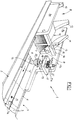
- a unit for individually feeding brochures onto a belt conveyor according to the invention has been generally identified by reference numeral 1.
- the feeding unit 1 comprises a belt conveyor 2 that, in the example shown, is conventionally associated with a machine for automatically packaging compact discs, in order to individually transfer brochures 4 to a pick-up station 5, at which station each brochure 4 will be picked up by a handling device belonging to the packaging machine itself.
- the belt conveyor 2 essentially comprises one or more parallel endless belts 3 usually moved along a slide surface 3a according to a feed direction shown by arrow "A".
- the unit 1 is arranged so as to operate on brochures 4 consisting of booklets.
- each brochure 4 consists of two or more pages 6 disposed upon each other in matino relationship and defined by at least one sheet folded along a back edge 7 oriented in the feed direction "A". It should be noted that, due to the residual elasticity in the material forming said sheet, folding produced at the back edge 7 causes the pages 6, at said back edge, not to be perfectly coupled against each other, but to be slightly spaced apart.
- the height "H" detectable close to said back edge is greater than the nominal thickness "h", corresponding to the sum of the page thicknesses and detectable on said pages 6 themselves when they perfectly mate.
- the feeding unit 1 is provided with a feeding magazine B mounted on the belt conveyor 2 and comprising at least two housing side walls 8a between which an outlet side 9 is defined, which is oriented in the feed direction "A" of the conveyor itself.
- the magazine 8 houses a plurality of brochures 4 having the respective back edges 7 facing the outlet side 9 and placed consecutively on top of each other to form a stack generally denoted by 10.
- At least the lowermost brochure 4 in the stack 10 directly acts in abutment on the endless belts 3 of the belt conveyor 2 and therefore can be withdrawm from the magazine through the outlet side 9 following operation of the belt conveyor.
- one or more guide elements 11 are fastened to the inner surfaces of the housing walls 8a of the magazine 8 and act on the upper part of the opposite side edges of the brochures 4 so as to give the stack 10 a curvilinear and/or substantially inclined extension, in order that each brochure 4 may slightly project towards the outlet side 9 relative to the brochure 4 placed immediately upon it.
- the action of the guide element or elements 11 may be assisted to advantage by one or more auxiliary guide elements 12 adapted to act on the lower surf aces of the brochures' side edges.
- At least one partition element 13 is operatively supported at the outlet side 9 and it essentially consists of a rod passing through and removably fastened, according to a substantially vertical axis, to a horizontal support bar 14 secured between the housing walls 8a of the feeding magazine 8.
- positioning means consisting for example of a headless screw 15 operatively engaged through the support bar 14 and by which it is possible to modify the axial positioning of the rod so as to suitably adjust the width of an outlet port "Y" defined between the lower end of the partition rod 13 and the belt conveyor surface, and more particulary, the endless belts 3 belonging to said belt conveyor 2.
- the width adjustment of the outlet port "Y” aims at causing that only a predetermined number of brochures 4 should simultaneously pass through the outlet side 9.
- the width of this outlet port "Y” is preferably adjusted according to an amount substantially corresponding to the height "H” detectable at the back edge 7 of each brochure 4 in said free condition, so as to hinder the simultaneous passage of more than one brochure under the partition rod 13.
- At least one locating member 16 Downstream of the feeding magazine 8 and preferable to a distance "D" lower than the longitudinal dimension "L” of each brochure 4, at least one locating member 16 operates, being supported above the belt conveyor 2 and arranged to interfere with the back edge 7 of the brochure 4 emerging from the feeding magazine 8, to stop progress of same along the belt conveyor 2. In other words, when the back edge 7 encounters the locating member 16, the corresponding brochure 4 will be stopped and, since operation of tile belt conveyor 2 goes on, the endless belts 3 will be caused to slide under the brochure itself.
- the locating member 16 substantially comprises a rod-like element operatively connected, according to a substantially vertical axis, to a support bracket 17 integral with the belt conveyor 2.
- the support bracket 17 is rigidly linked to an extension 17a of one of the housing walls 8a of the feeding magazine 8.
- this adjusting means consists of a threaded portion 16a disposed on the rod-like element forming said locator 16 and operating in engagement through the support bracket 17.
- the axial positioning of the rod-like element 16 is such adjusted that, between the lower end 16b of said element and the belt conveyor 2 (and more particularly the work surface 3b of one of the endless belts 3) a gauged passage clearance "Z" is created the width of which is greater than the nominal thickness "h” and preferably included between the value and twice the value of said thickness.
- the width of the gauged clearance "Z" is to be smaller than the height "H" that is found close to the back edge 7 of each brochure 4 in a free condition, to ensure stopping of same by the locating member 16.
- a locking nut 18 operatively fitted on the threaded portion 16a enables locking of the locating member.
- presser means 19 selectively operable to exert a thrust action on the back edge 7 of the brochure 4 at a standstill against the locating member itself.
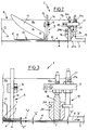
- This presser means 19 preferably comprises at least one pusher element 20 slidably guided along the rod-like element 16 and selectively movable from a rest position in which as shown in Figs 1 and 2, it is raised from the brochure 4, to an operating condition in which, as shown in Fig. 3, it acts in thrust relation on the brochure back edge 7.
- the thrust action exerted by it on the back edge 7 of the brochure 4 causes the mutual approaching of the pages 6 in the vicinity of the back edge, so that the brochure 4 is brought to a yielding condition in which the detectable height at the back edge 7 is substantially identical with the nominal thickness "h", and in any case lower than the dimension of the gauged passage clearance "Z".
- the upper surface of the brochure 4 is brought below the lower end 16b of the locating member 16 and the brochure itself is allowed to pass under the locating member 16, by effect of the dragging action exerted by the belt conveyor 2.
- the pusher element 20 has a cylindrical configuration with a tapered lower end, so that it acts on the brochure 4 by its end portion 20a of reduced size, which will ensure concentration of the thrust force on the back edge 7.
- the pusher element 20 is at least partly made of a material that in contact with the brochure 4, gives rise to a friction coefficient lower than that generated by the belt conveyor, and more particularly the endless belts 3 belonging to said belt conveyor.
- Movement of the pusher element 20 takes place upon command of at least one fluid-operated actuator or another type of actuator 21 that, in a preferential solution, is activated upon command of at least one photoelectric cell 22 or equivalent sensor means arranged in the pick-up station 5, so as to enable transferring of a new brochure 4 to the pick-up station when picking-up of the brochure previously disposed therein has occurred by said handling device associated with the packaging machine.
- the fluid-operated actuator 21 is disposed in side-by-side relation with the locating member 16 and acts on the pusher element 20 at an annular groove 20b formed peripherally in said pusher element 20.
- Actuator 21 also has a threaded portion 21a which is operatively engaged through the support bracket 17. Therefore the axial positioning of the actuator 21 can be modified by rotating it so as to adjust positioning of the pusher element 20 in the operating condition.
- the adjustment takes place in such a manner that, in the operating condition, the pusher element 20 is stopped with its work portion 20a substantially flush with the lower end of the locating member 16, so as to prevent too much thrust force from being applied to the brochure 4.
- the pusher element 20 is capable of performing its function in an efficient manner also in the case in which two or more superposed brochures 4 should stop against the locating member 16 simultaneously. In fact, even if the pusher element 20 stops its stroke in its operating condition against the uppermost brochure 4, its thrust action will be in any case transmitted to the back edge 7 of the brochure 4 disposed on, and in direct contact with the belt conveyor 2, which brochure will be consequently lead to the compacting condition.
- Figs. 4 and 6 The embodiment therein shown is adapted to carry out feeding of brochures 4 both in the form of a booklet and in the form of a cover or individual leaflet.
- levelling means 23 to be associated with the belt conveyor 2, which levelling means is arranged close to the locating member 16 to keep the back-edge 7 of the brochure 4 slightly raised relative to the lower end 16b of the locating member itself.
- this levelling means 23 the brochure 4 emerging from the feeding magazine 8 is conveniently supported by the endless belts 3 which exhibit the respective work surfaces 3b at a slightly higher level than said slide surface 3a.
- At least one dragging roller 24 is also provided and it is operatively disposed between the endless belts, according to an axis perpendicular to the feed direction "A".
- the roller 24 at its opposite ends has terminal portions 24b acting on the belts 3 and in contact relationship therewith so as to cause the roller to be driven in rotation following operation of the belt conveyor 2.
- terminal portions 24b acting on the belts 3 and in contact relationship therewith so as to cause the roller to be driven in rotation following operation of the belt conveyor 2.
- at least one pressure roller 25 may be arranged so as to ensure engagement of the return stretches with the dragging roller 24 according to a wrapping arc sufficient to ensure an efficient driving in rotation of said roller.
- the dragging roller 24 is provided with an operating surface 24a arranged to act on the pusher element 20 and in contrast relationship therewith so as to facilitate dragging along of the brochure 4 when the latter is brought to the yielding condition upon the action of the pusher element itself.
- the operating surface 24a of the dragging roller 24 slightly projects on the upper side relative to the slide surface 3a, so as to assist or take the place of the endless belts 3 when performing their functions of levelling means 23, that is in arranging the back edge 7 of the brochure 4 slightly raised relative to the lower end 16b of the locating member 16.
- the brochure 4 (either in the form of an individual leaflet, or in the form of a cover or a booklet) coming from the feeding magazine 8 stops against the locating member 16, with its back edge 7 that, in the middle portion of its extension, is slightly raised from the underlying surface of the dragging roller 24.
- the photoelectric cell 22 causes the fluid-operated actuator 21 to intervene, the displacement of the pusher element 20 to the operating condition elastically deforms the back edge 7, leading the upper surface of the brochure 4 under the lower end 16b of the locating member 16.
- the brochure 4 Due to the effect of the endless belts 3 and dragging roller 24, the brochure 4 has therefore the possibility of being dragged along through the passage clearance "Z" that in this case is defined between the lower end 16b of the locating member 16 and the operating surface 24a of the dragging roller itself.
- an auxiliary feeder 26 may be associated to advantage with the unit 1 and it is intended to periodically supply the feeding magazine 8 with a new stack 10 of brochures 4.
- This auxiliary feeder 26 comprises at least one extraction wheel 27 operatively disposed upstream of the feeding magazine 8 and operable in rotation according to a horizontal axis perpendicular to the feed direction "A".
- the extraction wheel 27 is formed to advantage of one or more diametrical expansions formed on respective idler pulleys 27a coaxial with each other, usually arranged at the end of the belt conveyor 2 to conveniently support and guide the endless belts 3. Concurrently with operation of the belt conveyor 2, dragging induced on the idler pulleys 27a by the endless belts 3 therefore causes driving in rotation of the extraction wheel 24 at a peripheral speed greater than the movement speed of the belts themselves.
- a store 28 of brochures 4 stacked on top of each other and contained in a brochure holder acting as a supply receptacle 29 is arranged on the extraction wheel 27, which brochure holder extends in a substantially vertical direction, slightly sloping in a direction opposite to the feed direction "A".
- the brochure holder 29 which advantageously may consist of a box-shaped casing of the type usually used for transportation of the brochures 4, has an open side at the lower part thereof through which the extraction wheel 27 comes into contact with the lowermost one of the brochures 4.
- Shutoff means 30 is provided to disable the dragging action of the extraction wheel 27 when a given number of brochures 4 is present in the feeding magazine 8 and to restore said dragging action when the magazine is depleted of said brochures or the number of the latter has gone under a preset value.
- Said shutoff means 30 preferably is comprised of at least one lifting lever 31 interposed between the idler pulleys 27a and oscillatably engaged on a support axis 27b rotatably carrying said pulleys.
- An air cylinder 32 or similar means acts on the lifting lever 31 to selectively move it between a rest position, in which it has its work portion 31a spaced apart from the brochures 4 housed in the brochure holder 29, and an operating position in which said work portion acts on the lowermost brochure 4 in said store 28 to keep it slightly raised from the extraction wheel 27, so that said wheel can rotate freely without involving feeding of any brochures to the magazine 8.
- the air cylinder 32 is interlocked to a first and a second photoelectric cells 33a, 33b or equivalent drive means, associated with the feeding magazine 8 to operate moving of the lifting lever 31 to the rest or work position respectively, when the stack 10 height goes above or below a preset value.
- the auxiliary feeder 26 or, in the absence of said feeder, an operator assigned to assist operation of the packaging machine, supplies the feeding magazine 8 with a stack 10 of brochures 4, when required.
- the stack 10 is given a substantially inclined or stepped configuration, each brochure 4 projecting by its back side 7 towards the outlet side 9 of the magazine 8 relative to the immediately overlying brochure 4.
- the lowermost one of said brochures 4 in the stack 10 acts in abutment on the belt conveyor 2 and more particulary on the endless belts 3 belonging to said conveyor so that it is ready to be extracted through the outlet side 9 following operation of the conveyor itself. While one brochure 4 is being extracted from the magazine 8, the brochures disposed on top of it are conveniently retained in the magazine by the partition element 13.
- the brochure itself is stopped against the locating member 16.
- the brochure 4 remains on standby against the locating member 16 until, through the photoelectric cell 22, it is detected that no brochure is present in the pick-up station 5 and consequently operation of the fluid-operated actuator 21 is caused.
- the pusher element 20 exerts a thrust action on the back edge 7 of the brochure 4 bringing it to the yielding condition so that said brochure can be moved by the belt conveyor 2 passing under the locating member 16.
- Operation of the conveyor belt 2 simultaneously causes the extraction of a new brochure 4 from the feeding magazine 8 and stopping of same at a standby position against the locating member 16.
- the present invention attains the intended purposes.
- the feeding unit in question enables feeding of brochures onto a belt conveyor to be carried out in a completely automatic manner, which will bring about an important reduction in the longitudinal extension of said conveyor as compared with the known embodiments in which the brochure distribution along the conveyor belt was executed manually.
- the invention therefore enables problems relating to a self-contained operation of the brochure-feeding devices to be solved, which problems mainly exist in packaging machines of small sizes that, due to obvious bulkiness reasons, cannot have a belt conveyor of an important longitudinal extension.
- the feeding unit in reference can be readily adapted to the use of brochures in the form of a cover, leaflet or booklet having a different number of pages and/or different thicknesses, by merely adjusting the width of the gauged passage clearance "Z" and the outlet port "Y".
Landscapes
- Engineering & Computer Science (AREA)
- Mechanical Engineering (AREA)
- Sheets, Magazines, And Separation Thereof (AREA)
- Intermediate Stations On Conveyors (AREA)
- Sorting Of Articles (AREA)
Priority Applications (6)
| Application Number | Priority Date | Filing Date | Title |
|---|---|---|---|
| AT95830130T ATE162154T1 (de) | 1995-03-31 | 1995-03-31 | Vorrichtung zur stückweisen abgabe von broschüren zu einer aufnahmestation und abgabeverfahren ausgeführt durch die genannte vorrichtung |
| DE69501458T DE69501458T2 (de) | 1995-03-31 | 1995-03-31 | Vorrichtung zur stückweisen Abgabe von Broschüren zu einer Aufnahmestation und Abgabeverfahren ausgeführt durch die genannte Vorrichtung |
| EP95830130A EP0737636B1 (de) | 1995-03-31 | 1995-03-31 | Vorrichtung zur stückweisen Abgabe von Broschüren zu einer Aufnahmestation und Abgabeverfahren ausgeführt durch die genannte Vorrichtung |
| US08/589,087 US5879001A (en) | 1995-03-31 | 1996-01-23 | Unit and method for individually feeding brochures to a pick-up station |
| CA 2168161 CA2168161A1 (en) | 1995-01-26 | 1996-01-26 | Cd packaging system and method, including a case-feeding unit, a unit for individually feeding brochures to a pickup station and an apparatus for packaging compact discs into respective cases |
| CA002168306A CA2168306A1 (en) | 1995-03-31 | 1996-01-29 | Unit for individually feeding brochures to a pick-up station and method for individually feeding brochures into a pick-up station |
Applications Claiming Priority (1)
| Application Number | Priority Date | Filing Date | Title |
|---|---|---|---|
| EP95830130A EP0737636B1 (de) | 1995-03-31 | 1995-03-31 | Vorrichtung zur stückweisen Abgabe von Broschüren zu einer Aufnahmestation und Abgabeverfahren ausgeführt durch die genannte Vorrichtung |
Publications (2)
| Publication Number | Publication Date |
|---|---|
| EP0737636A1 true EP0737636A1 (de) | 1996-10-16 |
| EP0737636B1 EP0737636B1 (de) | 1998-01-14 |
Family
ID=8221891
Family Applications (1)
| Application Number | Title | Priority Date | Filing Date |
|---|---|---|---|
| EP95830130A Expired - Lifetime EP0737636B1 (de) | 1995-01-26 | 1995-03-31 | Vorrichtung zur stückweisen Abgabe von Broschüren zu einer Aufnahmestation und Abgabeverfahren ausgeführt durch die genannte Vorrichtung |
Country Status (5)
| Country | Link |
|---|---|
| US (1) | US5879001A (de) |
| EP (1) | EP0737636B1 (de) |
| AT (1) | ATE162154T1 (de) |
| CA (1) | CA2168306A1 (de) |
| DE (1) | DE69501458T2 (de) |
Families Citing this family (6)
| Publication number | Priority date | Publication date | Assignee | Title |
|---|---|---|---|---|
| US7594912B2 (en) | 2004-09-30 | 2009-09-29 | Intuitive Surgical, Inc. | Offset remote center manipulator for robotic surgery |
| US9261172B2 (en) * | 2004-09-30 | 2016-02-16 | Intuitive Surgical Operations, Inc. | Multi-ply strap drive trains for surgical robotic arms |
| US10646292B2 (en) | 2004-09-30 | 2020-05-12 | Intuitive Surgical Operations, Inc. | Electro-mechanical strap stack in robotic arms |
| CN106218971B (zh) * | 2016-08-15 | 2018-04-10 | 广西大学 | 一种气动书籍联动装袋装置 |
| CN106628312B (zh) * | 2016-11-01 | 2019-01-04 | 广西大学 | 气动书籍半自动装袋试验机 |
| CN113334482B (zh) * | 2021-06-30 | 2022-04-22 | 福州欣宇凯服饰有限公司 | 一种便于收料的切带机 |
Citations (2)
| Publication number | Priority date | Publication date | Assignee | Title |
|---|---|---|---|---|
| US4046369A (en) * | 1976-05-05 | 1977-09-06 | Willi Kluge | Machine for feeding inserts to a separating device |
| US4568075A (en) * | 1984-11-08 | 1986-02-04 | Eastman Kodak Company | Sheet registration and clamping apparatus |
Family Cites Families (6)
| Publication number | Priority date | Publication date | Assignee | Title |
|---|---|---|---|---|
| US3086772A (en) * | 1961-11-07 | 1963-04-23 | Crompton & Knowles Corp | Apparatus for feeding cartons from a magazine |
| US3118663A (en) * | 1961-11-16 | 1964-01-21 | Ronald V Dorn | Mailing machines |
| US3151863A (en) * | 1962-03-29 | 1964-10-06 | Monroe Int | Control for card feed |
| US3776544A (en) * | 1968-09-23 | 1973-12-04 | Xerox Inc | Automatic loading apparatus |
| US3984659A (en) * | 1972-05-08 | 1976-10-05 | Ball Computer Products, Inc. | Apparatus for feeding sheet material from the bottom of a stack |
| JPS6433837A (en) * | 1987-07-29 | 1989-02-03 | Hitachi Ltd | Image correcting device for scanning type electron microscope |
-
1995
- 1995-03-31 EP EP95830130A patent/EP0737636B1/de not_active Expired - Lifetime
- 1995-03-31 DE DE69501458T patent/DE69501458T2/de not_active Expired - Fee Related
- 1995-03-31 AT AT95830130T patent/ATE162154T1/de not_active IP Right Cessation
-
1996
- 1996-01-23 US US08/589,087 patent/US5879001A/en not_active Expired - Fee Related
- 1996-01-29 CA CA002168306A patent/CA2168306A1/en not_active Abandoned
Patent Citations (2)
| Publication number | Priority date | Publication date | Assignee | Title |
|---|---|---|---|---|
| US4046369A (en) * | 1976-05-05 | 1977-09-06 | Willi Kluge | Machine for feeding inserts to a separating device |
| US4568075A (en) * | 1984-11-08 | 1986-02-04 | Eastman Kodak Company | Sheet registration and clamping apparatus |
Also Published As
| Publication number | Publication date |
|---|---|
| US5879001A (en) | 1999-03-09 |
| EP0737636B1 (de) | 1998-01-14 |
| DE69501458D1 (de) | 1998-02-19 |
| CA2168306A1 (en) | 1996-10-01 |
| DE69501458T2 (de) | 1998-04-23 |
| ATE162154T1 (de) | 1998-01-15 |
Similar Documents
| Publication | Publication Date | Title |
|---|---|---|
| US5788114A (en) | CD packaging system and method including a case-feeding unit a unit for individually feeding brochures to a pickup station and an apparatus for packaging compact discs into respective cases | |
| US4192496A (en) | Apparatus for feeding case blank sheets | |
| US3926425A (en) | Method of coupon positioning and mechanism therefor | |
| US7645113B2 (en) | Automatic carton stacker/collator | |
| US3522943A (en) | Signature feeder for gathering machine | |
| US4396336A (en) | Apparatus for feeding lifts of limp sheets | |
| US5375967A (en) | Method and apparatus for palletizing and depalletizing | |
| CA2080179A1 (en) | High capacity sheet feeders for high volume printers | |
| JP2664193B2 (ja) | シート材料の堆積を機械に供給する装置 | |
| CA1193077A (en) | Machine and method for attaching hangers to slacks | |
| US6142288A (en) | Fanfold sheet feeder having stack positioner | |
| EP0737636B1 (de) | Vorrichtung zur stückweisen Abgabe von Broschüren zu einer Aufnahmestation und Abgabeverfahren ausgeführt durch die genannte Vorrichtung | |
| EP0329597B1 (de) | Papierzuführvorrichtung | |
| US5730571A (en) | Apparatus for binding documents utilizing slip binders | |
| EP1160186B1 (de) | Verfahren zum Zuführen von blattförmigen Produkten zu einem Förderer und Vereinzelungseinheit | |
| JP6778688B2 (ja) | 製品、特に編集製品を収納バンドで包装する包装グループおよび方法 | |
| US6641346B2 (en) | Automatic paper feeder for paper hole punch | |
| CA2168161A1 (en) | Cd packaging system and method, including a case-feeding unit, a unit for individually feeding brochures to a pickup station and an apparatus for packaging compact discs into respective cases | |
| US3591167A (en) | Sheet feeding apparatus | |
| WO2011073775A1 (en) | Machine and method for making piles of prints bound with wrappers | |
| US5114129A (en) | Signature feeding apparatus | |
| HK1248661A1 (en) | Wrapping group and wrapping method for wrapping products, in particular editorial products, in containment bands | |
| EP0086327A1 (de) | Vorrichtung zum Zick-Zack-Falten von Materialbahnen | |
| US4729555A (en) | Compact high speed stacker | |
| JPH11513957A (ja) | 紙セットの供給 |
Legal Events
| Date | Code | Title | Description |
|---|---|---|---|
| PUAI | Public reference made under article 153(3) epc to a published international application that has entered the european phase |
Free format text: ORIGINAL CODE: 0009012 |
|
| 17P | Request for examination filed |
Effective date: 19951009 |
|
| AK | Designated contracting states |
Kind code of ref document: A1 Designated state(s): AT BE CH DE DK ES FR GB IT LI LU NL SE |
|
| 17Q | First examination report despatched |
Effective date: 19960926 |
|
| GRAG | Despatch of communication of intention to grant |
Free format text: ORIGINAL CODE: EPIDOS AGRA |
|
| GRAG | Despatch of communication of intention to grant |
Free format text: ORIGINAL CODE: EPIDOS AGRA |
|
| GRAH | Despatch of communication of intention to grant a patent |
Free format text: ORIGINAL CODE: EPIDOS IGRA |
|
| GRAH | Despatch of communication of intention to grant a patent |
Free format text: ORIGINAL CODE: EPIDOS IGRA |
|
| GRAA | (expected) grant |
Free format text: ORIGINAL CODE: 0009210 |
|
| ITF | It: translation for a ep patent filed | ||
| AK | Designated contracting states |
Kind code of ref document: B1 Designated state(s): AT BE CH DE DK ES FR GB IT LI LU NL SE |
|
| PG25 | Lapsed in a contracting state [announced via postgrant information from national office to epo] |
Ref country code: NL Free format text: LAPSE BECAUSE OF FAILURE TO SUBMIT A TRANSLATION OF THE DESCRIPTION OR TO PAY THE FEE WITHIN THE PRESCRIBED TIME-LIMIT Effective date: 19980114 Ref country code: LI Free format text: LAPSE BECAUSE OF FAILURE TO SUBMIT A TRANSLATION OF THE DESCRIPTION OR TO PAY THE FEE WITHIN THE PRESCRIBED TIME-LIMIT Effective date: 19980114 Ref country code: ES Free format text: THE PATENT HAS BEEN ANNULLED BY A DECISION OF A NATIONAL AUTHORITY Effective date: 19980114 Ref country code: CH Free format text: LAPSE BECAUSE OF FAILURE TO SUBMIT A TRANSLATION OF THE DESCRIPTION OR TO PAY THE FEE WITHIN THE PRESCRIBED TIME-LIMIT Effective date: 19980114 Ref country code: BE Free format text: LAPSE BECAUSE OF FAILURE TO SUBMIT A TRANSLATION OF THE DESCRIPTION OR TO PAY THE FEE WITHIN THE PRESCRIBED TIME-LIMIT Effective date: 19980114 Ref country code: AT Free format text: LAPSE BECAUSE OF FAILURE TO SUBMIT A TRANSLATION OF THE DESCRIPTION OR TO PAY THE FEE WITHIN THE PRESCRIBED TIME-LIMIT Effective date: 19980114 |
|
| REF | Corresponds to: |
Ref document number: 162154 Country of ref document: AT Date of ref document: 19980115 Kind code of ref document: T |
|
| REG | Reference to a national code |
Ref country code: CH Ref legal event code: EP |
|
| REF | Corresponds to: |
Ref document number: 69501458 Country of ref document: DE Date of ref document: 19980219 |
|
| ET | Fr: translation filed | ||
| PG25 | Lapsed in a contracting state [announced via postgrant information from national office to epo] |
Ref country code: LU Free format text: LAPSE BECAUSE OF NON-PAYMENT OF DUE FEES Effective date: 19980331 |
|
| PG25 | Lapsed in a contracting state [announced via postgrant information from national office to epo] |
Ref country code: SE Free format text: LAPSE BECAUSE OF FAILURE TO SUBMIT A TRANSLATION OF THE DESCRIPTION OR TO PAY THE FEE WITHIN THE PRESCRIBED TIME-LIMIT Effective date: 19980414 Ref country code: DK Free format text: LAPSE BECAUSE OF FAILURE TO SUBMIT A TRANSLATION OF THE DESCRIPTION OR TO PAY THE FEE WITHIN THE PRESCRIBED TIME-LIMIT Effective date: 19980414 |
|
| NLV1 | Nl: lapsed or annulled due to failure to fulfill the requirements of art. 29p and 29m of the patents act | ||
| REG | Reference to a national code |
Ref country code: CH Ref legal event code: PL |
|
| PLBE | No opposition filed within time limit |
Free format text: ORIGINAL CODE: 0009261 |
|
| STAA | Information on the status of an ep patent application or granted ep patent |
Free format text: STATUS: NO OPPOSITION FILED WITHIN TIME LIMIT |
|
| 26N | No opposition filed | ||
| PGFP | Annual fee paid to national office [announced via postgrant information from national office to epo] |
Ref country code: FR Payment date: 20010313 Year of fee payment: 7 |
|
| PGFP | Annual fee paid to national office [announced via postgrant information from national office to epo] |
Ref country code: GB Payment date: 20010328 Year of fee payment: 7 |
|
| REG | Reference to a national code |
Ref country code: GB Ref legal event code: IF02 |
|
| PG25 | Lapsed in a contracting state [announced via postgrant information from national office to epo] |
Ref country code: GB Free format text: LAPSE BECAUSE OF NON-PAYMENT OF DUE FEES Effective date: 20020331 |
|
| GBPC | Gb: european patent ceased through non-payment of renewal fee |
Effective date: 20020331 |
|
| PG25 | Lapsed in a contracting state [announced via postgrant information from national office to epo] |
Ref country code: FR Free format text: LAPSE BECAUSE OF NON-PAYMENT OF DUE FEES Effective date: 20021129 |
|
| REG | Reference to a national code |
Ref country code: FR Ref legal event code: ST |
|
| PGFP | Annual fee paid to national office [announced via postgrant information from national office to epo] |
Ref country code: DE Payment date: 20040408 Year of fee payment: 10 |
|
| PG25 | Lapsed in a contracting state [announced via postgrant information from national office to epo] |
Ref country code: IT Free format text: LAPSE BECAUSE OF NON-PAYMENT OF DUE FEES;WARNING: LAPSES OF ITALIAN PATENTS WITH EFFECTIVE DATE BEFORE 2007 MAY HAVE OCCURRED AT ANY TIME BEFORE 2007. THE CORRECT EFFECTIVE DATE MAY BE DIFFERENT FROM THE ONE RECORDED. Effective date: 20050331 |
|
| PG25 | Lapsed in a contracting state [announced via postgrant information from national office to epo] |
Ref country code: DE Free format text: LAPSE BECAUSE OF NON-PAYMENT OF DUE FEES Effective date: 20051001 |