EP0737869A2 - Appareil de mesure thermique d'un objet, système d'estimation de l'audience de téléspectateurs, télémètre, méthode et dispositif thermique pur détecter un objet - Google Patents
Appareil de mesure thermique d'un objet, système d'estimation de l'audience de téléspectateurs, télémètre, méthode et dispositif thermique pur détecter un objet Download PDFInfo
- Publication number
- EP0737869A2 EP0737869A2 EP96105724A EP96105724A EP0737869A2 EP 0737869 A2 EP0737869 A2 EP 0737869A2 EP 96105724 A EP96105724 A EP 96105724A EP 96105724 A EP96105724 A EP 96105724A EP 0737869 A2 EP0737869 A2 EP 0737869A2
- Authority
- EP
- European Patent Office
- Prior art keywords
- distance
- thermal
- detecting
- detecting means
- infrared ray
- Prior art date
- Legal status (The legal status is an assumption and is not a legal conclusion. Google has not performed a legal analysis and makes no representation as to the accuracy of the status listed.)
- Ceased
Links
Images








Classifications
-
- G—PHYSICS
- G01—MEASURING; TESTING
- G01S—RADIO DIRECTION-FINDING; RADIO NAVIGATION; DETERMINING DISTANCE OR VELOCITY BY USE OF RADIO WAVES; LOCATING OR PRESENCE-DETECTING BY USE OF THE REFLECTION OR RERADIATION OF RADIO WAVES; ANALOGOUS ARRANGEMENTS USING OTHER WAVES
- G01S7/00—Details of systems according to groups G01S13/00, G01S15/00, G01S17/00
- G01S7/48—Details of systems according to groups G01S13/00, G01S15/00, G01S17/00 of systems according to group G01S17/00
- G01S7/497—Means for monitoring or calibrating
-
- G—PHYSICS
- G01—MEASURING; TESTING
- G01J—MEASUREMENT OF INTENSITY, VELOCITY, SPECTRAL CONTENT, POLARISATION, PHASE OR PULSE CHARACTERISTICS OF INFRARED, VISIBLE OR ULTRAVIOLET LIGHT; COLORIMETRY; RADIATION PYROMETRY
- G01J5/00—Radiation pyrometry, e.g. infrared or optical thermometry
- G01J5/0022—Radiation pyrometry, e.g. infrared or optical thermometry for sensing the radiation of moving bodies
- G01J5/0025—Living bodies
-
- G—PHYSICS
- G01—MEASURING; TESTING
- G01J—MEASUREMENT OF INTENSITY, VELOCITY, SPECTRAL CONTENT, POLARISATION, PHASE OR PULSE CHARACTERISTICS OF INFRARED, VISIBLE OR ULTRAVIOLET LIGHT; COLORIMETRY; RADIATION PYROMETRY
- G01J5/00—Radiation pyrometry, e.g. infrared or optical thermometry
- G01J5/02—Constructional details
- G01J5/04—Casings
- G01J5/047—Mobile mounting; Scanning arrangements
-
- G—PHYSICS
- G01—MEASURING; TESTING
- G01J—MEASUREMENT OF INTENSITY, VELOCITY, SPECTRAL CONTENT, POLARISATION, PHASE OR PULSE CHARACTERISTICS OF INFRARED, VISIBLE OR ULTRAVIOLET LIGHT; COLORIMETRY; RADIATION PYROMETRY
- G01J5/00—Radiation pyrometry, e.g. infrared or optical thermometry
- G01J5/02—Constructional details
- G01J5/07—Arrangements for adjusting the solid angle of collected radiation, e.g. adjusting or orienting field of view, tracking position or encoding angular position
-
- G—PHYSICS
- G01—MEASURING; TESTING
- G01S—RADIO DIRECTION-FINDING; RADIO NAVIGATION; DETERMINING DISTANCE OR VELOCITY BY USE OF RADIO WAVES; LOCATING OR PRESENCE-DETECTING BY USE OF THE REFLECTION OR RERADIATION OF RADIO WAVES; ANALOGOUS ARRANGEMENTS USING OTHER WAVES
- G01S17/00—Systems using the reflection or reradiation of electromagnetic waves other than radio waves, e.g. lidar systems
- G01S17/02—Systems using the reflection of electromagnetic waves other than radio waves
- G01S17/06—Systems determining position data of a target
- G01S17/08—Systems determining position data of a target for measuring distance only
- G01S17/10—Systems determining position data of a target for measuring distance only using transmission of interrupted, pulse-modulated waves
-
- G—PHYSICS
- G01—MEASURING; TESTING
- G01S—RADIO DIRECTION-FINDING; RADIO NAVIGATION; DETERMINING DISTANCE OR VELOCITY BY USE OF RADIO WAVES; LOCATING OR PRESENCE-DETECTING BY USE OF THE REFLECTION OR RERADIATION OF RADIO WAVES; ANALOGOUS ARRANGEMENTS USING OTHER WAVES
- G01S17/00—Systems using the reflection or reradiation of electromagnetic waves other than radio waves, e.g. lidar systems
- G01S17/86—Combinations of lidar systems with systems other than lidar, radar or sonar, e.g. with direction finders
-
- G—PHYSICS
- G01—MEASURING; TESTING
- G01S—RADIO DIRECTION-FINDING; RADIO NAVIGATION; DETERMINING DISTANCE OR VELOCITY BY USE OF RADIO WAVES; LOCATING OR PRESENCE-DETECTING BY USE OF THE REFLECTION OR RERADIATION OF RADIO WAVES; ANALOGOUS ARRANGEMENTS USING OTHER WAVES
- G01S7/00—Details of systems according to groups G01S13/00, G01S15/00, G01S17/00
- G01S7/48—Details of systems according to groups G01S13/00, G01S15/00, G01S17/00 of systems according to group G01S17/00
- G01S7/481—Constructional features, e.g. arrangements of optical elements
- G01S7/4811—Constructional features, e.g. arrangements of optical elements common to transmitter and receiver
- G01S7/4813—Housing arrangements
-
- G—PHYSICS
- G01—MEASURING; TESTING
- G01S—RADIO DIRECTION-FINDING; RADIO NAVIGATION; DETERMINING DISTANCE OR VELOCITY BY USE OF RADIO WAVES; LOCATING OR PRESENCE-DETECTING BY USE OF THE REFLECTION OR RERADIATION OF RADIO WAVES; ANALOGOUS ARRANGEMENTS USING OTHER WAVES
- G01S7/00—Details of systems according to groups G01S13/00, G01S15/00, G01S17/00
- G01S7/48—Details of systems according to groups G01S13/00, G01S15/00, G01S17/00 of systems according to group G01S17/00
- G01S7/483—Details of pulse systems
-
- G—PHYSICS
- G06—COMPUTING OR CALCULATING; COUNTING
- G06V—IMAGE OR VIDEO RECOGNITION OR UNDERSTANDING
- G06V40/00—Recognition of biometric, human-related or animal-related patterns in image or video data
- G06V40/10—Human or animal bodies, e.g. vehicle occupants or pedestrians; Body parts, e.g. hands
-
- G—PHYSICS
- G08—SIGNALLING
- G08B—SIGNALLING SYSTEMS, e.g. PERSONAL CALLING SYSTEMS; ORDER TELEGRAPHS; ALARM SYSTEMS
- G08B13/00—Burglar, theft or intruder alarms
- G08B13/18—Actuation by interference with heat, light, or radiation of shorter wavelength; Actuation by intruding sources of heat, light, or radiation of shorter wavelength
- G08B13/189—Actuation by interference with heat, light, or radiation of shorter wavelength; Actuation by intruding sources of heat, light, or radiation of shorter wavelength using passive radiation detection systems
- G08B13/19—Actuation by interference with heat, light, or radiation of shorter wavelength; Actuation by intruding sources of heat, light, or radiation of shorter wavelength using passive radiation detection systems using infrared-radiation detection systems
-
- G—PHYSICS
- G08—SIGNALLING
- G08B—SIGNALLING SYSTEMS, e.g. PERSONAL CALLING SYSTEMS; ORDER TELEGRAPHS; ALARM SYSTEMS
- G08B13/00—Burglar, theft or intruder alarms
- G08B13/18—Actuation by interference with heat, light, or radiation of shorter wavelength; Actuation by intruding sources of heat, light, or radiation of shorter wavelength
- G08B13/189—Actuation by interference with heat, light, or radiation of shorter wavelength; Actuation by intruding sources of heat, light, or radiation of shorter wavelength using passive radiation detection systems
- G08B13/19—Actuation by interference with heat, light, or radiation of shorter wavelength; Actuation by intruding sources of heat, light, or radiation of shorter wavelength using passive radiation detection systems using infrared-radiation detection systems
- G08B13/191—Actuation by interference with heat, light, or radiation of shorter wavelength; Actuation by intruding sources of heat, light, or radiation of shorter wavelength using passive radiation detection systems using infrared-radiation detection systems using pyroelectric sensor means
-
- G—PHYSICS
- G08—SIGNALLING
- G08B—SIGNALLING SYSTEMS, e.g. PERSONAL CALLING SYSTEMS; ORDER TELEGRAPHS; ALARM SYSTEMS
- G08B29/00—Checking or monitoring of signalling or alarm systems; Prevention or correction of operating errors, e.g. preventing unauthorised operation
- G08B29/18—Prevention or correction of operating errors
- G08B29/20—Calibration, including self-calibrating arrangements
- G08B29/24—Self-calibration, e.g. compensating for environmental drift or ageing of components
- G08B29/26—Self-calibration, e.g. compensating for environmental drift or ageing of components by updating and storing reference thresholds
-
- H—ELECTRICITY
- H04—ELECTRIC COMMUNICATION TECHNIQUE
- H04N—PICTORIAL COMMUNICATION, e.g. TELEVISION
- H04N23/00—Cameras or camera modules comprising electronic image sensors; Control thereof
- H04N23/20—Cameras or camera modules comprising electronic image sensors; Control thereof for generating image signals from infrared radiation only
- H04N23/23—Cameras or camera modules comprising electronic image sensors; Control thereof for generating image signals from infrared radiation only from thermal infrared radiation
-
- G—PHYSICS
- G01—MEASURING; TESTING
- G01S—RADIO DIRECTION-FINDING; RADIO NAVIGATION; DETERMINING DISTANCE OR VELOCITY BY USE OF RADIO WAVES; LOCATING OR PRESENCE-DETECTING BY USE OF THE REFLECTION OR RERADIATION OF RADIO WAVES; ANALOGOUS ARRANGEMENTS USING OTHER WAVES
- G01S15/00—Systems using the reflection or reradiation of acoustic waves, e.g. sonar systems
- G01S15/02—Systems using the reflection or reradiation of acoustic waves, e.g. sonar systems using reflection of acoustic waves
- G01S15/06—Systems determining the position data of a target
- G01S15/42—Simultaneous measurement of distance and other co-ordinates
-
- G—PHYSICS
- G01—MEASURING; TESTING
- G01S—RADIO DIRECTION-FINDING; RADIO NAVIGATION; DETERMINING DISTANCE OR VELOCITY BY USE OF RADIO WAVES; LOCATING OR PRESENCE-DETECTING BY USE OF THE REFLECTION OR RERADIATION OF RADIO WAVES; ANALOGOUS ARRANGEMENTS USING OTHER WAVES
- G01S15/00—Systems using the reflection or reradiation of acoustic waves, e.g. sonar systems
- G01S15/88—Sonar systems specially adapted for specific applications
-
- G—PHYSICS
- G01—MEASURING; TESTING
- G01S—RADIO DIRECTION-FINDING; RADIO NAVIGATION; DETERMINING DISTANCE OR VELOCITY BY USE OF RADIO WAVES; LOCATING OR PRESENCE-DETECTING BY USE OF THE REFLECTION OR RERADIATION OF RADIO WAVES; ANALOGOUS ARRANGEMENTS USING OTHER WAVES
- G01S17/00—Systems using the reflection or reradiation of electromagnetic waves other than radio waves, e.g. lidar systems
- G01S17/88—Lidar systems specially adapted for specific applications
Definitions
- the present invention relates to a thermal object measuring apparatus for detecting a thermal object by using a pyroelectric sensor for detecting infrared ray, in particular, heat ray, and a distance sensor using a near infrared ray, and a distance detector or the like used therein.
- the detection algorithm for picking up a human body from the image is very complicated, and the apparatus is huge, the processing time is long, and the system was very expensive.
- the sensor In the method of using the quantum type infrared ray sensor, the sensor must be cooled during operation, and the apparatus is large and expensive, and it is not practical for general use.
- the method of using the pyroelectric type sensor solves the problems of the size and price of the quantum type sensor, but a still human body cannot be detected, and errors are caused by wind or the like. By installing a chopper before the sensor, a still human body can be measured, but other heat source having a similar radiation temperature and area may be mistook as a human body.
- the distance sensor for measuring the distance to the object methods of using ultrasonic waves, millimeter waves, and laser radar are known.
- the method of using ultrasonic waves it is practical at a distance of about 5 m, but at a further distance it is hard to enhance the directivity up to the precision for detecting the human body.
- the methods of using millimeter waves and laser radar are actually used in the field of measuring the bumper-to-bumper distance of vehicles, and the apparatus is very large and expensive, and it is harmful to the eyes, and there were many restrictions for use.
- the invention as set forth in claim 1 relates to a thermal object measuring apparatus comprising infrared ray detecting means possessing one or more photo sensors for detecting infrared rays radiated from an object, distance measuring means possessing at least one pair of infrared emitter and photo sensor for detecting the distance to the object, and sensor signal processing means for determining the spatial temperature distribution and object distance distribution, by making use of the outputs from the infrared rate detecting means and distance detecting means.
- the invention hence enables to detect a human body at high precision by an inexpensive and small apparatus because the spatial temperature distribution and distance information of object in the space can be obtained.
- the invention as set forth in claim 17 relates to a thermal object detecting method comprising the steps of:
- the invention hence enables to detect, for example, the human body at high precision by specifying the size of the thermal object and temperature level of the thermal object detected from the two-dimensional thermal image and object position information.
- Fig. 1 is a structural diagram showing an outline of a thermal object measuring apparatus according to a first embodiment of the invention.
- Fig. 2 is a time chart of sensor signal of distance sensor in the first embodiment.
- Fig. 3 is a diagram showing an output waveform of infrared ray sensor and a distance distribution measured by the distance sensor in the first embodiment.
- Fig. 4 is a partially cut-away perspective view of a thermal object measuring apparatus in a second embodiment of the invention.
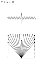
- Fig. 5 is a diagram showing a viewing field distribution of infrared ray sensor in the second embodiment.
- Fig. 6 is a diagram showing a viewing field distribution of distance sensor in the second embodiment.
- Fig. 7 is a partially cut-away perspective view of a thermal object measuring apparatus in a third embodiment of the invention.
- Fig. 8 is a time chart of sensor signal of distance sensor in the third embodiment.
- Fig. 9 is a partially cut-away perspective view of a thermal object measuring apparatus in a fourth embodiment of the invention.
- Fig. 10 is a block diagram of a thermal object measuring apparatus in a fifth embodiment of the invention.
- Fig. 11 is a perspective view showing a measuring state in the fifth embodiment.
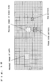
- Fig. 12 is a pattern diagram showing results of measurement in the fifth embodiment.
- Fig. 13 (A) is an outline structural diagram of distance sensor in an eighth embodiment of the invention, and (B) is a schematic diagram showing its detection viewing field distribution.
- Fig. 14 is a plan view showing a sixth embodiment of the invention.
- Fig. 15 is a block diagram showing a seventh embodiment of the invention.
- Fig. 16 is a block diagram showing a ninth embodiment of the invention.
- Fig. 17 is a schematic diagram of measuring space in a tenth embodiment of the invention.
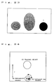
- Fig. 18 is a two-dimensional thermal image in a measuring space in Fig. 17.
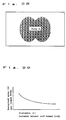
- Fig. 19 is a graph showing the relation between detecting area (a) in thermal image and sensor-object distance (r).
- Fig. 20 is a graph showing the relation between infrared ray sensor output (b) and sensor-object distance (r).
- Fig. 21 shows the mode after correction of thermal image in Fig. 18 by distance factor.
- Fig. 22 is a schematic diagram of measuring space in an eleventh embodiment of the invention.
- Fig. 23 shows a thermal image after correction by distance factor in the measuring space in Fig. 22.
- Fig. 24 is a schematic diagram of measuring space in a twelfth embodiment of the invention.
- Fig. 25 is an echo pattern (a) by ultrasonic sensor in the measuring space in Fig. 24.
- Fig. 26 is a two-dimensional thermal image (b) by infrared ray sensor in the measuring space in Fig. 24.
- Fig. 27 is a schematic diagram of measuring space in a thirteenth embodiment of the invention.
- Fig. 28 is a two-dimensional thermal image in the measuring space in Fig. 27.
- Fig. 29 shows the relation between the detected area per human body in two-dimensional thermal image and sensor-human distance.
- Fig. 30 is a schematic diagram of human body detecting apparatus in a fourteenth embodiment of the invention.
- Fig. 31 is a perspective view showing the two dimensional infrared ray sensor and the two dimensional infrared LED and the two dimensional photo diode of embodiment of the invention.
- Fig. 1 is a structural diagram showing an outline of a thermal object measuring apparatus in a first embodiment of the invention.
- a chopper 6 is provided for connecting and disconnecting the infrared ray entering a photo sensor
- a distance sensor 4 as distance detecting means is composed of an infrared LED 2 which is an infrared ray emitting element and a photo diode 3 which is a light receiving element.
- the infrared ray sensor 1 and distance sensor 4 are connected to a motor 7 as rotary scanning means so as to be free to rotate right and left about a rotary shaft 5.
- the confronting direction of the infrared ray sensor 1 and the confronting direction of the distance sensor 4 are adjusted to face the same direction.
- the motor 7 is driven to rotate the infrared ray sensor 1 about the rotary shaft 5, then a sensor output corresponding to the temperature difference of the chopper 6 and an object is obtained when the infrared ray sensor 1 confronts the object of which radiation temperature is different from that of the chopper 6.
- the distance sensor 4 as shown in the time chart in Fig. 2, projects an amplitude-modulated light (near infrared ray) from the infrared LED 2, and the returning light reflected by the object is received by the photo diode 3, and therefore the distance from the sensor to the object can be determined on the basis of the time difference between the projecting waveform and the receiving waveform and the light speed.
- Fig. 3 shows the output waveform (top) of the infrared ray sensor 1 when measuring a person standing before the apparatus, and the distance distribution (bottom, solid circle) from sensor to person measured by the distance sensor 4.
- the optical axes of the infrared ray sensor 1 and distance sensor 5 are adjusted parallel to the floor.
- a sensor output corresponding to the temperature difference between the confronting viewing field and chopper 6 is thereby generated in the infrared ray sensor 1.
- the distance sensor 4 emits light to the confronting viewing field from the infrared LED 2, receives the reflected light from the object in the photo diode 3, and calculates the distance from the time difference.
- the motor 7 is operated, and the motor 7 is stopped in the next viewing field, and emission from the infrared LED 2, reception by the photo diode 7, and distance calculation are repeated.
- Fig. 3 it is known that an object of high temperature is present in the ninth viewing field from start of rotation of the motor 7, and is located before toward the apparatus from the wall.
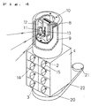
- Fig. 4 is a partially cut-away perspective view of a thermal object measuring apparatus in a second embodiment of the invention.
- the infrared ray radiated from the thermal object is intermittently interrupted of its optical path by a cylindrical chopper 9.
- the light is further condensed by an infrared ray condenser lens 11, and is focused on the photo sensor inside an infrared ray array sensor 8 through a slit 13 of the infrared ray array sensor 8.
- the infrared ray condenser lens 11 and infrared ray array sensor 8 are supported by a sensor fixing unit 12.
- the infrared ray array sensor 8 comprises eight photo sensors, and the viewing field distribution in the vertical direction with the sensor installed as a height of 1.2 m is shown in Fig. 5.
- the viewing field that can be detected by one photo sensor is a range from a sold line to a solid line, at 6 degrees in the vertical direction. Therefore, the total of eight photo sensors is 48 degrees.
- the distance sensor 5 is installed beneath the infrared ray sensor 10, and the optical axes in the horizontal direction are adjusted to be in same direction.
- the near infrared ray emitted from the infrared LED 2 is condensed into a beam of angle of 1 degree by a lens 15 for infrared LED, and is projected on the object.
- the returning beam reflected by the object is condensed by a lens 14 for photo diode and enters the photo diode 3.
- the number of infrared LEDs 2 and photo diodes 3 is four respectively, and the viewing field distribution in the vertical direction by installing the sensor at a height of 1.2 m is shown in Fig. 6.
- the single-dot chain line refers to the optical axes of near infrared ray, and they are arranged in the vertical direction so as to detect a lying person on the floor, a sitting person, and a standing person by the window.
- the optical axes in the vertical direction of each pair of infrared LED 2 and photo diode 3 are in coincidence.
- the infrared ray sensor 10 and distance sensor 4 are fixed on a sensor turntable 20.
- a stepping motor 21 rotates, its driving force is transmitted to the sensor turntable 20 through a rotary belt 22.
- a cylindrical chopper 9 is rotated by the infrared ray sensor 10, and the one-dimensional temperature distribution of the space is measured, while, at the same time, the one-dimensional distance distribution of the space is measured by the distance sensor 4. Consequently, rotating the stepping motor 21 by a specific angle, the sensor is directed to the next viewing field and is stopped.
- the one-dimensional temperature distribution and distance distribution of the space are measured in the same manner as mentioned above.
- continuous viewing fields are measured, and by connecting the information, two-dimensional temperature distribution and distance distribution of the space are obtained.
- Fig. 7 is a partially cut-away perspective view of a third embodiment, modifying the thermal object measuring apparatus of embodiment 2.
- the measuring procedure is same as explained in embodiment 2, but this embodiment is simplified in structure of apparatus by using only one lens 14 for photo diode and one photo diode 3. In order not to sacrifice the precision, the lens 14 for photo diode is wider in area. Eight infrared LEDs 2 are used.
- a time chart of sensor signal of the distance sensor 4 is shown in Fig. 8.
- emission by the first infrared LED 2 and emission by the second infrared LED 2 are delayed by 10 ⁇ sec each, if the distance to the object is not more than scores of meters, the reflected light returning from the object arrives at a delay of within 100 nsec, and hence it is easy to measure by sampling by measuring the timing.
- Fig. 9 is a partially cut-away perspective view of a fourth embodiment, modifying the thermal object measuring apparatus of embodiment 3.
- the measuring procedure is same as explained in embodiment 2 and embodiment 3, but this embodiment is simplified in structure of apparatus by using one lens 15 for infrared LEd disposed on the front side of the infrared LEDs 2 disposed in an array. So as not to sacrifice the precision, the lens 15 for infrared LED is wider in area. Of course, each optical axis of the arrayed infrared LEDs 2 is adjusted. In this method, the number of parts can be curtailed and the size is reduced without lowering the precision.
- Fig. 10 is a block diagram of a thermal object measuring apparatus in a fifth embodiment of the invention.
- an analog signal obtained from the infrared sensor 10 is A/D converted in an infrared ray sensor signal processor 25.
- the sensor signal obtained from the distance sensor 4 is A/D converted as distance information in a distance sensor signal processor 26.
- the two-dimensional temperature distribution information of the space outputted from the distance sensor signal processor 25 is displayed in a thermal image display unit 27 by using a color display suited to each temperature.
- the two-dimensional distance distribution outputted from the distance sensor signal processor 26 is displayed in a distance distribution display unit 38 by using a color display suited to each distance.
- the infrared ray sensor signal processor 25 and the distance sensor signal processor 26 compose sensor signal processing means
- the thermal image display unit 27 and distance distribution display unit 28 compose image display means.
- any corresponding unit disclosed in embodiment 1 to embodiment 4 may be used.
- Fig. 11 is a diagram showing a mode of measurement by using the thermal object measuring apparatus in the fifth embodiment.
- the room shown in Fig. 11 there are closet 33 and sofa 32, and a sensor unit of the thermal object measuring apparatus of this embodiment is installed on the wall.
- a sensor unit of the thermal object measuring apparatus of this embodiment is installed on the wall.
- the distance image of an unmanned room is preliminarily measured by the distance sensor.
- the sensor unit 31 is actuated to measure the two-dimensional thermal image by the infrared ray sensor and the distance image of the object by the distance sensor.
- the distance image cuts out the newly emerging object image by the difference from the distance image of the initial state measured preliminarily. Therefore, the sofa 32 is initially present and is not produced as object image.
- the result is shown in Fig. 12 together with the thermal image obtained by the infrared sensor.
- the dark area indicates the thermal image, and the shaded area is the object pattern cut out from the distance image.
- the thermal image is recognized at the position of the human body 34 and near the sofa 32, and in the object pattern cutout from the distance image, the position of the human body 34 and the position of bag 36 are confirmed.
- two persons are judged at the position of the actual human body 34 and at the position of the sofa 32, and if judged by the data of the distance sensor only, two persons are also newly judged at the position of the actual human body 34 and at the position of the bag 36 as invading objects.
- the thermal image and object detection of the newly invading objects, only the human body overlaps with the thermal image, so that one human body is judged, and thereby the human body can be detected precisely.
- Fig. 14 is a plan view explaining a sixth embodiment of the invention.
- the infrared ray sensor 1 and distance sensor 4 rotate on a same rotary shaft, but in this embodiment they are fixed in the upper part of a sensor fixing table on each independent rotary shaft.
- a DC servo motor 21 rotates, its driving force is transmitted to the sensor fixing table 20 through a rotary belt 22. Since the infrared ray sensor 1 and distance sensor 4 are mounted on independent rotary shafts, the infrared ray sensor 1 is less affected by the thermal generation of the distance sensor 4, and the height of the apparatus itself can be lowered, too. Therefore, this apparatus can be easily incorporated into television or other appliances.
- the means for transmitting the driving force of the DC servo motor 21 is not limited to belt, but gear or others may be also used.
- Fig. 15 is a diagram explaining a seventh embodiment of the invention, in which an analog signal obtained from the infrared ray sensor 10 is A/D converted in the infrared ray sensor signal processor 25.
- the sensor signal obtained from the distance sensor 4 is A/D converted as the distance information by the distance sensor signal processor 26.
- a temperature characteristic compensation unit 41 provided in the apparatus compensates for temperature of the distance sensor 4. That is, the temperature characteristic compensation unit 41 compensates for the distance data in the distance sensor signal processor 26. This compensation enhances the detection precision. Others are same as in other embodiments.
- Fig. 13 is a diagram for explaining an eighth embodiment of the invention, in which (A) is an outline structural diagram showing the distance sensor in the thermal object measuring apparatus of the embodiment, and (B) is a schematic diagram showing the detected viewing field distribution of the distance sensor.
- the distance sensor in this embodiment comprises a plurality (eight in this example) of pairs of infrared LEDs 2 and photo diodes 3, disposed in a horizontal direction., and the detecting direction of each pair of infrared LED 2 and photo diode 3 is set at an interval of, for example, 5 degrees within the horizontal plane as shown in Fig. 13 (B).
- the infrared ray sensor as thermal sensor, any one of infrared ray sensors disclosed in embodiment 1 to embodiment 7 may be incorporated.
- This embodiment is effective when information at a certain height can be obtained in the vertical direction, and rotary scanning is not necessary as the distance sensor, so that the measuring time is short. Moreover, since the infrared ray is used for distance detection, as compared with the distance sensor using ultrasonic waves, a distance distribution within a horizontal plane can be obtained in an extremely short time up to a long distance.
- the interval in the detecting direction is 5 degrees, but it may be freely adjusted to the rotary scanning interval of the infrared ray sensor.
- the distance distribution up to a long distance can be obtained in a very short time, it may be also considered to be applied as a distance detector, by making use of the distance sensor only, for detecting distance of, for example, plural moving objects, or separating individual moving objects.
- Fig. 16 is a diagram explaining a viewer survey system in a ninth embodiment of the invention.
- the thermal object measuring apparatus is placed on a television or the like, and its people counter 42 counts the number of human bodies in the sensor detection range on the basis of the signal from the infrared ray sensor 10 and distance sensor 4.
- a television data processor 44 outputs the television on/off state, and the channel and time zone of the program being presently broadcast.
- the people before the television enter the status of viewing by using the individual remote controllers through a data input unit 43.
- Judging means 46 enters the output from the data input unit 43 and output from the people counter 42, and judges if the both coincide or not.
- a data transmitter 45 transmits the information from the television data processor 44 to the viewer survey center through telephone circuit or the like. If not coinciding, the judging means 46 warns the people before the television by sounding the buzzer or flickering the LED, urging the input of the status of viewing. The viewer manipulates the data input unit 43 in reaction to the warning.
- infrared LEDs are used as infrared ray emitting devices, but not limited to them, for example, infrared ray laser diode and others may be also used.
- photo diodes are used as light receiving elements, but photo transistors and others may be similarly used.
- the number of infrared LEDs in the distance sensor was either four or eight, but the number of infrared LEDs is not particularly limited.
- Fig. 31 shows the two dimensional type apparatus. That is 1' is a two dimensional infrared ray sensor and 2' is a two dimensional infrared LED and 3' is a two dimensional photo diode. Such apparatus can get thermal image without rotation of the apparatus.
- Fig. 17 shows an outline of a tenth embodiment of the invention, in which the measuring space is seen from above.
- Two thermal objects are identical objects and the surface temperature is supposed to be same.
- the thermal image by the pyroelectric type two-dimensional infrared ray detecting apparatus is as shown in Fig. 18. It shows the output of the infrared ray sensor is greater when the color is deeper.
- the thermal object A closer to the position of the detecting apparatus is detected as being larger, and the remote thermal object B as being smaller.
- the output or temperature level of the infrared ray sensor element is high in the thermal object A closer to the detecting apparatus, and lower in the remote thermal object B.
- the detection area (a) of thermal image of two-dimensional thermal image of a thermal object of a certain size is inversely proportional to the square of the distance (r) from the sensor.
- the output temperature of the infrared ray sensor element since this detecting apparatus operates by light condensation by the lens, the period in which the portion having a certain surface temperature is out of the viewing field of the sensor because it is close to the sensor as shown in Fig. 20 is constant (left side of the diagram). However, where (r) is greater, it becomes a mean output in the entire detected region, and hence the temperature output of the infrared ray sensor element decreases (right side of the drawing).
- the size or surface temperature of the thermal object can be specified accurately.
- Fig. 21 shows correction of thermal image in Fig. 18 by the distance information by the object detecting means. After correction, both were detected at same size and same temperature level.
- Fig. 23 shows a thermal image obtained by correction of the two-dimensional thermal image by the infrared ray detecting apparatus in the measuring space in Fig. 22 by using the distance information obtained by using the object position detecting means.
- Reference numeral 1 denotes an infrared ray detecting apparatus
- 62 is a portable computer
- 63 is a human body
- 64 is a heating unit.
- Object (a) is similar to the human body in the temperature level, but is very small in size as compared with human body (b). Since it is corrected, (a) is judged not to be a human body.
- a very hot object such as the heating unit 64 and the human body (a) can be distinguished, and the human body can be judged at higher precision. In this method, an object over 50 degrees Celsius can be judged.
- a plurality of pyroelectric type infrared ray sensor elements 81 disposed in an array are used, and an ultrasonic sensor 82 for transmitting ultrasonic waves and receiving reflected waves is used as object position detecting means, and their directions are continuously rotated.
- Two-dimensional thermal images and ultrasonic echo patterns obtained by such apparatus are shown in Fig. 25 and Fig. 26.
- Reference numeral 83 is a thermal object.
- the position of the thermal object in the two-dimensional thermal image can be identified, and by correcting the thermal image (Fig. 26) by the distance between the sensor 81 and object 83 obtained therefrom, the size and temperature level of the thermal object can be determined precisely.
- the newly entering object can be detected, and it is possible to decrease the judging errors of taking non-human objects as human bodies.
- Fig. 28 shows a two-dimensional thermal image by infrared ray detecting means in the measuring space in Fig. 27.
- Plural human bodies 47 are very close to each other, and they are detected as one big thermal image (area A) in the thermal image.
- area A the thermal image
- the countermeasure preliminarily, the relation between the distance between the infrared ray detecting apparatus 1 and human body 47, and the detection area (a) per human body 47 is investigated, and a curve as shown in Fig. 29 is plotted.
- the detecting area per human body 47 is obtained from the distance (r) obtained by the object position detecting means, and the area of the detected thermal image is divided (A/a), so that the number of human bodies 47 contained in the thermal image can be calculated.
- Fig. 30 shows an outline of a detecting system of the number and position of people existing in a room composed of an infrared ray detecting apparatus 91 as infrared ray detecting means and an ultrasonic detecting apparatus as object position detecting means.
- Output signals from the infrared ray detecting apparatus 91 and ultrasonic wave detecting apparatus 92 are recomposed into two-dimensional thermal image and ultrasonic echo pattern by a signal processing apparatus 93, and sent into a data processing apparatus 94.
- the data processing apparatus 94 as correcting means, the transmitted two-dimensional thermal image is corrected by distance factor, and the human body is extracted by the detecting method from the corrected thermal image, and the number of people in the room is calculated.
- the result is displayed in a display device 95, and is recorded in a stationary memory or the like by a recording apparatus 96.
- the object position detecting means of the invention may be means for measuring the distance by transmitting electromagnetic waves and receiving reflected waves. Of course it may be means for measuring the distance by making use of the infrared ray sensor.
- the sensor signal processing means, thermal object detecting means, and other means are composed of exclusive hardware, but instead similar functions may be also composed in the software by using computers.
- the apparatus for detecting thermal object can be manufactured at low cost and in small size, and the detecting precision can be enhanced.
Landscapes
- Engineering & Computer Science (AREA)
- Physics & Mathematics (AREA)
- General Physics & Mathematics (AREA)
- Radar, Positioning & Navigation (AREA)
- Remote Sensing (AREA)
- Computer Networks & Wireless Communication (AREA)
- Spectroscopy & Molecular Physics (AREA)
- Electromagnetism (AREA)
- Multimedia (AREA)
- Toxicology (AREA)
- Health & Medical Sciences (AREA)
- Computer Security & Cryptography (AREA)
- Signal Processing (AREA)
- Human Computer Interaction (AREA)
- Theoretical Computer Science (AREA)
- Geophysics And Detection Of Objects (AREA)
- Radiation Pyrometers (AREA)
- Measurement Of Optical Distance (AREA)
- Optical Radar Systems And Details Thereof (AREA)
- Length Measuring Devices By Optical Means (AREA)
Priority Applications (1)
| Application Number | Priority Date | Filing Date | Title |
|---|---|---|---|
| EP99125247A EP1026521B1 (fr) | 1995-04-12 | 1996-04-11 | Méthode et appareil pour détecter un objet |
Applications Claiming Priority (4)
| Application Number | Priority Date | Filing Date | Title |
|---|---|---|---|
| JP8712995 | 1995-04-12 | ||
| JP87129/95 | 1995-04-12 | ||
| JP7126366A JPH08320258A (ja) | 1995-05-25 | 1995-05-25 | 熱画像情報と位置情報を利用した物体検出方法およびその装置 |
| JP126366/95 | 1995-05-25 |
Related Child Applications (1)
| Application Number | Title | Priority Date | Filing Date |
|---|---|---|---|
| EP99125247A Division EP1026521B1 (fr) | 1995-04-12 | 1996-04-11 | Méthode et appareil pour détecter un objet |
Publications (2)
| Publication Number | Publication Date |
|---|---|
| EP0737869A2 true EP0737869A2 (fr) | 1996-10-16 |
| EP0737869A3 EP0737869A3 (fr) | 1997-08-20 |
Family
ID=26428437
Family Applications (2)
| Application Number | Title | Priority Date | Filing Date |
|---|---|---|---|
| EP96105724A Ceased EP0737869A3 (fr) | 1995-04-12 | 1996-04-11 | Appareil de mesure thermique d'un objet, système d'estimation de l'audience de téléspectateurs, télémètre, méthode et dispositif thermique pur détecter un objet |
| EP99125247A Expired - Lifetime EP1026521B1 (fr) | 1995-04-12 | 1996-04-11 | Méthode et appareil pour détecter un objet |
Family Applications After (1)
| Application Number | Title | Priority Date | Filing Date |
|---|---|---|---|
| EP99125247A Expired - Lifetime EP1026521B1 (fr) | 1995-04-12 | 1996-04-11 | Méthode et appareil pour détecter un objet |
Country Status (3)
| Country | Link |
|---|---|
| US (2) | US5877688A (fr) |
| EP (2) | EP0737869A3 (fr) |
| DE (1) | DE69633524T2 (fr) |
Cited By (8)
| Publication number | Priority date | Publication date | Assignee | Title |
|---|---|---|---|---|
| EP1107204A3 (fr) * | 1999-12-11 | 2002-08-14 | Charles Harold Barker | Système de surveillance infrarouge |
| US20140140368A1 (en) * | 2012-11-19 | 2014-05-22 | Kaz Usa, Inc. | Non-contacxt medical thermometer with distance sensing and compensation |
| EP2247232A4 (fr) * | 2008-01-16 | 2014-11-05 | Welch Allyn Inc | Dispositif de mesure de température ir et de guidage avec couvercle de sonde |
| CN106096709A (zh) * | 2016-06-27 | 2016-11-09 | 云南瑞博检测技术股份有限公司 | 一种人流量计数传感器及其制作方法 |
| CN106094884A (zh) * | 2016-06-28 | 2016-11-09 | 江西省聚云科技有限公司 | 智能节能控制装置 |
| EP3274676A4 (fr) * | 2015-03-23 | 2018-11-07 | The Trustees of Princeton University | Capteur de température moyenne de rayonnement à mouvement sphérique |
| CN112489390A (zh) * | 2020-07-13 | 2021-03-12 | 广元量知汇科技有限公司 | 一种基于智能安防的安防节点协同报警方法 |
| US11035736B2 (en) | 2016-08-04 | 2021-06-15 | Sony Corporation | Image processing apparatus and image processing method |
Families Citing this family (92)
| Publication number | Priority date | Publication date | Assignee | Title |
|---|---|---|---|---|
| FI960162A0 (fi) * | 1996-01-12 | 1996-01-12 | Jouko Rautanen | Anlaeggning och foerfarande foer personbevakning pao vidstaeckta omraoden, i synnerhet utomhus |
| US6089750A (en) * | 1997-09-30 | 2000-07-18 | Sumitomo Electric Industries, Ltd. | Noncontact temperature distribution measuring apparatus |
| AU2305999A (en) * | 1997-11-25 | 1999-06-15 | Board Of Regents, The University Of Texas System | Object presence detection using dual wavelength bands |
| ATE248356T1 (de) * | 1998-01-30 | 2003-09-15 | Tecnimed Srl | Infrarot thermometer |
| JPH11348695A (ja) * | 1998-06-09 | 1999-12-21 | Nec Corp | 後方車両検知装置 |
| EP0973137B1 (fr) * | 1998-07-06 | 2003-01-08 | Siemens Building Technologies AG | Détecteur de mouvement |
| JP4285911B2 (ja) * | 1998-07-09 | 2009-06-24 | シーメンス アクチエンゲゼルシヤフト | 対象体の空間位置を求める装置および方法 |
| JP3420079B2 (ja) * | 1998-09-29 | 2003-06-23 | 松下電器産業株式会社 | 状態検知システム |
| DE19962201A1 (de) * | 1999-09-06 | 2001-03-15 | Holger Lausch | Verfahren und Anordnung zur Erfassung und Analyse des Rezeptionsverhaltens von Personen |
| US6252506B1 (en) * | 1999-09-22 | 2001-06-26 | Yuan-Tai Hsieh | Device for finding a position of a human |
| US6359564B1 (en) | 1999-10-28 | 2002-03-19 | Ralph W. Thacker | Occupancy status indicator |
| US6587049B1 (en) | 1999-10-28 | 2003-07-01 | Ralph W. Thacker | Occupant status monitor |
| AT412030B (de) * | 2000-04-07 | 2004-08-26 | Riegl Laser Measurement Sys | Verfahren zur aufnahme eines objektraumes |
| AU2001253523A1 (en) * | 2000-04-14 | 2001-10-30 | Kirkwood Industries, Inc. | Method and apparatus for testing commutators |
| US20020040280A1 (en) * | 2000-09-29 | 2002-04-04 | Morgan Stephen A. | System and method for refrigerant-based air conditioning system diagnostics |
| US8822623B2 (en) | 2001-11-14 | 2014-09-02 | Essilor International (Compagnie Generale D'optique) | High index and high impact resistant poly(thio)urethane/urea material, method of manufacturing same and its use in the optical field |
| JP2005037320A (ja) * | 2003-07-18 | 2005-02-10 | Sharp Corp | 人体検出装置およびそれを備えた電子機器 |
| JP2006010506A (ja) * | 2004-06-25 | 2006-01-12 | Sharp Corp | 光学式測距センサおよび自走式掃除機 |
| US20060231782A1 (en) * | 2005-04-14 | 2006-10-19 | Masco Corporation | CCD camera element used as actuation detector for electric plumbing products |
| MX2008014700A (es) * | 2006-05-18 | 2009-11-02 | Nielsen Co Us Llc | Metodos y aparato para medidores instalados colaboradores. |
| USRE46672E1 (en) | 2006-07-13 | 2018-01-16 | Velodyne Lidar, Inc. | High definition LiDAR system |
| US8289372B2 (en) * | 2006-10-16 | 2012-10-16 | Flir Systems Ab | Method for displaying a thermal image in an IR camera and an IR camera |
| US9191583B2 (en) | 2006-10-16 | 2015-11-17 | Flir Systems Ab | Method for displaying a thermal image in an IR camera, and an IR camera |
| GB2443664A (en) * | 2006-11-10 | 2008-05-14 | Autoliv Dev | An infra red object detection system de-emphasizing non relevant hot objects |
| US7746236B2 (en) * | 2007-05-01 | 2010-06-29 | Honeywell International Inc. | Fire detection system and method |
| JP5377837B2 (ja) * | 2007-05-31 | 2013-12-25 | 株式会社キーエンス | 光電センサ |
| EP2318804B1 (fr) * | 2008-04-17 | 2017-03-29 | Shilat Optronics Ltd | Système d'alarme d'intrusion |
| TWI372370B (en) * | 2008-06-16 | 2012-09-11 | Ind Tech Res Inst | Thermal detection system and detection method thereof |
| US8229228B2 (en) * | 2008-09-16 | 2012-07-24 | Robert Bosch Gmbh | Image analysis using a pre-calibrated pattern of radiation |
| US8186873B1 (en) * | 2008-10-08 | 2012-05-29 | Flir Systems, Inc. | Determination of thermal resistance using infrared thermography |
| US20100097226A1 (en) * | 2008-10-22 | 2010-04-22 | Leviton Manufacturing Co., Inc. | Occupancy sensing with image and supplemental sensing |
| US20100169908A1 (en) * | 2008-12-30 | 2010-07-01 | Nielsen Christen V | Methods and apparatus to enforce a power off state of an audience measurement device during shipping |
| US8156517B2 (en) | 2008-12-30 | 2012-04-10 | The Nielsen Company (U.S.), Llc | Methods and apparatus to enforce a power off state of an audience measurement device during shipping |
| US8375404B2 (en) * | 2008-12-30 | 2013-02-12 | The Nielsen Company (Us), Llc | Methods and apparatus to enforce a power off state of an audience measurement device during shipping |
| US9674458B2 (en) * | 2009-06-03 | 2017-06-06 | Flir Systems, Inc. | Smart surveillance camera systems and methods |
| US20120116252A1 (en) * | 2010-10-13 | 2012-05-10 | The Regents Of The University Of Colorado, A Body Corporate | Systems and methods for detecting body orientation or posture |
| US20120106778A1 (en) * | 2010-10-28 | 2012-05-03 | General Electric Company | System and method for monitoring location of persons and objects |
| US9143703B2 (en) | 2011-06-10 | 2015-09-22 | Flir Systems, Inc. | Infrared camera calibration techniques |
| EP2713213B1 (fr) * | 2012-09-03 | 2022-01-19 | Konica Minolta, Inc. | Appareil de formation d'images, procédé de commande de puissance et support d'enregistrement |
| US9640052B2 (en) * | 2014-04-25 | 2017-05-02 | Wen-Sung Lee | Home intellectual positioning system |
| WO2015182066A1 (fr) * | 2014-05-30 | 2015-12-03 | パナソニック株式会社 | Capteur de température, dispositif l'utilisant, et procédé de mesure de température |
| US9869753B2 (en) | 2014-08-15 | 2018-01-16 | Quanergy Systems, Inc. | Three-dimensional-mapping two-dimensional-scanning lidar based on one-dimensional-steering optical phased arrays and method of using same |
| US10036803B2 (en) | 2014-10-20 | 2018-07-31 | Quanergy Systems, Inc. | Three-dimensional lidar sensor based on two-dimensional scanning of one-dimensional optical emitter and method of using same |
| KR102282459B1 (ko) * | 2015-02-25 | 2021-07-27 | 한화테크윈 주식회사 | 사람 계수 시스템 및 방법 |
| DE102015208960A1 (de) * | 2015-05-15 | 2016-11-17 | Vaillant Gmbh | Heizungs-Lüftungs-Klimatechnik-System |
| CN105068140A (zh) * | 2015-07-23 | 2015-11-18 | 柳州铁道职业技术学院 | 小范围内人体位置检测装置 |
| US9826918B2 (en) | 2015-08-28 | 2017-11-28 | Juergen Marx | Method and device for detecting the surface structure and properties of a probe |
| US10006983B2 (en) * | 2015-10-21 | 2018-06-26 | Everspring Industry Co., Ltd. | Apparatus and method for detecting azimuthal angle of heat source |
| US10627490B2 (en) | 2016-01-31 | 2020-04-21 | Velodyne Lidar, Inc. | Multiple pulse, LIDAR based 3-D imaging |
| CA3017735C (fr) | 2016-03-19 | 2023-03-14 | Velodyne Lidar, Inc. | Eclairage et detection integres pour imagerie 3d basee sur lidar |
| WO2017184172A1 (fr) * | 2016-04-22 | 2017-10-26 | Hewlett-Packard Development Company, L.P. | Détermination de distance |
| US10228289B2 (en) * | 2016-05-13 | 2019-03-12 | Google Llc | Detecting occupancy and temperature with two infrared elements |
| WO2017210418A1 (fr) | 2016-06-01 | 2017-12-07 | Velodyne Lidar, Inc. | Lidar à balayage à pixels multiples |
| US10495518B2 (en) * | 2016-06-23 | 2019-12-03 | Panasonic Intellectual Property Management Co., Ltd. | Infrared detection apparatus |
| JP6765064B2 (ja) * | 2016-06-23 | 2020-10-07 | パナソニックIpマネジメント株式会社 | 赤外線検出装置 |
| USD871412S1 (en) * | 2016-11-21 | 2019-12-31 | Datalogic Ip Tech S.R.L. | Optical scanner |
| CN108260073B (zh) * | 2016-12-27 | 2021-02-09 | 光宝电子(广州)有限公司 | 闸道器、闸道器的安装方法以及物联网装置的安装方法 |
| JP7290571B2 (ja) | 2017-03-31 | 2023-06-13 | ベロダイン ライダー ユーエスエー,インコーポレイテッド | 統合化されたlidar照明出力制御 |
| JP2020519881A (ja) | 2017-05-08 | 2020-07-02 | ベロダイン ライダー, インク. | Lidarデータ収集及び制御 |
| US11294035B2 (en) | 2017-07-11 | 2022-04-05 | Nuro, Inc. | LiDAR system with cylindrical lenses |
| US11061116B2 (en) | 2017-07-13 | 2021-07-13 | Nuro, Inc. | Lidar system with image size compensation mechanism |
| US11009868B2 (en) | 2017-07-20 | 2021-05-18 | Nuro, Inc. | Fleet of autonomous vehicles with lane positioning and platooning behaviors |
| US11467574B2 (en) | 2017-07-20 | 2022-10-11 | Nuro, Inc. | Infrastructure monitoring system on autonomous vehicles |
| EP3659080A4 (fr) | 2017-07-28 | 2021-04-21 | Nuro, Inc. | Système et mécanisme de vente incitative de produits sur des véhicules autonomes |
| US10824862B2 (en) | 2017-11-14 | 2020-11-03 | Nuro, Inc. | Three-dimensional object detection for autonomous robotic systems using image proposals |
| US11294041B2 (en) * | 2017-12-08 | 2022-04-05 | Velodyne Lidar Usa, Inc. | Systems and methods for improving detection of a return signal in a light ranging and detection system |
| TWI704502B (zh) * | 2018-06-08 | 2020-09-11 | 晟風科技股份有限公司 | 具有對距離做溫度補償功能之熱像儀及其溫度補償方法 |
| US11836984B2 (en) * | 2018-06-29 | 2023-12-05 | Logistics and Supply Chain MultiTech R&D Centre Limited | Electronic device and method for counting objects |
| US11971507B2 (en) | 2018-08-24 | 2024-04-30 | Velodyne Lidar Usa, Inc. | Systems and methods for mitigating optical crosstalk in a light ranging and detection system |
| US10712434B2 (en) | 2018-09-18 | 2020-07-14 | Velodyne Lidar, Inc. | Multi-channel LIDAR illumination driver |
| US11082010B2 (en) | 2018-11-06 | 2021-08-03 | Velodyne Lidar Usa, Inc. | Systems and methods for TIA base current detection and compensation |
| CN109405976B (zh) * | 2018-11-08 | 2020-05-19 | 武汉高德智感科技有限公司 | 一种人体检验检疫系统温度自动修正方法 |
| US11885958B2 (en) | 2019-01-07 | 2024-01-30 | Velodyne Lidar Usa, Inc. | Systems and methods for a dual axis resonant scanning mirror |
| US12061263B2 (en) | 2019-01-07 | 2024-08-13 | Velodyne Lidar Usa, Inc. | Systems and methods for a configurable sensor system |
| US10613203B1 (en) | 2019-07-01 | 2020-04-07 | Velodyne Lidar, Inc. | Interference mitigation for light detection and ranging |
| US11964627B2 (en) | 2019-09-30 | 2024-04-23 | Nuro, Inc. | Methods and apparatus for supporting compartment inserts in autonomous delivery vehicles |
| JP7373777B2 (ja) | 2019-11-27 | 2023-11-06 | パナソニックIpマネジメント株式会社 | 赤外線処理システム、赤外線センサシステム、赤外線処理方法、及び、プログラム |
| KR102595870B1 (ko) * | 2020-03-04 | 2023-10-30 | 주식회사 유진로봇 | 초소형 라이다 센서 |
| CN115088001A (zh) | 2020-03-23 | 2022-09-20 | 纽诺有限公司 | 用于自主递送的方法和装置 |
| CN111458043A (zh) * | 2020-04-21 | 2020-07-28 | 深圳市速信智联科技有限公司 | 一种基于手机距离传感器的便携式测温设备 |
| CN111595453A (zh) * | 2020-05-27 | 2020-08-28 | 成都电科崇实科技有限公司 | 一种基于人脸识别的红外测温系统及方法 |
| US11373425B2 (en) | 2020-06-02 | 2022-06-28 | The Nielsen Company (U.S.), Llc | Methods and apparatus for monitoring an audience of media based on thermal imaging |
| CN112067134A (zh) * | 2020-07-31 | 2020-12-11 | 深圳市优必选科技股份有限公司 | 一种温度检测方法、装置、终端及存储介质 |
| US11553247B2 (en) | 2020-08-20 | 2023-01-10 | The Nielsen Company (Us), Llc | Methods and apparatus to determine an audience composition based on thermal imaging and facial recognition |
| US11763591B2 (en) | 2020-08-20 | 2023-09-19 | The Nielsen Company (Us), Llc | Methods and apparatus to determine an audience composition based on voice recognition, thermal imaging, and facial recognition |
| US11595723B2 (en) | 2020-08-20 | 2023-02-28 | The Nielsen Company (Us), Llc | Methods and apparatus to determine an audience composition based on voice recognition |
| DE102020131288A1 (de) * | 2020-11-26 | 2022-06-02 | Valeo Schalter Und Sensoren Gmbh | Verfahren zum Betreiben einer Detektionsvorrichtung zur Bestimmung von Entfernungsgrößen, Detektionsvorrichtung und Fahrzeug mit wenigstens einer Detektionsvorrichtung |
| US11804121B2 (en) * | 2021-04-01 | 2023-10-31 | Lenovo (Singapore) Pte. Ltd. | Human presence detector device |
| CN113660435B (zh) * | 2021-08-19 | 2022-05-17 | 东莞市鑫泰仪器仪表有限公司 | 一种红外夜视仪增益系统 |
| WO2023249723A1 (fr) * | 2022-06-22 | 2023-12-28 | Airhive Inc | Véhicule aérien sans pilote (uav) destiné à faciliter des livraisons aériennes de marchandises |
| US20260001667A1 (en) * | 2022-06-22 | 2026-01-01 | Airhive Inc. | Unmanned aerial vehicle (uav) for facilitating aerial deliveries of cargo |
| CN118427734A (zh) * | 2023-02-01 | 2024-08-02 | 光宝科技新加坡私人有限公司 | 人员存在检测模型的训练系统及训练方法 |
Family Cites Families (23)
| Publication number | Priority date | Publication date | Assignee | Title |
|---|---|---|---|---|
| US3781111A (en) * | 1972-03-16 | 1973-12-25 | Nasa | Short range laser obstacle detector |
| DE2802477C3 (de) * | 1978-01-20 | 1981-08-20 | Precitronic Gesellschaft für Feinmechanik und Electronik mbH, 2000 Hamburg | Einrichtung zum Senden und/oder Empfangen von Laserlicht mit mehreren Laserlicht emittierenden und/oder detektierenden optronischen Elementen |
| US4479053A (en) * | 1981-03-11 | 1984-10-23 | The United States Of America As Represented By The Administrator Of The National Aeronautics And Space Administration | Focal plane array optical proximity sensor |
| US4510390A (en) * | 1982-01-11 | 1985-04-09 | Jan Rajchman | Electronic method and apparatus for distance measurement through the use of equidistant thermal fiducial markings |
| DE3326215C2 (de) * | 1983-07-21 | 1986-04-03 | M.A.N.- Roland Druckmaschinen AG, 6050 Offenbach | Vorrichtung zum Aufspannen einer Druckplatte oder eines Gummituches |
| JPS60168111A (ja) * | 1984-02-13 | 1985-08-31 | Canon Inc | カメラの焦点調節装置 |
| US4567766A (en) * | 1984-03-20 | 1986-02-04 | Blackwelders | Piezoelectric ultrasonic apparatus and method for determining the distance from a predetermined point to a target |
| SE462999B (sv) * | 1987-05-29 | 1990-09-24 | Saab Missiles Ab | Anordning foer selektiv detektering av foeremaal |
| JPS63307378A (ja) * | 1987-06-09 | 1988-12-15 | Agency Of Ind Science & Technol | レ−ザレ−ダ視覚センサ |
| KR900000249B1 (ko) * | 1987-11-30 | 1990-01-24 | 주식회사 금성사 | 리얼타임 거리센서 |
| DE3816657A1 (de) * | 1988-05-17 | 1989-11-23 | Messerschmitt Boelkow Blohm | Einrichtung zur ausrichtung und ausloesung eines wirkkoerpers |
| US4858000A (en) * | 1988-09-14 | 1989-08-15 | A. C. Nielsen Company | Image recognition audience measurement system and method |
| US5031228A (en) * | 1988-09-14 | 1991-07-09 | A. C. Nielsen Company | Image recognition system and method |
| DE3991548C1 (de) * | 1989-01-09 | 1995-05-04 | Shogaku Ikueisha Kyoiku Kenkyusho | Elektrisches Gerät zum Ermitteln der Fenrsehprogramm-Einschaltquote |
| DE3905929C1 (en) * | 1989-02-25 | 1990-04-26 | Daimler-Benz Aktiengesellschaft, 7000 Stuttgart, De | Method and device for detecting side (cross) wind influencing the handling of a vehicle |
| US5026153A (en) * | 1989-03-01 | 1991-06-25 | Mitsubishi Denki K.K. | Vehicle tracking control for continuously detecting the distance and direction to a preceding vehicle irrespective of background dark/light distribution |
| US5107128A (en) * | 1989-05-05 | 1992-04-21 | Saskatchewan Power Corporation | Method and apparatus for detecting flame with adjustable optical coupling |
| JPH0387684A (ja) * | 1989-06-12 | 1991-04-12 | Omron Corp | 赤外線エリアセンサ |
| US4914734A (en) * | 1989-07-21 | 1990-04-03 | The United States Of America As Represented By The Secretary Of The Air Force | Intensity area correlation addition to terrain radiometric area correlation |
| US5568400A (en) * | 1989-09-01 | 1996-10-22 | Stark; Edward W. | Multiplicative signal correction method and apparatus |
| USH1066H (en) * | 1990-07-16 | 1992-06-02 | The United States Of America As Represented By The Secretary Of The Navy | Airborne infrared transmissometer |
| JPH05180632A (ja) * | 1991-12-26 | 1993-07-23 | I N R Kenkyusho:Kk | 三次元形状測定方法及びその装置 |
| DE9312118U1 (de) * | 1993-08-13 | 1993-09-23 | Siemens AG, 80333 München | Dual-bewegungsmelder zur detektion von intrudern |
-
1996
- 1996-04-11 DE DE69633524T patent/DE69633524T2/de not_active Expired - Fee Related
- 1996-04-11 EP EP96105724A patent/EP0737869A3/fr not_active Ceased
- 1996-04-11 EP EP99125247A patent/EP1026521B1/fr not_active Expired - Lifetime
- 1996-04-12 US US08/629,937 patent/US5877688A/en not_active Expired - Fee Related
-
1998
- 1998-07-27 US US09/122,771 patent/US5995206A/en not_active Expired - Fee Related
Cited By (14)
| Publication number | Priority date | Publication date | Assignee | Title |
|---|---|---|---|---|
| EP1107204A3 (fr) * | 1999-12-11 | 2002-08-14 | Charles Harold Barker | Système de surveillance infrarouge |
| EP2247232A4 (fr) * | 2008-01-16 | 2014-11-05 | Welch Allyn Inc | Dispositif de mesure de température ir et de guidage avec couvercle de sonde |
| US20180003563A1 (en) * | 2012-11-19 | 2018-01-04 | Helen Of Troy Limited | Non-contact medical thermometer with distance sensing and compensation |
| EP2920564A2 (fr) * | 2012-11-19 | 2015-09-23 | KAZ Europe SA | Thermomètre médical sans contact avec détection et compensation de distance |
| US20140140368A1 (en) * | 2012-11-19 | 2014-05-22 | Kaz Usa, Inc. | Non-contacxt medical thermometer with distance sensing and compensation |
| US10048134B2 (en) | 2012-11-19 | 2018-08-14 | Helen Of Troy Limited | Non-contact medical thermometer with distance sensing and compensation |
| EP3274676A4 (fr) * | 2015-03-23 | 2018-11-07 | The Trustees of Princeton University | Capteur de température moyenne de rayonnement à mouvement sphérique |
| CN106096709A (zh) * | 2016-06-27 | 2016-11-09 | 云南瑞博检测技术股份有限公司 | 一种人流量计数传感器及其制作方法 |
| CN106096709B (zh) * | 2016-06-27 | 2019-02-01 | 云南瑞博检测技术股份有限公司 | 一种人流量计数传感器及其制作方法 |
| CN106094884A (zh) * | 2016-06-28 | 2016-11-09 | 江西省聚云科技有限公司 | 智能节能控制装置 |
| CN106094884B (zh) * | 2016-06-28 | 2023-04-07 | 江西省聚云科技有限公司 | 智能节能控制装置 |
| US11035736B2 (en) | 2016-08-04 | 2021-06-15 | Sony Corporation | Image processing apparatus and image processing method |
| CN112489390A (zh) * | 2020-07-13 | 2021-03-12 | 广元量知汇科技有限公司 | 一种基于智能安防的安防节点协同报警方法 |
| CN112489390B (zh) * | 2020-07-13 | 2022-05-10 | 北京宏远汇通网络科技有限公司 | 一种基于智能安防的安防节点协同报警方法 |
Also Published As
| Publication number | Publication date |
|---|---|
| EP1026521B1 (fr) | 2004-09-29 |
| DE69633524D1 (de) | 2004-11-04 |
| DE69633524T2 (de) | 2005-03-03 |
| EP1026521A2 (fr) | 2000-08-09 |
| US5877688A (en) | 1999-03-02 |
| EP0737869A3 (fr) | 1997-08-20 |
| EP1026521A3 (fr) | 2000-11-22 |
| US5995206A (en) | 1999-11-30 |
Similar Documents
| Publication | Publication Date | Title |
|---|---|---|
| US5877688A (en) | Thermal object measuring apparatus | |
| US12306301B2 (en) | Determining positional information of an object in space | |
| US4949074A (en) | Method of intrusion detection | |
| US4952911A (en) | Scanning intrusion detection device | |
| US4903009A (en) | Intrusion detection device | |
| US4967183A (en) | Method of intrusion detection over a wide area | |
| JP3328500B2 (ja) | 熱物体測定装置、個人視聴率調査システム、及び距離検出器 | |
| JP3159869B2 (ja) | 熱物体検出装置および測定法 | |
| US8970374B2 (en) | Intrusion warning system | |
| CN1655197B (zh) | 监视装置 | |
| EP0828233A2 (fr) | Appareil pour détecter le nombre de passants | |
| WO1999003080A1 (fr) | Systeme de detection d'intrus | |
| CN109343079A (zh) | 一种测距避障方法及避障装置 | |
| JP3011121B2 (ja) | 警備システム | |
| US4749862A (en) | Scanning fire-monitoring system | |
| EP4455718A1 (fr) | Détection de parois et portes en verre et mesure de distance pour robots et son procédé de commande | |
| JPH09287913A (ja) | 物体位置検出装置、人体検出方法 | |
| Lu et al. | Passive people meters: A first step | |
| CN100451672C (zh) | 自动测定两个物体间相对方向的系统和实施方法 | |
| EP3875989B1 (fr) | Capteur de balayage laser | |
| WO2025238864A1 (fr) | Dispositif de surveillance | |
| JP3376437B2 (ja) | 人体検出方法および人体検出装置 | |
| JPS6332681A (ja) | 画像監視センサ |
Legal Events
| Date | Code | Title | Description |
|---|---|---|---|
| PUAI | Public reference made under article 153(3) epc to a published international application that has entered the european phase |
Free format text: ORIGINAL CODE: 0009012 |
|
| AK | Designated contracting states |
Kind code of ref document: A2 Designated state(s): DE FR GB |
|
| PUAL | Search report despatched |
Free format text: ORIGINAL CODE: 0009013 |
|
| AK | Designated contracting states |
Kind code of ref document: A3 Designated state(s): DE FR GB |
|
| 17P | Request for examination filed |
Effective date: 19980205 |
|
| 17Q | First examination report despatched |
Effective date: 19990601 |
|
| STAA | Information on the status of an ep patent application or granted ep patent |
Free format text: STATUS: THE APPLICATION HAS BEEN REFUSED |
|
| 18R | Application refused |
Effective date: 20060630 |