EP0737903A2 - Verfahren und Einrichtung zur Steuerung einer Bearbeitung in einer Werkzeugmaschine - Google Patents
Verfahren und Einrichtung zur Steuerung einer Bearbeitung in einer Werkzeugmaschine Download PDFInfo
- Publication number
- EP0737903A2 EP0737903A2 EP96420117A EP96420117A EP0737903A2 EP 0737903 A2 EP0737903 A2 EP 0737903A2 EP 96420117 A EP96420117 A EP 96420117A EP 96420117 A EP96420117 A EP 96420117A EP 0737903 A2 EP0737903 A2 EP 0737903A2
- Authority
- EP
- European Patent Office
- Prior art keywords
- tool
- machining
- contact
- current
- during
- Prior art date
- Legal status (The legal status is an assumption and is not a legal conclusion. Google has not performed a legal analysis and makes no representation as to the accuracy of the status listed.)
- Withdrawn
Links
Images

Classifications
-
- G—PHYSICS
- G05—CONTROLLING; REGULATING
- G05B—CONTROL OR REGULATING SYSTEMS IN GENERAL; FUNCTIONAL ELEMENTS OF SUCH SYSTEMS; MONITORING OR TESTING ARRANGEMENTS FOR SUCH SYSTEMS OR ELEMENTS
- G05B19/00—Program-control systems
- G05B19/02—Program-control systems electric
- G05B19/18—Numerical control [NC], i.e. automatically operating machines, in particular machine tools, e.g. in a manufacturing environment, so as to execute positioning, movement or co-ordinated operations by means of program data in numerical form
- G05B19/406—Numerical control [NC], i.e. automatically operating machines, in particular machine tools, e.g. in a manufacturing environment, so as to execute positioning, movement or co-ordinated operations by means of program data in numerical form characterised by monitoring or safety
- G05B19/4065—Monitoring tool breakage, life or condition
-
- B—PERFORMING OPERATIONS; TRANSPORTING
- B23—MACHINE TOOLS; METAL-WORKING NOT OTHERWISE PROVIDED FOR
- B23Q—DETAILS, COMPONENTS, OR ACCESSORIES FOR MACHINE TOOLS, e.g. ARRANGEMENTS FOR COPYING OR CONTROLLING; MACHINE TOOLS IN GENERAL CHARACTERISED BY THE CONSTRUCTION OF PARTICULAR DETAILS OR COMPONENTS; COMBINATIONS OR ASSOCIATIONS OF METAL-WORKING MACHINES, NOT DIRECTED TO A PARTICULAR RESULT
- B23Q17/00—Arrangements for observing, indicating or measuring on machine tools
- B23Q17/22—Arrangements for observing, indicating or measuring on machine tools for indicating or measuring existing or desired position of tool or work
- B23Q17/2233—Arrangements for observing, indicating or measuring on machine tools for indicating or measuring existing or desired position of tool or work for adjusting the tool relative to the workpiece
- B23Q17/2241—Detection of contact between tool and workpiece
Definitions
- the present invention relates to machine tools, in which a workpiece held by a workpiece spindle and tools held by a toolholder are moved relative to each other during a machining cycle to produce a workpiece .
- the invention relates in particular to bar turning machines such as single spindle lathes with fixed headstock or movable headstock, and multispindle lathes.
- control is carried out a posteriori, by measuring the dimensions of each piece obtained.
- a control requires a recovery of the part, and it is carried out too long after the production of the part, so that the following parts can also be defective when the defect has been found on said part.
- the result is a drop in yield and a drop in quality.
- the document EP-A-0 363 902 describes a device and a method for controlling machining by measuring and checking the electrical resistance of contact between the tool and the part.
- the document describes the means for accurately measuring the electrical contact resistance, eliminating the disturbing effect of the electromotive force appearing in the contact zone which is at high temperature during machining. To do this, an intermittent electric current is passed through the contact area between the workpiece and the tool, and the potential differences between the workpiece and the tool are measured.
- the contact resistance is deduced by calculation, and is compared with a series of contact resistance values corresponding both to the type of tool used and to the materials forming the workpiece.
- this device and this process do not take into account all the parameters that can disturb the measurement, in particular the presence of conductive or insulating cutting oil in the contact area, the nature of the material constituting the workpiece, the nature of the material constituting the tool, the shape of the tool and the part, the machining parameters.
- the method also requires the use of tools made of particular materials.
- the document EP-A-0 165 745 teaches to continuously measure, during machining, a parameter such as a short-circuit current, and to detect the rapid increase in the slope of this parameter indicating the imminence of '' a tool break. Only the imminent tool breakage is detected by this process. This does not make it possible to detect faults which, without breaking the tool, produce nevertheless defective parts.
- Document EP-A-0 509 817 describes a complex and expensive expert system for predicting the life of a tool, by recording several series of parameters during several machining cycles, and recording measurements of wear of the tool. This does not allow reliable control of the quality of the parts produced.
- the problem proposed by the present invention is to design a new method and a reliable and inexpensive device allowing the control of machining of series of electrically conductive parts by a tool on a machine tool during said machining, this control having to provide sufficient information to know the quality of the part that will be obtained, to avoid the production of a defective part, and to warn the user as soon as an intervention is necessary.
- the invention provides, during the machining cycle of certain at least parts, at least one control step during at least a predetermined limited time period of control, step during which an electrical voltage generator is connected between the tool holder and the workpiece spindle and it is checked that an appropriate contact electrical current, included in an admissible range of contact current, passes through the contact zone between the tool carried by the tool holder and the part held by the workpiece spindle, and a fault signal is produced in the event of detection of an inappropriate contact electric current during said control time range.
- the idea which is the basis of the invention is to carry out a control by associating the time variable and the quality variable of the contact between the tool and the part.
- the control is thus carried out precisely in the vicinity of well-defined times in the machining cycle of each part, times when the position of the tool holder, the position of the workpiece spindle, and all the other parameters which in principle determine the machining conditions must in principle be reproduced identically from one part to another.
- These identical machining conditions determine the quality of the contact between the part and the tool, quality which is detected by measurement and comparison of the electric current passing through the contact, to deduce therefrom whether the machining is normal or not.
- the quality of the mechanical contact between workpiece and tool is thus checked by measuring the electric current passing through the contact zone and by comparing it to at least one admissible threshold value of this electric contact current.
- the current electric contact is considered inappropriate if it does not have, during the time range, a sudden increase in appropriate amplitude indicating the establishment of contact.
- the method comprises a prior learning procedure during which the first series of parts is machined with the same tool, by checking a posteriori, by example in a known manner, using traditional or non-traditional verification instruments, the quality of the parts produced; the values of the electrical contact current passing through the part-tool contact zone are measured and stored during the steps of controlling the machining cycles of said parts of the first series, and said learning procedure is stopped when obtaining '' a defective first part and a corresponding measurement of the electrical contact current, the limit value of the admissible current range being chosen equal to the electrical contact current measured during the machining of the last correct part of said first series of rooms.
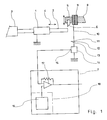
- the device is applied to a machine tool comprising at least one workpiece spindle 1 adapted to hold the workpiece 2.
- the workpiece 2 Before machining, the workpiece 2 is often in the form of a bar , pushed by a bar advancement device 3.
- the workpiece spindle 1 drives the workpiece 2 in rotation about its longitudinal axis, and can control the forward or backward movements of the workpiece 2 as illustrated by the arrow 4.
- Means are used to identify the position of spindle 1 during the machining cycle.
- a tool holder 5 is adapted to carry a tool 6 and to move it into the different machining positions desired during the machining cycle. Means make it possible to identify the position of the tool 6.
- Control means 7 are adapted to cause the movements of the functional members of the machine tool such as the workpiece spindle 1 and the tool holder 5 according to a succession of machining cycles.
- Each part execution cycle 2 includes one or more tool cycles starting at predetermined times during said part execution cycle.
- the tool holder 5 is mounted in displacement on traditional slides which are isolated from the frame 8 of the machine tool by insulating means 9.
- insulating means 9 can be interposed between the tool holder 5 and the tool 6. In all cases, the insulating means 9 electrically isolate the tool 6 relative to the frame 8 of the machine tool.
- the insulating means 9 comprise a layer of hard material and electrical insulator, to ensure both the electrical insulation of the tool 6 relative to the frame 8 and a rigid mechanical strength of the tool 6 to ensure good precision of machining.
- the hard and insulating material is a layer of polytetrafluoroethylene reinforced with glass fibers.
- the hard and insulating material is a layer of alumina.
- Electrical conductors 10 ensure the electrical connection of the tool 6 to the first output terminal 11 of an electrical voltage generator 12, the second terminal 13 of which is connected to the workpiece 2 during machining.
- the connection to the part 2 can pass through the workpiece pin 1, as illustrated in the figure, by the ground, or by a rotating contact or not with a specific conductor.
- a current sensor 14 is inserted in the electrical circuit formed by the conductors 10, and makes it possible to measure the electrical contact current in said conductors 10 and to produce on its output 15 a measurement signal sent to a comparator 17 which may be included in the control means 7.
- the invention provides a memory 16 for storing the limits of at least one control time range in the workpiece machining cycle, at the choice of the user.
- the invention further provides a threshold electrical signal generator 18, adapted to generate threshold electrical signals constituting admissible signal thresholds corresponding to an admissible range of contact current.
- the output of the threshold electrical signal generator 18 is connected to an input of the comparator 17, in order to send said threshold signals to the comparator 17.
- the threshold generator 18 can comprise the memory 16, in which a scale of contact current values is also recorded, comprising at least a threshold of admissible values I L from which the contact current I corresponds to a tool 6 having exceeded the admissible degree of wear to produce a correct part.
- the contact current is thus a physical parameter representative of the quality of the workpiece-tool contact.
- a simplified embodiment of the threshold generator can be a simple potentiometer, actuated by the user, and delivering a current or a fixed voltage chosen by the user to constitute a maximum or minimum threshold of admissible contact current values.
- the comparator 17 is adapted to scan the reception of the measurement signal at each time step of the control step defined in the memory 16, and to generate a fault signal in the event of the presence of a measurement signal whose value n ' is not admissible and indicates that the contact between the workpiece and the tool is not appropriate.
- the fault signal is used to warn the user and / or force the machining to stop or the tool to be changed.
- the current sensor 14 permanently provides a state of the contact current between the tool 6 and the part 2.
- This measurement of contact current also serves as a detection signal: in the absence of contact , the current measured is zero or very different from that which exists in the presence of contact, while in the presence of contact, the current takes a non-zero value.
- a zero or very different value of current detected by the current sensor 14 constitutes a detection signal.
- the comparator 17 can be adapted to compare, during each time range of control step, the measurement of contact electrical current received from the current sensor 14 and of the electrical contact current values recorded in the memory 16, and to generate a tool change signal when the measured contact current is not included in the admissible contact current values.
- the device shown in the figure performs a machining control comprising, for each part, at least one machining control step during which the workpiece spindle 1 and the tool holder 5 are in respective positions. predetermined machining, and during which the machining conditions are a priori the same for each part of a series of parts to be machined.
- this control step it is checked that an appropriate electric current, included in an admissible contact current range, crosses the contact zone between the tool 6 carried by the tool holder 5 and the part 2 held by the spindle workpiece carrier 1.
- the appropriateness or satisfaction of the electric current flowing through the contact zone between the tool and the workpiece is verified by measuring, at the predetermined machining instant, the electric current and by comparing it with the thresholds of admissible values.
- a fault signal is emitted which is later used in the machining cycle to generate the change of part or change of tool.
- FIG. 2 shows a possible variation of the electrical contact current I as a function of time during a tool cycle, that is to say during the machining of a part by a specific tool.
- a control step takes place during this tool cycle, and the value I 1 that the electric current I takes then is measured in the vicinity of this instant E.
- the invention makes it possible to eliminate the influence of numerous disturbing parameters capable of modifying the electric current I as a function of the machining conditions.
- the value I L limit of the admissible range of electrical contact current I is determined by a prior learning procedure, during which the first series of parts is machined with the same tool, checking a posteriori , using traditional verification instruments, the quality of the parts produced, the values of the electrical contact current I are measured and stored during the steps of controlling the machining cycles of said parts of the first series of parts, and said learning procedure is ceased upon obtaining a first defective part; the limit value I L of the admissible current range is chosen equal to the memorized value of the current I during the step of checking the last part preceding a defective part. I L is memorized automatically in the case of a programmed control device 7.
- control device 7 By programming the control device 7, a learning device making it possible to memorize in sequence the successive values of control time ranges and of associated admissible current ranges.
- a simplified control device 7 comprising for example a threshold generator 18 consisting of a simple potentiometer
- the user sets the potentiometer himself to the value producing on the comparator the control or alert as soon as it finds that the part produced is defective.
- a particular time range of the tool cycle, allowing very effective control, is the time range surrounding the cycle start time D as illustrated in FIG. 2.
- the electrical contact current I normally has a zero value, and, after this instant, the current I takes a value very different from the value 0.
- the appearance of an appropriate non-zero value of the current I during this first control time range gives several pieces of information: all d 'first, the part is probably well positioned on the workpiece spindle too, the tool probably has a correct geometry, indicating an acceptable degree of wear; also, the blank intended to form the part has a correct dimension, which will allow a correct part to be produced, and the blank is indeed in good place on the workpiece spindle.
- a fault appearing an appropriate value of current I during this first control time range indicates the presence of a fault, either in the workpiece or in the tool, and the detection of this fault.
- simultaneity allows an immediate command or warning signal to be sent, without continuing machining which would produce a defective part.
- the method according to the invention makes it possible to detect, at the start of the tool cycle, a tool defect or a material defect. It also allows, during each tool cycle or each part production cycle, to detect abnormal tool wear or tool breakage.
- the control is carried out during the same predetermined limited time periods of control as during the first series of parts.
- the user can advantageously refine the machining control by modifying, at the start of machining of the subsequent series of parts, at least one of the parameters consisting of the duration of the control time range and the extent of the admissible current range , to maximize the number of correct parts machined by the tool.
- a voltage generator 12 producing a modulated voltage, for example a direct voltage on which is superposed a modulation voltage whose waveform is determined.
- the measurement of the waveform of the current delivered in the contact between the part 2 and the tool 6 can give additional information on the quality of the machining obtained. This additional information can be used to generate a command or alert signal in the event that the machining becomes defective.
Landscapes
- Engineering & Computer Science (AREA)
- Mechanical Engineering (AREA)
- Human Computer Interaction (AREA)
- Manufacturing & Machinery (AREA)
- Physics & Mathematics (AREA)
- General Physics & Mathematics (AREA)
- Automation & Control Theory (AREA)
- Machine Tool Sensing Apparatuses (AREA)
Applications Claiming Priority (2)
| Application Number | Priority Date | Filing Date | Title |
|---|---|---|---|
| FR9504699 | 1995-04-14 | ||
| FR9504699A FR2733064B1 (fr) | 1995-04-14 | 1995-04-14 | Procede et dispositif de controle d'usinage sur machine-outil |
Publications (2)
| Publication Number | Publication Date |
|---|---|
| EP0737903A2 true EP0737903A2 (de) | 1996-10-16 |
| EP0737903A3 EP0737903A3 (de) | 1996-11-13 |
Family
ID=9478267
Family Applications (1)
| Application Number | Title | Priority Date | Filing Date |
|---|---|---|---|
| EP96420117A Withdrawn EP0737903A3 (de) | 1995-04-14 | 1996-04-10 | Verfahren und Einrichtung zur Steuerung einer Bearbeitung in einer Werkzeugmaschine |
Country Status (2)
| Country | Link |
|---|---|
| EP (1) | EP0737903A3 (de) |
| FR (1) | FR2733064B1 (de) |
Cited By (5)
| Publication number | Priority date | Publication date | Assignee | Title |
|---|---|---|---|---|
| US6758640B2 (en) * | 2000-10-11 | 2004-07-06 | Fuji Seiko Limited | Method and apparatus for controlling movement of cutting blade and workpiece |
| FR2934801A1 (fr) * | 2008-08-06 | 2010-02-12 | Forest Line Albert | Procede et dispositif d'accostage precis d'une piece usinee par un outil tournant. |
| EP2159654A1 (de) * | 2008-08-27 | 2010-03-03 | Kawasaki Jukogyo Kabushiki Kaisha | Automatische Fertigbearbeitungsmaschine und Steuerungsverfahren dafür |
| US20170282320A1 (en) * | 2014-09-18 | 2017-10-05 | Korea Institute Of Industrial Technology | Module for detecting contact between object to be processed and precision tool tip and method for detecting contact using same |
| WO2018206455A1 (de) * | 2017-05-11 | 2018-11-15 | Walter Maschinenbau Gmbh | Schleif- und/oder erodiermaschine sowie verfahren zur vermessung und/oder referenzierung der maschine |
Family Cites Families (8)
| Publication number | Priority date | Publication date | Assignee | Title |
|---|---|---|---|---|
| GB1259272A (de) * | 1967-11-27 | 1972-01-05 | ||
| JPS608178B2 (ja) * | 1978-06-29 | 1985-03-01 | 豊田工機株式会社 | 接触検出装置 |
| JPS5548557A (en) * | 1978-09-27 | 1980-04-07 | Toyoda Mach Works Ltd | Numerically controlled machine tool with dimensional precision approval function |
| JPS5615952A (en) * | 1979-07-18 | 1981-02-16 | Toyoda Mach Works Ltd | Contact detector |
| CA1243744A (en) * | 1984-06-18 | 1988-10-25 | Borg-Warner Corporation | Cutting tool wear monitor |
| FR2577456B1 (fr) * | 1985-02-18 | 1988-10-14 | Yvorra Henri | Dispositif pour le positionnement relatif d'un outil et d'une piece a usiner |
| JPH02106254A (ja) * | 1988-10-14 | 1990-04-18 | Sumitomo Electric Ind Ltd | 工具摩耗検出法 |
| US5251144A (en) * | 1991-04-18 | 1993-10-05 | Texas Instruments Incorporated | System and method utilizing a real time expert system for tool life prediction and tool wear diagnosis |
-
1995
- 1995-04-14 FR FR9504699A patent/FR2733064B1/fr not_active Expired - Fee Related
-
1996
- 1996-04-10 EP EP96420117A patent/EP0737903A3/de not_active Withdrawn
Cited By (10)
| Publication number | Priority date | Publication date | Assignee | Title |
|---|---|---|---|---|
| US6758640B2 (en) * | 2000-10-11 | 2004-07-06 | Fuji Seiko Limited | Method and apparatus for controlling movement of cutting blade and workpiece |
| EP1197819A3 (de) * | 2000-10-11 | 2005-01-26 | Fuji Seiko Limited | Verfahren und Gerät zur Steuerung der Bewegung einer Schneideklinge und eines Werkstückes |
| US7056072B2 (en) | 2000-10-11 | 2006-06-06 | Fuji Seiko Limited | Method and apparatus for controlling movement of cutting blade and workpiece |
| FR2934801A1 (fr) * | 2008-08-06 | 2010-02-12 | Forest Line Albert | Procede et dispositif d'accostage precis d'une piece usinee par un outil tournant. |
| EP2159654A1 (de) * | 2008-08-27 | 2010-03-03 | Kawasaki Jukogyo Kabushiki Kaisha | Automatische Fertigbearbeitungsmaschine und Steuerungsverfahren dafür |
| US8229594B2 (en) | 2008-08-27 | 2012-07-24 | Kawasaki Jukogyo Kabushiki Kaisha | Automatic finishing machine and control method thereof |
| US20170282320A1 (en) * | 2014-09-18 | 2017-10-05 | Korea Institute Of Industrial Technology | Module for detecting contact between object to be processed and precision tool tip and method for detecting contact using same |
| WO2018206455A1 (de) * | 2017-05-11 | 2018-11-15 | Walter Maschinenbau Gmbh | Schleif- und/oder erodiermaschine sowie verfahren zur vermessung und/oder referenzierung der maschine |
| KR20200004396A (ko) * | 2017-05-11 | 2020-01-13 | 발테르 마쉬넨바우 게엠베하 | 연삭 및/또는 침식 기계, 및 그의 측정 및 기준설정 방법 |
| AU2018265182B2 (en) * | 2017-05-11 | 2023-11-02 | Walter Maschinenbau Gmbh | Grinding and/or Erosion Machine, as well as Method for Gauging and/or Referencing of the Machine |
Also Published As
| Publication number | Publication date |
|---|---|
| FR2733064B1 (fr) | 1997-05-30 |
| FR2733064A1 (fr) | 1996-10-18 |
| EP0737903A3 (de) | 1996-11-13 |
Similar Documents
| Publication | Publication Date | Title |
|---|---|---|
| EP0210689B1 (de) | Gerät zur schnellen Ermittlung der rheologischen Eigenschaften von thermoplastischen Stoffen | |
| EP0695414A1 (de) | Dickenmessverfahren für transparentes material | |
| FR2583329A1 (fr) | Detecteur acoustique de bris et d'effleurements d'outil et procede d'optimisation de ce detecteur | |
| FR2572000A1 (fr) | Systeme de detection acoustique de rupture d'outil | |
| CA2659840C (fr) | Procede d'alignement d'une centrale inertielle a capteur vibrant axisymetrique et centrale inertielle correspondante | |
| FR2723170A1 (fr) | Detecteur et procede de detection de defauts pour des tuyaux en metal | |
| FR2569879A1 (fr) | Dispositif de controle et procede de detection acoustique d'un contact entre un outil de coupe et une piece | |
| US20120182029A1 (en) | Apparatus and Method for Monitoring a Tool Machine | |
| EP0136975B1 (de) | Vorrichtung zur Ortsfeststellung wo eine Entladung längs der Drahtelektrode einer Elektroerosionsmaschine stattfindet | |
| EP0737903A2 (de) | Verfahren und Einrichtung zur Steuerung einer Bearbeitung in einer Werkzeugmaschine | |
| WO2006003347A1 (fr) | Procede de supervision d'un procede de soudage par resistance et dispositif pour la mise en oeuvre de ce procede | |
| FR2666661A1 (fr) | Procede et dispositif de diagraphie pour mesurer la resistivite des formations geologiques. | |
| EP0080406B1 (de) | Verfahren und Vorrichtung zum Betrieb eines Detektors zur Feststellung der Konzentration von brennbaren Gasen | |
| WO2017093420A1 (fr) | Procede et dispositif de detection d'un arc electrique dans une installation photovoltaïque | |
| EP0929385B1 (de) | Vorrichtung zur verformungsüberwachung eines schneidwerkzeuges | |
| EP0064454A1 (de) | Verfahren zum lateralen Positionieren eines Gliedes bezüglich einer zwischen zwei metallischen Oberflächen formierten und mit Unterbrechungen versehenen Fuge | |
| EP1008415B1 (de) | Schneidanlage von metallischen Werkstücken mit einem Schneidbrenner und einem daran angeordneten kapazitiven Sensor | |
| EP0257164B1 (de) | Einrichtung zur relativen Positionierung eines Werkzeuges und eines Werkstückes | |
| FR2689637A1 (fr) | Procédé et installation de contrôle non destructif d'une pièce utilisant un capteur à courants de foucault. | |
| EP1131599B1 (de) | Dimensionsmessung und kontrolle auf fehlstellen bei optischen fibern während der produktion | |
| EP0125171B1 (de) | Verfahren und Einrichtung zur Emissionsspektrometrischen Bestimmung des Inhalts an einem Element, wie etwa Aluminium, das in gelöstem und niedergeschlagenem Zustand in einem Metall, wie etwa Stahl vorkommt | |
| EP3736066A1 (de) | System und verfahren zum nachschneiden der lauffläche eines rads | |
| FR2666656A1 (fr) | Procede et dispositif d'inspection d'une structure par analyse modale. | |
| FR2880945A1 (fr) | Palpeur optique ainsi que dispositif et procede le mettant en oeuvre. | |
| EP1118418B1 (de) | Verfahren zum Überwachen einer Widerstandschweissung |
Legal Events
| Date | Code | Title | Description |
|---|---|---|---|
| PUAI | Public reference made under article 153(3) epc to a published international application that has entered the european phase |
Free format text: ORIGINAL CODE: 0009012 |
|
| PUAL | Search report despatched |
Free format text: ORIGINAL CODE: 0009013 |
|
| AK | Designated contracting states |
Kind code of ref document: A2 Designated state(s): CH DE FR GB LI |
|
| AK | Designated contracting states |
Kind code of ref document: A3 Designated state(s): CH DE FR GB LI |
|
| 17P | Request for examination filed |
Effective date: 19970321 |
|
| 17Q | First examination report despatched |
Effective date: 19990305 |
|
| STAA | Information on the status of an ep patent application or granted ep patent |
Free format text: STATUS: THE APPLICATION IS DEEMED TO BE WITHDRAWN |
|
| 18D | Application deemed to be withdrawn |
Effective date: 19990716 |