EP0738432B1 - Differentialschutzeinrichtung für einen leistungstransformator - Google Patents
Differentialschutzeinrichtung für einen leistungstransformator Download PDFInfo
- Publication number
- EP0738432B1 EP0738432B1 EP95905167A EP95905167A EP0738432B1 EP 0738432 B1 EP0738432 B1 EP 0738432B1 EP 95905167 A EP95905167 A EP 95905167A EP 95905167 A EP95905167 A EP 95905167A EP 0738432 B1 EP0738432 B1 EP 0738432B1
- Authority
- EP
- European Patent Office
- Prior art keywords
- current
- transformer
- neural network
- fault
- representative
- Prior art date
- Legal status (The legal status is an assumption and is not a legal conclusion. Google has not performed a legal analysis and makes no representation as to the accuracy of the status listed.)
- Expired - Lifetime
Links
Images



Classifications
-
- H—ELECTRICITY
- H02—GENERATION; CONVERSION OR DISTRIBUTION OF ELECTRIC POWER
- H02H—EMERGENCY PROTECTIVE CIRCUIT ARRANGEMENTS
- H02H7/00—Emergency protective circuit arrangements specially adapted for specific types of electric machines or apparatus or for sectionalised protection of cable or line systems, and effecting automatic switching in the event of an undesired change from normal working conditions
- H02H7/04—Emergency protective circuit arrangements specially adapted for specific types of electric machines or apparatus or for sectionalised protection of cable or line systems, and effecting automatic switching in the event of an undesired change from normal working conditions for transformers
- H02H7/045—Differential protection of transformers
-
- H—ELECTRICITY
- H02—GENERATION; CONVERSION OR DISTRIBUTION OF ELECTRIC POWER
- H02H—EMERGENCY PROTECTIVE CIRCUIT ARRANGEMENTS
- H02H1/00—Details of emergency protective circuit arrangements
- H02H1/0092—Details of emergency protective circuit arrangements concerning the data processing means, e.g. expert systems, neural networks
-
- H—ELECTRICITY
- H02—GENERATION; CONVERSION OR DISTRIBUTION OF ELECTRIC POWER
- H02H—EMERGENCY PROTECTIVE CIRCUIT ARRANGEMENTS
- H02H3/00—Emergency protective circuit arrangements for automatic disconnection directly responsive to an undesired change from normal electric working condition with or without subsequent reconnection ; integrated protection
- H02H3/50—Emergency protective circuit arrangements for automatic disconnection directly responsive to an undesired change from normal electric working condition with or without subsequent reconnection ; integrated protection responsive to the appearance of abnormal wave forms, e.g. AC in DC installations
- H02H3/52—Emergency protective circuit arrangements for automatic disconnection directly responsive to an undesired change from normal electric working condition with or without subsequent reconnection ; integrated protection responsive to the appearance of abnormal wave forms, e.g. AC in DC installations responsive to the appearance of harmonics
Definitions
- the invention relates to a differential protection device of a transformer power comprising first measuring means for measuring the circulating current in a primary winding of the transformer, second measurement means for measure the current flowing in a secondary winding of the transformer, means connected to the primary winding of the transformer to interrupt the transformer power supply and a processing circuit connected to the first and second measuring means, providing a trigger signal to the means of interruption and / or information signals to signaling or control, the processing circuit comprising sampling means connected to the first and second measurement means for sampling signals representative of the currents measured in primary and secondary windings and preprocessing means connected to the sampling means for supplying signals representative of the fundamental component, the second harmonic and the fifth harmonic of a differential current and a signal representative of a holding current.
- differential protection devices analyze the winding currents primary and secondary transformers.
- the purpose of the differential protections is to detect an internal fault between any two turns of the transformer windings or a fault between a turn and the mass of the transformer. Faults are detected by the measurement of a differential current representative of the current difference between the current flowing through primary windings and current flowing through windings secondary, taking into account the transformation ratio and the coupling.
- a holding current also called through current, representative of a value average between the currents flowing in the primary and secondary windings, at transformation ratio and close coupling.
- Differential protection used in trip relays causes breaking an electrical power supply connected to the primary winding of the transformer.
- a trigger order is generated if trigger conditions are checked, for example when the differential current is greater than a threshold predetermined or when it exceeds a fraction of the holding current.
- the trigger conditions alone are not sufficient to ensure correct operation differential protection devices.
- a flow residual in a magnetic circuit of the transformer can cause saturation of the magnetic circuit according to the switching on phase of the supply voltage and supply very high transient differential current measurements.
- the magnetic circuit of the transformer can also become saturated and falsify the measurement of the differential current.
- measuring means primary and secondary currents have a magnetic circuit which saturates at high current levels and provide erroneous measurements.
- the object of the invention is a differential protection device for a fast transformer. and inexpensive can differentiate a large number of operating situations and trigger conditions.
- the processing circuit comprises a neural network comprising inputs connected to the preprocessing means and at least one output to provide the trigger and / or information signals, the neural network receiving on its inputs the signals representative of the fundamental component, of the second harmonic and fifth harmonic of a differential current and the signal representative of a holding current supplied by the pretreatment means.
- the neural network is of the perceptron type. multilayer with three layers of neurons, four inputs per phase of current to control and a trigger signal and / or signaling output, the four inputs being connected to a first layer comprising three neurons, the output being connected to a third layer comprising a neuron, a second layer comprising two neurons being connected to the first and third layers.
- Neurons in the neural network have coefficients calculated during a cycle the values of the signals applied to the inputs of the neural network being representative of internal default situations, external default situations, normal operating situations and transformer power-up situations.
- the neural network comprises at least one signaling output to signal the presence of an internal fault between turns of a transformer winding, an internal fault between a turn of a winding and a mass of the transformer and / or an external fault.
- FIG. 1 represents a block diagram of a differential protection device for known type transformer.
- Figure 2 shows the modeling of a fault in a transformer.
- FIG. 3 represents a protection device according to a first embodiment of the invention, for a single-phase transformer.
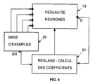
- Figure 4 illustrates the method of learning a neural network intended to be integrated in the device of figure 3.
- FIG. 5 represents a protection device according to a second embodiment, for a three-phase transformer.
- a differential protection device for a transformer T includes a processing circuit 5, a current sensor 3 for measuring the primary current It supplied to a primary winding 1 of the transformer by a power supply line L, a current sensor 4 for measuring a secondary current I2 leaving a winding secondary 2 of the transformer and a device 6 for interrupting the power supply of the transformer.
- the two current sensors 3 and 4 are connected to inputs of the processing circuit which provides a trip order 7 to the interrupt device 6 if certain trigger conditions are checked.
- the circuit of processing can also be connected to a fault signaling circuit 8.
- differential protection devices The most common faults detected by differential protection devices are: insulation or short-circuit faults between turns of the primary windings or secondary or between turns and transformer masses.
- Figure 2 shows a diagram of a faulty transformer.
- Current I1 crosses the primary winding 1 comprising a number of turns N1 and the current I2 is generated in the secondary winding 2 comprising a number of turns N2. Both windings are wound on a magnetic circuit 9.
- a fault of the primary winding is modeled by a resistive short circuit 10 between a turn and a winding end 1.
- Differential protection consists in detecting a differential current Id and in triggering the device if certain triggering conditions are verified.
- must be greater than a fraction K of the absolute value of the holding current
- the current differential is also compared to a threshold Im.
- are processed to keep only the fundamental component defined by the frequency of the current and the line voltage power supply, for example 50 Hz, or 60 Hz.
- trigger condition 3 is not sufficient to ensure correct operation of the device.
- the magnetic circuit can become saturated. This saturation causes the appearance of a transient differential current which can trigger the device when there is no fault.
- the various operating cases can be identified using a spectral analysis of the currents I1, I2 or the differential current Id.
- the overall treatment of the protection is not easy to obtain in a practical way with electronic circuits classic analog or digital.
- the protection device includes a sampling circuit 11 connected to the current sensors 3 and 4, a circuit preprocessing 12 connected to the sampling circuit 11 and a network 13 of neurons comprising four inputs E1, E2, E3, E4 connected to the preprocessing circuit.
- Output S of the neural network is connected to a relay 14 which causes the opening of the device 6.
- the output S can also be connected to a display device 15.
- the sampling circuit 11 samples with a sampling period Te, signals representative of the primary I1 and secondary I2 currents, and provides the samples to the preprocessing circuit 12.
- the samples of the signals of the currents I1 and I2 are used to calculate the differential current Id and the holding current Ir according to the expressions 1 and 2.
- Circuit 12 performs a spectral analysis of the signals according to a sliding window method. At each sampling period Te, a set of last samples collected during a period T1 corresponding to the duration of the window, is used for spectral analysis.
- the period T1 is equivalent to the period of the fundamental frequency of the current I1 supplied to the transformer, for example 50 or 60 Hz.
- the spectral analysis performed by the circuit 12 determines signals representative of the fundamental component H1D of the differential current, of the component of the second H2D harmonic (100 Hz or 120 Hz) of the differential current, of the component of the fifth harmonic H5D (250 Hz or 300 Hz) of the differential current and the fundamental component H1R of the holding current.
- the signals can, in a first embodiment, be applied to the inputs of the neural network.
- the input E1 then receives a signal representative of HD1, the input E2 a signal representative of HD2, input E3 a signal representative of H5D and input E4 a signal representative of H1R.
- the preprocessing circuit 12 then supplies on the input El a signal representative of the ratio H1D / H1R, on input E2 a signal representative of the H1D / In ratio, on input E3 a signal representative of the H2D / H1D ratio and on input E4 a signal representative of the H5D / H1D ratio.
- the neural network receives the input signals and determines the value of the output S as a function of situations learned during a learning phase. In actual operation the network must differentiate between healthy and faulty situations to give rise to a trigger.
- the neural network 13 of the multilayer perceptron type comprises three layers of neurons.
- a first layer 16 includes neurons connected to the inputs of the network 13.
- a second layer 17 constitutes an internal layer and a third layer 18 is connected to the output.
- the neurons of the second layer are connected to the neurons of the first and third layer.
- the network 16 has three neurons in the first layer, two neurons in the second layer and a neuron in the third layer.
- Each neuron has coefficients configured during a learning cycle where the main operating and fault situations are presented.
- Neural network output is defined for values located between -1 and 1. During learning, healthy situations are characterized by a output value around -0.8 and fault situations by values close to +0.8. In actual operation, positive values, from the output of the neural network, give a trigger order.
- FIG. 4 shows an automated learning of a network 13 of neurons that can be used in the differential protection device of Figure 3.
- a base of examples 20 includes all the situations that the network 13 must learn. For each situation, the base contains the values of the four signals applied to the inputs and the value of a corresponding reference SR output.
- the output S of the neural network and the reference output SR of the example base are connected to a regulating device 21 coefficients of neurons.
- the device 21 compares the two outputs and sets the coefficients so as to obtain a value of the output S of the network as close as possible of the value of the SR reference output. Examples base situations are used sequentially and / or simultaneously for learning the neural network.
- the examples are chosen so that the neural network can detect a fault situation within a maximum of 20 ms after the appearance of a fault.
- FIG. 3 given by way of example, is used with a transformer single phase or with the windings of a phase of a transformer polyphase.
- a device for differential protection is used for a three-phase transformer T3.
- Three sensors 3a, 3b, 3c of current measure primary currents I1a, I1b, I1c of three phases a, b and c supplying the three-phase primary winding 31.
- Three sensors 4a, 4b, 4c measure currents I2a, I2b, I2c leaving a three-phase secondary winding 32.
- the sensors current are connected to a sampling circuit 22.
- An output of circuit 22 is connected to a preprocessing circuit 23 which performs a spectral analysis and calculates the differential currents and holding currents.
- a neural network 24 includes inputs connected to circuit 23, an output S connected to a trigger relay 14 and auxiliary outputs S1, S2, S3, S4, S5 connected to a signaling circuit 25.
- the differential protection device described above can be applied to any type of electrical transformer whatever the primary voltages and currents or secondary as well as the coupling of primary or secondary windings.
- the power cut-off devices can be connected as well to the primary windings and to the secondary windings of the transformer.
- the pretreatment circuits 12 and 23 develop, in the above embodiments, signals representative of the holding current and the fundamental component, of Harmonic 2 and Harmonic 5 of the differential current, but other signals can also be used to supplement differential protection.
- neural networks 13 and 24 are not limited to those mentioned above, they can be adapted to particular uses depending on the transformer used.
- the sensors used by the above devices are current sensors only, but it is also possible to add other sensors to refine the protection.
- the devices can be supplemented by adding sensors to measure the primary and secondary voltages or pressure temperature measurement sensors or gas evolution inside the transformer.
- differential protection device can be done so independent as in the embodiments described above or be integrated and associated with other types of protection such as overload protection or external short circuit.
Landscapes
- Engineering & Computer Science (AREA)
- Power Engineering (AREA)
- Protection Of Transformers (AREA)
- Emergency Protection Circuit Devices (AREA)
Claims (5)
- Differenzstrom-Schutzeinrichtung eines Leistungstransformators mit ersten Meßmitteln (3; 3a, 3b, 3c) zur Messung eines über eine Primärwicklung (1; 31) des Transformators (T; T3) fließenden Stroms (I1, I1a, I1b, I1c), zweiten Meßmitteln (4; 4a, 4b, 4c) zur Messung des über eine Sekundärwicklung (2; 32) des Transformators (T; T3) fließenden Stroms (I2, I2a, I2b, I2c), an die Primärwicklung des Transformators angeschlossenen Unterbrechungsmitteln (6, 14) zur Unterbrechung der Einspeisung des Transformators sowie einer, an die ersten und zweiten Meßmittel angeschlossenen Verarbeitungsschaltung (11, 12, 13; 22, 23, 24), die ein Auslösesignal (S) an die Unterbrechungsmittel (6, 14) und/oder Informationssignale an Anzeige- bzw. Kontrollmittel (15; 25) liefert, wobei die Verarbeitungsschaltung an die ersten und zweiten Meßmittel angeschlossene Abtastmittel (11; 22) zur Abtastung von Signalen, welche die in der Primärwicklung und Sekundärwicklung gemessenen Ströme abbilden, sowie an die Abtastmittel (11; 22) angeschlossene Vorverarbeitungsmittel (12; 23) zur Lieferung von, die Grundschwingung (H1D), die zweite Harmonische (H2D) und die fünfte Harmonische (H5D) eines Differenzstroms abbildenden Signalen sowie eines, den Durchgangsstrom abbildenden Signals (H1R) umfaßt,
dadurch gekennzeichnet, daß die Verarbeitungsschaltung ein neuronales Netz (13; 24) mit an die Vorverarbeitungsmittel angeschlossenen Eingängen und mindestens einem Ausgang (S) zur Lieferung der Auslöse- und/oder Informationssignale umfaßt, wobei die Eingänge des neuronalen Netzes mit den von den Vorverarbeitungsmitteln gelieferten Signalen beaufschlagt werden, die die Grundschwingung (H1D), die zweite Harmonische (H2D) und die fünfte Harmonische (H5D) eines Differenzstroms sowie den Durchgangsstrom (H1R) abbilden. - Schutzeinrichtung nach Anspruch 1, dadurch gekennzeichnet, daß die Vorverarbeitungsmittel Signale an das neuronale Netz liefern, diedas Verhältnis (H1D/H1R) zwischen der Grundschwingung des Differenzstroms und der Grundschwingung des Durchgangsstroms,das Verhältnis (H1D/In) zwischen der Grundschwingung des Differenzstroms und dem Wert eines, einen Nennstrom (In) abbildenden Signals,das Verhältnis (H2D/H1D) zwischen der zweiten Harmonischen des Differenzstroms und der Grundschwingung des Differenzstroms sowiedas Verhältnis (H5D/H1D) zwischen der fünften Harmonischen des Differenzstroms und der Grundschwingung des Differenzstroms abbilden.
- Schutzeinrichtung nach einem der Ansprüche 1 und 2, dadurch gekennzeichnet, daß das neuronale Netz als Multilayer-Perceptron mit drei Neuronenschichten, vier Eingängen (E1, E2, E3, E4) pro zu überwachender Stromphase und einem Ausgang (S) für das Auslöse- und/oder Anzeigesignal ausgebildet ist, wobei die vier Eingänge an eine erste Schicht (16) mit drei Neuronen und der Ausgang an eine dritte Schicht (18) mit einem Neuron angeschlossen sind und eine zweite Schicht (17) mit zwei Neuronen an die erste und die dritte Schicht angeschlossen ist.
- Schutzeinrichtung nach irgendeinem der Ansprüche 1 bis 3, dadurch gekennzeichnet, daß die Neuronen des neuronalen Netzes während einer Lernphase errechnete Koeffizienten enthalten, wobei die Werte der die Eingänge des neuronales Netzes beaufschlagenden Signale interne Fehlersituationen, externe Fehlersituationen, Normalbetriebssituationen sowie Spannungsaufschaltungsituationen des Transformators abbilden.
- Schutzeinrichtung nach irgendeinem der Ansprüche 1 bis 4, dadurch gekennzeichnet, daß das neuronale Netz mindestens einen Anzeigeausgang zur Anzeige eines internen Fehlers zwischen einzelnen Windungen einer Wicklung des Transformators, eines internen Fehlers zwischen einer Windung einer Wicklung und Masse des Transformators und/oder eines externen Fehlers umfaßt.
Applications Claiming Priority (3)
| Application Number | Priority Date | Filing Date | Title |
|---|---|---|---|
| FR9400143A FR2714771B1 (fr) | 1994-01-06 | 1994-01-06 | Dispositif de protection différentielle d'un transformateur de puissance. |
| FR9400143 | 1994-01-06 | ||
| PCT/FR1994/001531 WO1995019059A1 (fr) | 1994-01-06 | 1994-12-26 | Dispositif de protection differentielle d'un transformateur de puissance |
Publications (2)
| Publication Number | Publication Date |
|---|---|
| EP0738432A1 EP0738432A1 (de) | 1996-10-23 |
| EP0738432B1 true EP0738432B1 (de) | 1998-11-11 |
Family
ID=9458857
Family Applications (1)
| Application Number | Title | Priority Date | Filing Date |
|---|---|---|---|
| EP95905167A Expired - Lifetime EP0738432B1 (de) | 1994-01-06 | 1994-12-26 | Differentialschutzeinrichtung für einen leistungstransformator |
Country Status (7)
| Country | Link |
|---|---|
| US (1) | US5784233A (de) |
| EP (1) | EP0738432B1 (de) |
| CN (1) | CN1047887C (de) |
| DE (1) | DE69414605T2 (de) |
| ES (1) | ES2127509T3 (de) |
| FR (1) | FR2714771B1 (de) |
| WO (1) | WO1995019059A1 (de) |
Families Citing this family (149)
| Publication number | Priority date | Publication date | Assignee | Title |
|---|---|---|---|---|
| IT1292453B1 (it) | 1997-07-02 | 1999-02-08 | Aeg Niederspannungstech Gmbh | Gruppo rotante di contatti per interrutttori di alta portata |
| CN1057646C (zh) * | 1997-10-15 | 2000-10-18 | 华中理工大学 | 变压器微机保护的虚拟三次谐波闭锁方法 |
| DE19819242B4 (de) | 1998-04-29 | 2005-11-10 | Ge Power Controls Polska Sp.Z.O.O. | Thermomagnetischer Leistungsschalter |
| US6114641A (en) | 1998-05-29 | 2000-09-05 | General Electric Company | Rotary contact assembly for high ampere-rated circuit breakers |
| US5959537A (en) * | 1998-07-09 | 1999-09-28 | Mcgraw-Edison Company | Variable trip fault indicator |
| US6247003B1 (en) * | 1998-08-13 | 2001-06-12 | Mcgraw-Edison Company | Current transformer saturation correction using artificial neural networks |
| US6087913A (en) | 1998-11-20 | 2000-07-11 | General Electric Company | Circuit breaker mechanism for a rotary contact system |
| US6037555A (en) | 1999-01-05 | 2000-03-14 | General Electric Company | Rotary contact circuit breaker venting arrangement including current transformer |
| US6166344A (en) | 1999-03-23 | 2000-12-26 | General Electric Company | Circuit breaker handle block |
| US6262872B1 (en) | 1999-06-03 | 2001-07-17 | General Electric Company | Electronic trip unit with user-adjustable sensitivity to current spikes |
| US6268991B1 (en) | 1999-06-25 | 2001-07-31 | General Electric Company | Method and arrangement for customizing electronic circuit interrupters |
| US6218917B1 (en) | 1999-07-02 | 2001-04-17 | General Electric Company | Method and arrangement for calibration of circuit breaker thermal trip unit |
| US6188036B1 (en) | 1999-08-03 | 2001-02-13 | General Electric Company | Bottom vented circuit breaker capable of top down assembly onto equipment |
| US6710988B1 (en) | 1999-08-17 | 2004-03-23 | General Electric Company | Small-sized industrial rated electric motor starter switch unit |
| US6252365B1 (en) | 1999-08-17 | 2001-06-26 | General Electric Company | Breaker/starter with auto-configurable trip unit |
| US6175288B1 (en) | 1999-08-27 | 2001-01-16 | General Electric Company | Supplemental trip unit for rotary circuit interrupters |
| US6396369B1 (en) | 1999-08-27 | 2002-05-28 | General Electric Company | Rotary contact assembly for high ampere-rated circuit breakers |
| US6232570B1 (en) | 1999-09-16 | 2001-05-15 | General Electric Company | Arcing contact arrangement |
| US6326869B1 (en) | 1999-09-23 | 2001-12-04 | General Electric Company | Clapper armature system for a circuit breaker |
| US6483680B1 (en) | 1999-10-13 | 2002-11-19 | General Electric Co. | Magnetizing inrush restraint method and relay for protection of power transformers |
| US6239395B1 (en) * | 1999-10-14 | 2001-05-29 | General Electric Company | Auxiliary position switch assembly for a circuit breaker |
| US6229413B1 (en) | 1999-10-19 | 2001-05-08 | General Electric Company | Support of stationary conductors for a circuit breaker |
| US6317018B1 (en) | 1999-10-26 | 2001-11-13 | General Electric Company | Circuit breaker mechanism |
| US6232856B1 (en) | 1999-11-02 | 2001-05-15 | General Electric Company | Magnetic shunt assembly |
| US6377144B1 (en) | 1999-11-03 | 2002-04-23 | General Electric Company | Molded case circuit breaker base and mid-cover assembly |
| ES2249875T3 (es) | 1999-11-03 | 2006-04-01 | AEG NIEDERSPANNUNGSTECHNIK GMBH & CO. KG | Disposicion de brazo de contacto rotatorio para disyuntor. |
| US6356421B1 (en) * | 1999-11-29 | 2002-03-12 | Schweitzer Engineering Labs., Inc. | System for power transformer differential protection |
| US6300586B1 (en) | 1999-12-09 | 2001-10-09 | General Electric Company | Arc runner retaining feature |
| US6310307B1 (en) | 1999-12-17 | 2001-10-30 | General Electric Company | Circuit breaker rotary contact arm arrangement |
| US6184761B1 (en) | 1999-12-20 | 2001-02-06 | General Electric Company | Circuit breaker rotary contact arrangement |
| US6172584B1 (en) | 1999-12-20 | 2001-01-09 | General Electric Company | Circuit breaker accessory reset system |
| US6215379B1 (en) | 1999-12-23 | 2001-04-10 | General Electric Company | Shunt for indirectly heated bimetallic strip |
| US6281461B1 (en) | 1999-12-27 | 2001-08-28 | General Electric Company | Circuit breaker rotor assembly having arc prevention structure |
| US6346869B1 (en) | 1999-12-28 | 2002-02-12 | General Electric Company | Rating plug for circuit breakers |
| US6211758B1 (en) | 2000-01-11 | 2001-04-03 | General Electric Company | Circuit breaker accessory gap control mechanism |
| US6239677B1 (en) | 2000-02-10 | 2001-05-29 | General Electric Company | Circuit breaker thermal magnetic trip unit |
| US6429759B1 (en) | 2000-02-14 | 2002-08-06 | General Electric Company | Split and angled contacts |
| US6281458B1 (en) | 2000-02-24 | 2001-08-28 | General Electric Company | Circuit breaker auxiliary magnetic trip unit with pressure sensitive release |
| US6313425B1 (en) | 2000-02-24 | 2001-11-06 | General Electric Company | Cassette assembly with rejection features |
| US6204743B1 (en) | 2000-02-29 | 2001-03-20 | General Electric Company | Dual connector strap for a rotary contact circuit breaker |
| US6404314B1 (en) | 2000-02-29 | 2002-06-11 | General Electric Company | Adjustable trip solenoid |
| US6448521B1 (en) | 2000-03-01 | 2002-09-10 | General Electric Company | Blocking apparatus for circuit breaker contact structure |
| US6379196B1 (en) | 2000-03-01 | 2002-04-30 | General Electric Company | Terminal connector for a circuit breaker |
| US6346868B1 (en) | 2000-03-01 | 2002-02-12 | General Electric Company | Circuit interrupter operating mechanism |
| US6340925B1 (en) | 2000-03-01 | 2002-01-22 | General Electric Company | Circuit breaker mechanism tripping cam |
| JP3389914B2 (ja) * | 2000-03-03 | 2003-03-24 | 日本電気株式会社 | 集積回路の電源電流値のサンプリング方法及び装置、及びその制御プログラムを記録した記憶媒体 |
| US6459349B1 (en) | 2000-03-06 | 2002-10-01 | General Electric Company | Circuit breaker comprising a current transformer with a partial air gap |
| US6211757B1 (en) | 2000-03-06 | 2001-04-03 | General Electric Company | Fast acting high force trip actuator |
| US6366438B1 (en) | 2000-03-06 | 2002-04-02 | General Electric Company | Circuit interrupter rotary contact arm |
| US6496347B1 (en) | 2000-03-08 | 2002-12-17 | General Electric Company | System and method for optimization of a circuit breaker mechanism |
| US6429659B1 (en) | 2000-03-09 | 2002-08-06 | General Electric Company | Connection tester for an electronic trip unit |
| US6366188B1 (en) | 2000-03-15 | 2002-04-02 | General Electric Company | Accessory and recess identification system for circuit breakers |
| US6218919B1 (en) | 2000-03-15 | 2001-04-17 | General Electric Company | Circuit breaker latch mechanism with decreased trip time |
| US6232859B1 (en) | 2000-03-15 | 2001-05-15 | General Electric Company | Auxiliary switch mounting configuration for use in a molded case circuit breaker |
| US6421217B1 (en) | 2000-03-16 | 2002-07-16 | General Electric Company | Circuit breaker accessory reset system |
| US6459059B1 (en) | 2000-03-16 | 2002-10-01 | General Electric Company | Return spring for a circuit interrupter operating mechanism |
| US6479774B1 (en) | 2000-03-17 | 2002-11-12 | General Electric Company | High energy closing mechanism for circuit breakers |
| US6373010B1 (en) | 2000-03-17 | 2002-04-16 | General Electric Company | Adjustable energy storage mechanism for a circuit breaker motor operator |
| US6586693B2 (en) | 2000-03-17 | 2003-07-01 | General Electric Company | Self compensating latch arrangement |
| US6476698B1 (en) | 2000-03-17 | 2002-11-05 | General Electric Company | Convertible locking arrangement on breakers |
| FR2806548B1 (fr) | 2000-03-17 | 2002-08-23 | Ge Power Controls France | Mecanisme extractible pour disjoncteurs |
| US6639168B1 (en) | 2000-03-17 | 2003-10-28 | General Electric Company | Energy absorbing contact arm stop |
| US6472620B2 (en) | 2000-03-17 | 2002-10-29 | Ge Power Controls France Sas | Locking arrangement for circuit breaker draw-out mechanism |
| US6388213B1 (en) | 2000-03-17 | 2002-05-14 | General Electric Company | Locking device for molded case circuit breakers |
| US6559743B2 (en) | 2000-03-17 | 2003-05-06 | General Electric Company | Stored energy system for breaker operating mechanism |
| US6747535B2 (en) | 2000-03-27 | 2004-06-08 | General Electric Company | Precision location system between actuator accessory and mechanism |
| US6373357B1 (en) | 2000-05-16 | 2002-04-16 | General Electric Company | Pressure sensitive trip mechanism for a rotary breaker |
| US6995640B2 (en) | 2000-05-16 | 2006-02-07 | General Electric Company | Pressure sensitive trip mechanism for circuit breakers |
| US6400245B1 (en) | 2000-10-13 | 2002-06-04 | General Electric Company | Draw out interlock for circuit breakers |
| US6429760B1 (en) | 2000-10-19 | 2002-08-06 | General Electric Company | Cross bar for a conductor in a rotary breaker |
| US6806800B1 (en) | 2000-10-19 | 2004-10-19 | General Electric Company | Assembly for mounting a motor operator on a circuit breaker |
| US6531941B1 (en) | 2000-10-19 | 2003-03-11 | General Electric Company | Clip for a conductor in a rotary breaker |
| US6362711B1 (en) | 2000-11-10 | 2002-03-26 | General Electric Company | Circuit breaker cover with screw locating feature |
| US6380829B1 (en) | 2000-11-21 | 2002-04-30 | General Electric Company | Motor operator interlock and method for circuit breakers |
| US6448522B1 (en) | 2001-01-30 | 2002-09-10 | General Electric Company | Compact high speed motor operator for a circuit breaker |
| US6476337B2 (en) | 2001-02-26 | 2002-11-05 | General Electric Company | Auxiliary switch actuation arrangement |
| US6882258B2 (en) | 2001-02-27 | 2005-04-19 | General Electric Company | Mechanical bell alarm assembly for a circuit breaker |
| US6507184B1 (en) | 2001-03-28 | 2003-01-14 | Abb Automation Inc. | Methods and apparatus for differential current measurement in a three-phase power system |
| US6958894B2 (en) * | 2001-05-17 | 2005-10-25 | Yong Cheol Kang | Relaying method for protecting a transformer using a difference of current |
| US6678135B2 (en) | 2001-09-12 | 2004-01-13 | General Electric Company | Module plug for an electronic trip unit |
| US6469882B1 (en) | 2001-10-31 | 2002-10-22 | General Electric Company | Current transformer initial condition correction |
| US6804101B2 (en) | 2001-11-06 | 2004-10-12 | General Electric Company | Digital rating plug for electronic trip unit in circuit breakers |
| SE0303615D0 (sv) * | 2003-12-31 | 2003-12-31 | Abb Ab | Method and device for Fault Detection in Transformers |
| CN100350694C (zh) * | 2004-02-13 | 2007-11-21 | 浙江大学 | 防止变压器差动保护误动的综合差流制动装置 |
| CN100413168C (zh) * | 2004-02-13 | 2008-08-20 | 浙江大学 | 防止变压器差动保护误动的综合差流方法 |
| CN100413169C (zh) * | 2004-02-13 | 2008-08-20 | 浙江大学 | 防止多分支变压器差动保护误动的分相零序制动方法 |
| CN100394657C (zh) * | 2004-02-13 | 2008-06-11 | 浙江大学 | 防止多分支变压器差动保护误动的分相制动装置 |
| CN100433488C (zh) * | 2004-02-13 | 2008-11-12 | 浙江大学 | 一种防止多分支变压器差动保护误动的相序合成制动方法 |
| CN100350702C (zh) * | 2004-02-13 | 2007-11-21 | 浙江大学 | 防止变压器保护误动的故障分量相序综合零序制动方法 |
| CN100413165C (zh) * | 2004-02-13 | 2008-08-20 | 浙江大学 | 利用故障分量防止变压器差动保护误动的分相制动装置 |
| CN100388580C (zh) * | 2004-02-13 | 2008-05-14 | 浙江大学 | 防止多分支变压器差动保护误动的三相综合制动装置 |
| CN100413167C (zh) * | 2004-02-13 | 2008-08-20 | 浙江大学 | 利用故障分量防止多分支变压器差动保护误动的最大差流综合制动装置 |
| CN100388581C (zh) * | 2004-02-13 | 2008-05-14 | 浙江大学 | 防止变压器差动保护误动的分相差流方法 |
| CN100409524C (zh) * | 2004-02-13 | 2008-08-06 | 浙江大学 | 利用故障分量防止多分支变压器差动保护误动的三相制动装置 |
| CN100433487C (zh) * | 2004-02-13 | 2008-11-12 | 浙江大学 | 防止多分支变压器差动保护误动的分相综合制动装置 |
| CN100413166C (zh) * | 2004-02-13 | 2008-08-20 | 浙江大学 | 防止多分支变压器差动保护误动的最大差流综合制动装置 |
| CN100409523C (zh) * | 2004-02-13 | 2008-08-06 | 浙江大学 | 防止多分支变压器差动保护误动的三相制动装置 |
| CN100407534C (zh) * | 2004-02-13 | 2008-07-30 | 浙江大学 | 防止变压器差动保护误动的三相制动装置 |
| CN100350698C (zh) * | 2004-02-13 | 2007-11-21 | 浙江大学 | 防止变压器保护误动的故障分量正序合成制动装置 |
| CN100350703C (zh) * | 2004-02-13 | 2007-11-21 | 浙江大学 | 防止变压器差动保护误动的零序故障分量分相制动方法 |
| CN100407536C (zh) * | 2004-02-13 | 2008-07-30 | 浙江大学 | 防止变压器保护误动的故障分量最大零序制动方法 |
| CN100350701C (zh) * | 2004-02-13 | 2007-11-21 | 浙江大学 | 利用故障分量防止变压器差动保护误动的综合差流方法 |
| CN100367606C (zh) * | 2004-12-02 | 2008-02-06 | 浙江大学 | 带多侧零序电流比率制动的变压器纵差保护方法 |
| CN100367603C (zh) * | 2004-12-02 | 2008-02-06 | 浙江大学 | 防止变压器保护误动的最大变换电流零序制动方法 |
| CN100367614C (zh) * | 2004-12-02 | 2008-02-06 | 浙江大学 | 一种带最大侧零序比率制动的变压器纵差保护元件 |
| CN100367605C (zh) * | 2004-12-02 | 2008-02-06 | 浙江大学 | 带最大零序电流比率制动的变压器纵差保护方法 |
| CN100350704C (zh) * | 2004-12-02 | 2007-11-21 | 浙江大学 | 一种防止变压器保护误动的相间与零序制动方法 |
| CN100367611C (zh) * | 2004-12-02 | 2008-02-06 | 浙江大学 | 带最大零序电流故障分量比率制动的变压器纵差保护方法 |
| CN100367609C (zh) * | 2004-12-02 | 2008-02-06 | 浙江大学 | 带多侧零序电流比率制动的变压器纵差保护元件 |
| CN100388582C (zh) * | 2004-12-02 | 2008-05-14 | 浙江大学 | 防止变压器保护误动的正序与零序制动方法 |
| CN100367608C (zh) * | 2004-12-02 | 2008-02-06 | 浙江大学 | 带最大零序电流比率制动的变压器纵差保护元件 |
| CN100367607C (zh) * | 2004-12-02 | 2008-02-06 | 浙江大学 | 带零序电流比率制动的变压器纵差保护元件 |
| CN100409528C (zh) * | 2004-12-02 | 2008-08-06 | 浙江大学 | 防止变压器保护误动的相间与零序故障分量制动方法 |
| CN100367604C (zh) * | 2004-12-02 | 2008-02-06 | 浙江大学 | 带零序比率制动的变压器纵差保护方法 |
| CN100388583C (zh) * | 2004-12-02 | 2008-05-14 | 浙江大学 | 防止变压器保护误动的变换分相零序故障分量制动方法 |
| CN100394655C (zh) * | 2004-12-02 | 2008-06-11 | 浙江大学 | 防止变压器保护误动的最大电流零序故障分量制动方法 |
| CN100394656C (zh) * | 2004-12-02 | 2008-06-11 | 浙江大学 | 防止变压器保护误动的最大相间与零序故障分量制动方法 |
| CN100367602C (zh) * | 2004-12-02 | 2008-02-06 | 浙江大学 | 一种防止变压器保护误动的变换分相零序制动方法 |
| CN100367615C (zh) * | 2004-12-02 | 2008-02-06 | 浙江大学 | 一种带多侧零序比率制动的变压器纵差保护元件 |
| CN100367610C (zh) * | 2004-12-02 | 2008-02-06 | 浙江大学 | 带零序电流故障分量比率制动的变压器纵差保护方法 |
| EP1929602B1 (de) * | 2005-08-30 | 2011-10-12 | ABB Technology AG | Verfahren und system zur fehlererkennung in elektrischen leistungsgeräten |
| ES2339387T3 (es) * | 2005-12-09 | 2010-05-19 | Abb Technology Ltd | Metodo y dispositivo para deteccion de fallos en un transformador de potencia trifasico de n devanados. |
| CN101119022B (zh) * | 2006-08-02 | 2010-06-16 | 贵阳铝镁设计研究院 | 整流变压器组横联差动电流保护方法及装置 |
| US7609158B2 (en) * | 2006-10-26 | 2009-10-27 | Cooper Technologies Company | Electrical power system control communications network |
| CN100449900C (zh) * | 2006-11-22 | 2009-01-07 | 北京四方继保自动化股份有限公司 | 高压交流可控型并联电抗器大差动保护方法 |
| US7715002B2 (en) * | 2007-01-23 | 2010-05-11 | Bionorica Ag | Method for classifying scientific materials such as silicate materials, polymer materials and/or nanomaterials |
| WO2009048972A1 (en) * | 2007-10-09 | 2009-04-16 | Schweitzer Engineering Laboratories, Inc. | Transformer through-fault current monitor |
| US9383394B2 (en) * | 2007-11-02 | 2016-07-05 | Cooper Technologies Company | Overhead communicating device |
| US8067946B2 (en) * | 2007-11-02 | 2011-11-29 | Cooper Technologies Company | Method for repairing a transmission line in an electrical power distribution system |
| US7930141B2 (en) | 2007-11-02 | 2011-04-19 | Cooper Technologies Company | Communicating faulted circuit indicator apparatus and method of use thereof |
| US8594956B2 (en) * | 2007-11-02 | 2013-11-26 | Cooper Technologies Company | Power line energy harvesting power supply |
| US7903381B2 (en) * | 2008-03-11 | 2011-03-08 | Schweitzer Engineering Laboratories, Inc. | Negative sequence differential element |
| US20090231764A1 (en) * | 2008-03-14 | 2009-09-17 | Cooper Technologies Company | Capacitor Bank Monitor and Method of use Thereof |
| US8072225B2 (en) * | 2008-10-08 | 2011-12-06 | Hamilton Sundstrand Corporation | Differential power detection |
| CA2978772C (en) | 2010-08-10 | 2019-09-03 | Cooper Technologies Company | Apparatus for mounting an overhead monitoring device |
| US8717725B2 (en) | 2010-12-02 | 2014-05-06 | Schweitzer Engineering Laboratories Inc | Dual-comparator restricted earth fault protection |
| CN102074940A (zh) * | 2010-12-09 | 2011-05-25 | 山东省电力学校 | 一种直流系统线路电流差动保护方法 |
| CN102087311B (zh) * | 2010-12-21 | 2013-03-06 | 彭浩明 | 一种提高电力互感器测量精度的方法 |
| KR20120087013A (ko) * | 2011-01-27 | 2012-08-06 | 엘에스산전 주식회사 | 변압기 보호 계전기, 보호 방법, 및 이를 포함한 변압기 보호 시스템 |
| WO2012155974A1 (de) * | 2011-05-19 | 2012-11-22 | Siemens Aktiengesellschaft | Verfahren zum erzeugen eines fehlersignals |
| JP5713848B2 (ja) * | 2011-09-14 | 2015-05-07 | 株式会社東芝 | 励磁突入電流抑制装置 |
| US9379556B2 (en) | 2013-03-14 | 2016-06-28 | Cooper Technologies Company | Systems and methods for energy harvesting and current and voltage measurements |
| FR3039722B1 (fr) * | 2015-07-27 | 2017-09-15 | Schneider Electric Ind Sas | Systeme de surveillance d'un poste de transformation |
| CN106532653B (zh) * | 2016-10-14 | 2018-09-18 | 国网山东省电力公司泰安供电公司 | 一种差动保护装置及其方法 |
| EP3921908B1 (de) * | 2019-02-04 | 2025-12-10 | S&C Electric Company | Fehlerschutzanordnung für einen rücksetzbaren transformatorschutz |
| EP3699606B1 (de) * | 2019-02-22 | 2025-12-24 | ABB Schweiz AG | Schutzschaltung für einen mittelspannungs- oder hochspannungstransformator |
| DE102020119068A1 (de) * | 2020-07-20 | 2022-01-20 | E.ON Digital Technology GmbH | Verfahren zur vernetzten Überwachung von wenigstens einem Transformator |
| DE102020119067A1 (de) * | 2020-07-20 | 2022-01-20 | E.ON Digital Technology GmbH | Verfahren zur vernetzten Überwachung von wenigstens einem Objekt |
| EP4012864B1 (de) * | 2020-12-09 | 2023-11-01 | Siemens Aktiengesellschaft | Schutzeinrichtung und verfahren zum überwachen eines elektrischen energieversorgungsnetzes |
Family Cites Families (3)
| Publication number | Priority date | Publication date | Assignee | Title |
|---|---|---|---|---|
| US5014153A (en) * | 1989-02-01 | 1991-05-07 | Basler Electric Company | Transformer differential relay |
| US5627712A (en) * | 1990-04-19 | 1997-05-06 | General Electric Company | Transformer differential relay |
| US5629870A (en) * | 1994-05-31 | 1997-05-13 | Siemens Energy & Automation, Inc. | Method and apparatus for predicting electric induction machine failure during operation |
-
1994
- 1994-01-06 FR FR9400143A patent/FR2714771B1/fr not_active Expired - Fee Related
- 1994-12-26 WO PCT/FR1994/001531 patent/WO1995019059A1/fr not_active Ceased
- 1994-12-26 ES ES95905167T patent/ES2127509T3/es not_active Expired - Lifetime
- 1994-12-26 US US08/663,104 patent/US5784233A/en not_active Expired - Lifetime
- 1994-12-26 EP EP95905167A patent/EP0738432B1/de not_active Expired - Lifetime
- 1994-12-26 CN CN94194784A patent/CN1047887C/zh not_active Expired - Fee Related
- 1994-12-26 DE DE69414605T patent/DE69414605T2/de not_active Expired - Lifetime
Also Published As
| Publication number | Publication date |
|---|---|
| FR2714771B1 (fr) | 1996-02-02 |
| CN1047887C (zh) | 1999-12-29 |
| FR2714771A1 (fr) | 1995-07-07 |
| ES2127509T3 (es) | 1999-04-16 |
| CN1141097A (zh) | 1997-01-22 |
| DE69414605T2 (de) | 1999-06-17 |
| US5784233A (en) | 1998-07-21 |
| EP0738432A1 (de) | 1996-10-23 |
| WO1995019059A1 (fr) | 1995-07-13 |
| DE69414605D1 (de) | 1998-12-17 |
Similar Documents
| Publication | Publication Date | Title |
|---|---|---|
| WO1995019059A1 (fr) | Dispositif de protection differentielle d'un transformateur de puissance | |
| EP0407310B1 (de) | Festkörperauslöser mit einer Desensibilisierungsvorrichtung für den Erdschutz | |
| EP0396477B1 (de) | Statischer Auslöser für einen ein dreiphasiges Netz schützenden Schutzschalter, der die Bestimmung des Fehlertyps erlaubt | |
| EP2687860B1 (de) | Richtungs-Erkennung eines empfindlichen Mittelspannungs-Erdschlusses durch lineare Korrelation | |
| US5172329A (en) | Microprocessor-based digital protective relay for power transformers | |
| EP1736784B1 (de) | Gerät zur Fehlerstrommessung, Auslösemodul und Schaltvorrichtung | |
| EP0603088B1 (de) | Vorrichtung zur numerischen Berechnung einer symmetrischen Komponente einer elektrischen Grösse eines Dreiphasennetzes und damit versehenes Relais | |
| EP2849195B1 (de) | Zusatzvorrichung für elektrischen Schutzschalter, elektrisches System mit einem Schutzschalter und dieser Zusatzvorrichtung und Verfahren zur Bestimmung des Grunds der Öffnung des Schutzshalters dank dieser Zusatzvorrichtung | |
| FR2649554A1 (fr) | Disjoncteur electronique utilisant un circuit numerique qui presente une possibilite de declenchement instantane | |
| EP3106887B1 (de) | Verfahren und vorrichtung zur detektion einer störung in einem stromnetz | |
| EP0041202A1 (de) | Wiedereinschaltvorrichtung für Übertragungsleitung | |
| US5170308A (en) | Method and system of transformer protection and method and system of detecting a defective winding | |
| EP0859443A1 (de) | Schützrelais und Verfahren | |
| EP2927928B1 (de) | Verfahren zur bestimmung einer überhitzung mindestens einer verbindungsklemme einer elektrischen vorrichtung, entsprechendes hilfsgerät und elektrisches system, das eine solche elektrische vorrichtung und ein solches hilfsgerät umfasst | |
| EP0592337B2 (de) | Elektronischer Auslöser mit Erdschutz | |
| FR2690573A1 (fr) | Dispositif de contrôle de défaut homopolaire dans un réseau de distribution électrique. | |
| EP0605335B1 (de) | Elektronischer Auslöser mit Testgerät | |
| FR3101428A1 (fr) | Disjoncteur et appareil mobile | |
| EP2910958A1 (de) | Störungserkennung, insbesondere einer vorübergehenden Störung, in einem Stromnetz | |
| EP0537066A1 (de) | Verfahren zur selektiven Detektion von Widerstandsdefekten in Stromverteilungsnetzwerken und Gerät zur Ausführung des Verfahrens | |
| EP1045500B1 (de) | Elektronischer Auslöser mit Phasewiederherstellung und Lastschalter mit einem solchen Auslöser versehen | |
| EP4241353A1 (de) | Vorrichtungen zur überwachung und zum schutz von stromkreisen | |
| EP3029477B1 (de) | Vorrichtung und verfahren zur zustandsüberwachung eines schutz- oder versorgungsschaltkreises in einem netz oder einem stromverteilungsschaltkreis, und entsprechendes verteilungsnetz und entsprechender verteilungsschaltkreis | |
| EP4492598B1 (de) | Verfahren zur überprüfung der eignung für restströme von differentialschutzschaltern | |
| US12249948B2 (en) | Split-phase protection of generators |
Legal Events
| Date | Code | Title | Description |
|---|---|---|---|
| PUAI | Public reference made under article 153(3) epc to a published international application that has entered the european phase |
Free format text: ORIGINAL CODE: 0009012 |
|
| 17P | Request for examination filed |
Effective date: 19960619 |
|
| AK | Designated contracting states |
Kind code of ref document: A1 Designated state(s): DE ES GB IT SE |
|
| GRAG | Despatch of communication of intention to grant |
Free format text: ORIGINAL CODE: EPIDOS AGRA |
|
| 17Q | First examination report despatched |
Effective date: 19980127 |
|
| RBV | Designated contracting states (corrected) |
Designated state(s): DE ES GB IT SE |
|
| GRAG | Despatch of communication of intention to grant |
Free format text: ORIGINAL CODE: EPIDOS AGRA |
|
| GRAH | Despatch of communication of intention to grant a patent |
Free format text: ORIGINAL CODE: EPIDOS IGRA |
|
| GRAH | Despatch of communication of intention to grant a patent |
Free format text: ORIGINAL CODE: EPIDOS IGRA |
|
| GRAA | (expected) grant |
Free format text: ORIGINAL CODE: 0009210 |
|
| AK | Designated contracting states |
Kind code of ref document: B1 Designated state(s): DE ES GB IT SE |
|
| REF | Corresponds to: |
Ref document number: 69414605 Country of ref document: DE Date of ref document: 19981217 |
|
| GBT | Gb: translation of ep patent filed (gb section 77(6)(a)/1977) |
Effective date: 19990113 |
|
| ITF | It: translation for a ep patent filed | ||
| REG | Reference to a national code |
Ref country code: ES Ref legal event code: FG2A Ref document number: 2127509 Country of ref document: ES Kind code of ref document: T3 |
|
| PLBE | No opposition filed within time limit |
Free format text: ORIGINAL CODE: 0009261 |
|
| STAA | Information on the status of an ep patent application or granted ep patent |
Free format text: STATUS: NO OPPOSITION FILED WITHIN TIME LIMIT |
|
| 26N | No opposition filed | ||
| REG | Reference to a national code |
Ref country code: GB Ref legal event code: IF02 |
|
| PGFP | Annual fee paid to national office [announced via postgrant information from national office to epo] |
Ref country code: ES Payment date: 20030121 Year of fee payment: 9 |
|
| PG25 | Lapsed in a contracting state [announced via postgrant information from national office to epo] |
Ref country code: ES Free format text: LAPSE BECAUSE OF NON-PAYMENT OF DUE FEES Effective date: 20031227 |
|
| REG | Reference to a national code |
Ref country code: ES Ref legal event code: FD2A Effective date: 20031227 |
|
| PGFP | Annual fee paid to national office [announced via postgrant information from national office to epo] |
Ref country code: GB Payment date: 20101222 Year of fee payment: 17 |
|
| PGFP | Annual fee paid to national office [announced via postgrant information from national office to epo] |
Ref country code: DE Payment date: 20101218 Year of fee payment: 17 |
|
| PGFP | Annual fee paid to national office [announced via postgrant information from national office to epo] |
Ref country code: SE Payment date: 20111213 Year of fee payment: 18 |
|
| REG | Reference to a national code |
Ref country code: DE Ref legal event code: R084 Ref document number: 69414605 Country of ref document: DE Effective date: 20111228 |
|
| PGFP | Annual fee paid to national office [announced via postgrant information from national office to epo] |
Ref country code: IT Payment date: 20111228 Year of fee payment: 18 |
|
| PG25 | Lapsed in a contracting state [announced via postgrant information from national office to epo] |
Ref country code: SE Free format text: LAPSE BECAUSE OF NON-PAYMENT OF DUE FEES Effective date: 20121227 |
|
| GBPC | Gb: european patent ceased through non-payment of renewal fee |
Effective date: 20121226 |
|
| REG | Reference to a national code |
Ref country code: DE Ref legal event code: R119 Ref document number: 69414605 Country of ref document: DE Effective date: 20130702 |
|
| PG25 | Lapsed in a contracting state [announced via postgrant information from national office to epo] |
Ref country code: DE Free format text: LAPSE BECAUSE OF NON-PAYMENT OF DUE FEES Effective date: 20130702 |
|
| PG25 | Lapsed in a contracting state [announced via postgrant information from national office to epo] |
Ref country code: GB Free format text: LAPSE BECAUSE OF NON-PAYMENT OF DUE FEES Effective date: 20121226 |
|
| PG25 | Lapsed in a contracting state [announced via postgrant information from national office to epo] |
Ref country code: IT Free format text: LAPSE BECAUSE OF NON-PAYMENT OF DUE FEES Effective date: 20121226 |