EP0738572B1 - Verfahren zur Orientierung von Einkristallen zum Schneiden in eine Schneidemaschine und Einrichtung zur Durchführung des Verfahrens - Google Patents
Verfahren zur Orientierung von Einkristallen zum Schneiden in eine Schneidemaschine und Einrichtung zur Durchführung des Verfahrens Download PDFInfo
- Publication number
- EP0738572B1 EP0738572B1 EP96105699A EP96105699A EP0738572B1 EP 0738572 B1 EP0738572 B1 EP 0738572B1 EP 96105699 A EP96105699 A EP 96105699A EP 96105699 A EP96105699 A EP 96105699A EP 0738572 B1 EP0738572 B1 EP 0738572B1
- Authority
- EP
- European Patent Office
- Prior art keywords
- single crystal
- cutting
- plane
- support
- geometric
- Prior art date
- Legal status (The legal status is an assumption and is not a legal conclusion. Google has not performed a legal analysis and makes no representation as to the accuracy of the status listed.)
- Expired - Lifetime
Links
- 238000005520 cutting process Methods 0.000 title claims description 137
- 238000000034 method Methods 0.000 title claims description 25
- 239000013078 crystal Substances 0.000 claims description 153
- 238000005259 measurement Methods 0.000 claims description 9
- 238000004519 manufacturing process Methods 0.000 description 4
- 230000003287 optical effect Effects 0.000 description 4
- 238000010586 diagram Methods 0.000 description 2
- 239000011159 matrix material Substances 0.000 description 2
- 239000004065 semiconductor Substances 0.000 description 2
- 101100008046 Caenorhabditis elegans cut-2 gene Proteins 0.000 description 1
- XUIMIQQOPSSXEZ-UHFFFAOYSA-N Silicon Chemical compound [Si] XUIMIQQOPSSXEZ-UHFFFAOYSA-N 0.000 description 1
- 238000004026 adhesive bonding Methods 0.000 description 1
- 238000010276 construction Methods 0.000 description 1
- 238000012937 correction Methods 0.000 description 1
- 230000001419 dependent effect Effects 0.000 description 1
- 230000001627 detrimental effect Effects 0.000 description 1
- 230000002349 favourable effect Effects 0.000 description 1
- 238000012986 modification Methods 0.000 description 1
- 230000004048 modification Effects 0.000 description 1
- 210000000056 organ Anatomy 0.000 description 1
- 230000001105 regulatory effect Effects 0.000 description 1
- 229910052710 silicon Inorganic materials 0.000 description 1
- 239000010703 silicon Substances 0.000 description 1
- 238000012546 transfer Methods 0.000 description 1
- 235000012431 wafers Nutrition 0.000 description 1
Images

Classifications
-
- B—PERFORMING OPERATIONS; TRANSPORTING
- B28—WORKING CEMENT, CLAY, OR STONE
- B28D—WORKING STONE OR STONE-LIKE MATERIALS
- B28D5/00—Fine working of gems, jewels, crystals, e.g. of semiconductor material; apparatus or devices therefor
- B28D5/0058—Accessories specially adapted for use with machines for fine working of gems, jewels, crystals, e.g. of semiconductor material
- B28D5/0082—Accessories specially adapted for use with machines for fine working of gems, jewels, crystals, e.g. of semiconductor material for supporting, holding, feeding, conveying or discharging work
- B28D5/0088—Accessories specially adapted for use with machines for fine working of gems, jewels, crystals, e.g. of semiconductor material for supporting, holding, feeding, conveying or discharging work the supporting or holding device being angularly adjustable
Definitions
- the present invention relates to a method for the orientation of a single crystal for cutting in a cutting machine according to a cutting plan predetermined, according to which the single crystal is oriented by means of a positioning device outside the machine cutting according to a predetermined orientation with respect to a cutting support, the single crystal is fixed in accordance at said predetermined orientation on the cutting support whose placement in the cutting machine is geometrically defined with respect to a cutting plane perpendicular to a work plane of the machine cutting, and we have the cutting support after fixing of the single crystal in the cutting machine according to said geometrically defined positioning.
- Monocrystals generally for optical uses or semiconductors require that they be cut according to very precise orientations in relation to the axes of the crystal lattice.
- their manufacture does not allow perfectly control the orientation of the axes of the network crystalline with respect to the geometric axes. It is therefore necessary to that the cut is correct correct on the one hand the error of manufacturing and secondly take into account the angles formed between the cutting plane and the crystalline plane chosen or imposed by the subsequent uses or processes. Since the cutting is done from a geometric single crystal, it will position and hold it in space so that the movement of the cutting system is parallel to the plane desired cutting. There are endless possible positions, however there are only four that additionally place the single crystal in a plane perpendicular to the cutting plane of the machine. The positioning of single crystals according to one of these four positions therefore makes it possible to cut not only in the desired orientation but also minimize the cutting time therefore improve the productivity of the cutting device.
- Single crystal orientation devices are already known and used in the semiconductor industry on internal diameter chainsaws or wire saws.
- the positioning is done using an adjustable table y '' ', z' '' mounted directly on the machine. Adjustment is done after measurement optical or x-ray. The correction is then introduced according to y '' ', z' ''.
- This way of practicing has the disadvantage on the one hand to have an inclined position of the single crystal with respect to advance of the cutting element, which is very unfavorable in the case of a wire saw where the wire ply must be parallel to the geometric single crystal, and secondly not to minimize the cutting length, which is then unfavorable for internal diameter saws by reducing their productivity.
- this way of practicing requires regulating the machine table before each cut very precise and in an often dirty industrial environment therefore not very favorable for this type of operation. The setting time of the machine also contributes to lower productivity.
- Document DE-A-27 52 925 describes a device orientation of single crystals with a frame on which is mounted a geometric head allowing movements of rotation around three perpendicular axes of the single crystal fixed on this geometric head and the approximation of the single crystal and a cutting support on which this single crystal will be fixed.
- the device described in this document allows the orientation of a single crystal outside the machine cutting, however, it does not reveal how the orientation process should be carried out to avoid inclined position of the single crystal with respect to the direction of the advancement of the cutting elements of the machine.
- the object of the present invention is to remedy the disadvantages mentioned above and it is characterized for this purpose in that that said predetermined orientation is obtained by disposing the single crystal on the positioning device so that a of its geometric axes of the geometric shape of the single crystal is included in a reference plane corresponding to the cutting machine work plan, by rotating the single crystal by a first angle predetermined d around said geometric axis to bring the normal to the cutting plane of the single crystal in said plane of reference, and by performing a relative rotation between the support and the single crystal of a second angle predetermined around an axis perpendicular to said plane of reference so that the normal to the cutting plane is oriented in a reference direction corresponding to the normal to the cutting plane of the machine, said axis geometric and normal to the cutting plane of the single crystal being included in said reference plane.
- the process is characterized in that defines the orientation of the cutting plane of the single crystal by relation to the crystal lattice, in that we measure the orientation of the crystal lattice with respect to the geometric shape of the single crystal, and in that we calculate the first and second angles of rotation taking into account the orientation of the plane of cutting with respect to the crystal lattice and with respect to the geometric shape of the single crystal.
- the method according to the invention is particularly applicable advantageously to the use of a single crystal whose shape geometric is substantially cylindrical circular, said axis geometric corresponding to the main axis of the single crystal and by placing the single crystal on two rotating cylinders axes of the positioning device, the axes of the two cylinders being parallel to said reference plane.
- the invention also relates to a device for implementation of the process as defined by Features set out in the independent claim 6.
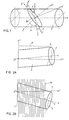
- Figure 1 illustrates in perspective an example of single crystal with its geometric and crystallographic axes and the chosen cutting plane.
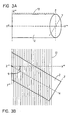
- Figures 2A and 2B illustrate in two views orthogonal the position of the single crystal obtained by a process known and commonly used.
- Figures 3A and 3B show two views orthogonal the position of the single crystal obtained in accordance with the present invention.
- Figure 4 shows a vector diagram of the different repositories used.
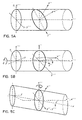
- Figures 5A, 5B, 5C illustrate the occupied positions by the single crystal following the orientation process according to the invention.
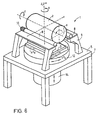
- Figure 6 is a perspective view of a mode of execution of the device for implementing the method.
- the invention gives the possibility to install single crystals on the cutting machine preoriented whose cutting plane is oriented parallel on the cutting plane of the machine and turned according to a perpendicular axis (normal to the cutting plane), so to minimize the cutting length.
- This determination will be done mathematically from the measurements to determine the error of the geometric single crystal with respect to the crystal lattice including the requirements of the subsequent process in relation to the axes crystalline.
- the mounting of the single crystal on its support can then be done using a positioning device which allows the exact measurement of rotation angles of the geometric single crystal, and to mount it as which on a cutting support which is a piece with indexing belonging to the cutting machine.
- the single crystal can be clamped or preferably glued to the support, support which once transferred to the cutting machine will present a perfectly pre-oriented single crystal ready to be sawn without subsequent adjustment.
- the cutting precision will be independent of the machine used or the operator in the case of production chains.
- the positioning device will appear under the shape of a table or frame with a turntable having its vertical axis of rotation z '' 'on which is put the support of the single crystal on which it will be later fixed.
- This support has an indexing system identical to that of the cutting machine.
- the support of the single crystal is an interface piece between the device positioning and cutting machine. He will therefore have the same position on the positioning device and on the cutting machine.
- Above the turntable but fixed relative to the table is a mechanism allowing the single crystal to be held and to rotate it along its horizontal axis x.
- This system is composed in the case of cylindrical single crystals of two cylinders on which rests the single crystal. The single crystal can then rotate along its x axis.
- Plate movement and rotation of the single crystal x allow to position it in any orientation.
- the value of the two angles of rotation will be determined by the requirements of the finished product and calculated mathematically.
- a mechanism brings the support with the single crystal itself while retaining their relative position. This can be done either by elevation of the turntable either by lowering the single crystal. Once brought into contact the single crystal will be clamped or glued in position.
- the single crystal support can then be transferred to the cutting machine.
- the single crystal is then oriented, ready to be cut. Angles of rotation according to x and z '' 'are measured by devices integrated electronics such as encoders or mechanical by verniers for example.
- Figure 1 shows an example of a single crystal to be cut 2 which has a cylindrical geometric shape with geometric axes x, y, z, the x axis being the axis main.
- the axes x ', y', z 'of the crystal lattice of this single crystal are not parallel to the geometric axes.
- the angles a and f between the axes y ', y and z', z are determined by optical or X-ray measurement and define generally the manufacturing error of the single crystal.
- the Figure 1 also shows the cutting plane 16 chosen or imposed single crystal with its inclined y '' and z '' axes angular values p and t with respect to the axes y ', z' of the crystal lattice and the normal x '' to the cutting plane.
- the angular values p and t are generally defined according to the needs of the subsequent use of the cut single crystal. It is understood that these angles p and t could for example be equal to zero in the case where want to get parallel silicon wafers to the plan.
- FIGS. 2A and 2B show in side view and in plan, the position of the single crystal 2 obtained by the process known and commonly used before the present invention by performing an orientation of the single crystal by rotation around the geometric axes y and z.
- the single crystal 2 is then not parallel to the plane of the layer of wires 17 when using a wire saw as cutting means.
- the machine plan x '' ', y' '' of the cutting machine is not parallel to the geometric axis x of the single crystal 1.
- the direction of advancement according to z '' 'of the ply of wires 17 is not perpendicular to the single crystal, which is detrimental to the quality of the cut.
- Figures 3A and 3B illustrate the orientation of the single crystal obtained by the process in accordance with this invention by performing an orientation of the single crystal by rotation around the geometric axes x and z '' '.
- the tablecloth of wire 17 of the saw used as cutting machine lies in the plane x '' 'y' '' and the geometrical axis x of the monocrystal is parallel to this plane x '' ', y' ''.
- the single crystal is therefore in an optimal position with respect to to the cutting means, so as to obtain a cutting very precise.
- the vector diagram of the various reference systems used for positioning is shown in Figure 4 and includes the referential x, y, z linked to the geometric shape of the single crystal, the reference frame x ', y', z 'linked to the network lens of the single crystal, the corresponding reference x '', y '', z '' to the cutting plane of the single crystal and the frame of reference x '' ', y' '', z ''' 'used for the positioning device and the cutting machine.
- the cutting plane corresponds to the plane y '', z '' and its normal corresponds to the direction x ''.
- Misalignment of the geometric shape of the single crystal 2 with the network lens is determined by the angles a and f, corresponding at the angles y'y and z'z.
- the corresponding angles p and t at the angles y''y 'and z''z' determine the orientation cutting plans chosen in relation to the repository of the crystal lattice.
- the normal x '' in the plane of cutting y''z '' defines a vector x '' (x, y, z) which makes a angle g with the geometric axis x and the projection of the vector X '' (x, y, z) on the y plane, z makes an angle d with y.
- the angle d therefore corresponds to the angle of rotation around from the geometric axis x to bring the normal x '' to the plane cutting y '', z '' in a corresponding reference plane on the work plan x '' ', y' '' of the machine.
- the angle g corresponds to the angle of rotation around the vertical axis z '' 'so that the normal x' 'to the plane of cutting is oriented in a reference direction corresponding to the normal x '' 'to the cutting plane y '' 'z' '' of the machine to make the cutting plane coincide desired with the cutting plan of the machine cutting.
- FIGS. 5A, 5B and 5C illustrating three successive positions.
- the single crystal is placed on the positioning device and its geometric axes x, y, z are aligned with the axes x '' ', y' '', z '' 'of the alignment device and the machine cutting.
- the resulting sawing will have well the angles t and p with respect to the crystallographic axes y 'and z'. It is understood that the second rotation can also be done by turning the support cutting an angle -g, the single crystal remaining motionless as is done in the embodiment illustrated in figure 6.
- the latter consists of a positioning device 1 which makes it possible to orient the single crystal 2 outside a cutting machine according to an orientation predetermined with respect to a cutting support is having the form of a support 3 on which the single crystal will be fixed after proper orientation.
- the device positioning 1 includes for this purpose a table or a frame 5 with an upper part 6 and a part lower 7.
- the single crystal 2 is carried by two support cylinders 8 mounted rotating on the upper part 6 with their main axis oriented parallel to the x axis.
- a angular measuring device in the form of an encoder 10 used to measure the angle of rotation d of the single crystal around the x axis.
- a rotary plate 12 is mounted to rotate about the axis z '' 'on the lower part 7 of the chassis.
- a system of angular measurement integrated in the turntable 12 allows measure the angle of rotation g around the z axis' ''.
- the support 3 is maintained in a predetermined orientation precise on the turntable 12.
- the rotary plate 12 is also slidably mounted in the direction z '''on the lower part 7 of the chassis in order to be able to bring the support 3 closer to the single crystal 2 by means of a lifting mechanism 14 to fix the single crystal 2 on the support 3.
- the support 3 and the single crystal 2 can be placed in the cutting machine according to a predetermined geometric position so that the reference plane x ''' s , y''' s of the support 3 corresponds to the plane x ''',y''' of the cutting machine and so that the perpendicular x '''to the cutting plane of the machine is parallel to the reference direction x''' s of the support.
- the process and the device described allow positioning of a single crystal on a support outside the cutting machine in such a way that the single crystal, once mounted with its support on a cutting, or cut with a given orientation of crystalline axes with respect to the saw plane.
- the position of a cylindrical single crystal is such that the generators of it are placed parallel to the ply of wires 17 in the case of a wire saw or parallel to the direction of movement defining the thickness slices if it is a cam cut.
- the orientation of the crystal lattice is measured by relation to the geometric shape of the single crystal optically or by means of X-rays.
- the positioning device or the cutting support can advantageously for this purpose be arranged to be able to be mounted on a generator X-rays so that the positioning of the single crystal can be carried out and checked simultaneously.
- the orientation of the cutting plane y '', z '' relative to the crystal lattice x ', y,' z 'being imposed by the application the values of the two angles of rotation of the single crystal d along the x axis and g along the z axis' '' of the positioning device are determined mathematically. Once the two rotations performed according to the values calculated, the single crystal will be in the position sought for the cutting machine, namely perpendicular to the cutting advance having in addition its cutting plane parallel to that of the machine.
- the positioning device will allow the fixing of the single crystal either by clamping or by gluing on a support pre-indexed in relation to the cutting machine.
- the orientation given by the process minimizes in the case of cylindrical single crystals sawing length.
- the cutting machine therefore requires no device adjustment to ensure cutting according to specifications required after transfer of the single crystal on its cutting support and this one in the cutting machine.
- the wire table of a wire saw remains parallel to the geometric single crystal throughout cutting while ensuring proper orientation of slices thus produced. Likewise, the saw blade of a blade machine remains perpendicular to the single crystal.
- the embodiment described above is in no way limiting and that can receive any desirable modifications inside of the framework as defined by claim 1.
- the two angles of rotation around the x axes and z '' 'could be replaced by angles taken and calculated in relation to other geometric reference systems and crystallographic, but which lead to the same result than normal to the cutting plane of the single crystal is oriented in a corresponding reference direction normal to the cutting plane of the machine and that predetermined geometric axis of the single crystal and the normal on the cutting plane are included in a reference plane corresponding to the work plan of the machine.
- the cutting plane can be determined by others angles that p and t with respect to the crystal lattice and the offset of the crystal lattice from the geometric shape of the single crystal may be indicated by others angles measured as a and f.
- the two support cylinders 8 could be replaced by other means to support the single crystal and to rotate the single crystal such as by example a single support in or on which the single crystal is temporarily fixed and which is rotatably mounted on the table or chassis.
- This rotation support could be arranged at one or two opposite ends of the single crystal.
- the relative rotation between the single crystal and the support cutting around the z axis "'could also be obtained by rotating the single crystal with respect to to the cutting support which would remain stationary on the table or chassis of the positioning device.
- the rotary table would then be replaced by a rotary member according to z "'and carrying the temporary support of the single crystal.
- the angular measurement organs could be electronic, optical or mechanical.
- the approximation or bringing into contact of the single crystal and cutting support could be made by from the bottom or from the top and by moving either the cutting is the single crystal.
- Rotations around the two horizontal and vertical axes x, z "'could be inverted over time by first performing the rotation around the z axis "'and then rotation around the horizontal axis x.
- the method and the device could also be used for the oriented cutting of single crystals any other geometric shape.
Landscapes
- Engineering & Computer Science (AREA)
- Mechanical Engineering (AREA)
- Processing Of Stones Or Stones Resemblance Materials (AREA)
- Crystals, And After-Treatments Of Crystals (AREA)
Claims (7)
- Verfahren für die Ausrichtung eines Einkristalls (2) im Hinblick darauf, ihn in einer Schneidmaschine (17) entlang einer vorbestimmten Schnittebene (y", z") zu schneiden, wonach der Einkristall (2) ausserhalb der Schneidmaschine mittels einer Positioniervorrichtung (1) in einer vorbestimmten Ausrichtung, bezüglich eines Schneidträgers (3) ausgerichtet wird, der Einkristall (2) in Übereinstimmung mit der benannten, vorbestimmten Ausrichtung auf dem Schneidträger (3) befestigt wird, dessen räumliche Anordnung in der Schneidmaschine (17) bezüglich einer zu einer Arbeitsebene (x"', y"') der Schneidmaschine (17) rechtwinkligen Schneidebene (y"', z"') geometrisch definiert ist, und der Schneidträger (3) nach Befestigung des Einkristalls gemäss der benannten, geometrisch definierten räumlichen Anordnung in der Schneidmaschine (17) angebracht wird, dadurch gekennzeichnet, dass die benannte, vorbestimmte Ausrichtung erhalten wird, indem , der Einkristall (2) so auf der Positioniervorrichtung (1) angebracht wird, dass eine seiner geometrischen Achsen (x) aus der geometrischen Gestalt (x, y, z) des Einkristalls in einer Bezugsebene enthalten ist, die der Arbeitsebene (x"', y"') der Schneidmaschine (17) entspricht, indem eine Drehung des Einkristalls um einen ersten vorbestimmten Winkel (d) um die benannte geometrische Achse (x) ausgeführt wird, um die Normale (x") zur Schnittebene (y", z") des Einkristalls in die benannte Bezugsebene zu bringen, und indem eine relative Drehung zwischen dem Schneidträger (3) und dem Einkristall um einen zweiten vorbestimmten Winkel (g) um eine zu der benannten Bezugsebene senkrechten Achse (z"') ausgeführt wird, damit die Normale (x") zur Schnittebene (y", z") einer Bezugsrichtung folgend ausgerichtet wird, die der Normalen zur Schneidebene (y"', z"') der Maschine entspricht, wobei die benannte geometrische Achse (x) und die Normale (x") zur Schnittebene des Einkristalls (2) in der benannten Bezugsebene enthalten sind.
- Verfahren gemäss Anspruch 1, dadurch gekennzeichnet, dass der erste und zweite Drehwinkel (d, g) mathematisch bestimmt werden.
- Verfahren gemäss Anspruch 2, dadurch gekennzeichnet, dass die Ausrichtung der Schnittebene (y", z") des Einkristalls bezüglich des Kristallgitters (x', y', z') definiert wird, dass die Ausrichtung des Kristallgitters (x', y', z') bezüglich der geometrischen Gestalt (x, y, z) des Einkristalls gemessen wird, und dass der erste und zweite Drehwinkel (d, g) berechnet wird, wobei die Ausrichtung der Schnittebene (y", z") bezüglich des Kristallgitters (x', y', z') und bezüglich der geometrischen Gestalt (x, y, z) des Einkristalls berücksichtigt wird.
- Verfahren gemäss Anspruch 3, dadurch gekennzeichnet, dass die Ausrichtung des Kristallgitters (x', y', z') bezüglich der geometrischen Gestalt (x, y, z) optisch oder mittels Röntgenstrahlen bestimmt wird.
- Verfahren gemäss einem der Ansprüche 1 bis 4, dadurch gekennzeichnet, dass ein Einkristall (2) verwendet wird, dessen geometrische Gestalt im Wesentlichen kreiszylindrisch ist, wobei die benannte geometrische Achse (x) der Hauptachse des Einkristalls entspricht, und dass der Einkristall auf zwei sich drehenden, parallelen Zylindern (8) der Positioniervorrichtung (1) angebracht wird, wobei die Achsen der zwei Zylinder (8) zu der benannten Bezugsebene parallel sind.
- Vorrichtung zur Realisierung des Verfahrens gemäss einem der vorangehenden Ansprüche, dadurch gekennzeichnet, dass sieeine Gesamtheit zur Positionierung mit einem Schneidträger (3) und eine Positioniervorrichtung (1) aufweist, die dafür bestimmt ist, den Einkristall (2) ausserhalb der Schneidmaschine in Übereinstimmung mit einer vorbestimmten Ausrichtung bezüglich des besagten Schneidträgers (3) auszurichten, auf dem der Einkristall (2) befestigt werden soll und dessen räumliche Anordnung in der Schneidmaschine geometrisch definiert ist, und dessen Hauptachsen (x"'s, y"'s) zu den Achsen (x"', y"') der Schneidmaschine parallel sind,erste Mittel (8), um den Einkristall zu halten, und um eine Drehung des Einkristalls zu bewirken,zweite Mittel (12), um eine relative Drehung zwischen dem Schneidträger (3) und dem Einkristall (2) zu bewirken,dritte Mittel (14), um eine relative Translationsbewegung zwischen dem Einkristall (2) und dem Schneidträger (3) zu bewirken, die dazu bestimmt sind, den Schneidträger (3) und den Einkristall (2) im Hinblick darauf einander zu nähern, dass letzterer in der benannten vorbestimmten Ausrichtung auf dem Schneidträger befestigt wird,wobei die besagten ersten Mittel zwei parallele, zylindrische Träger, die drehbar an einem Gestell (5) der Positioniervorrichtung (1) angebracht und so ausgelegt sind, den Einkristall (2) zu halten, sowie ein erstes Winkelmessorgan (10), mit dem ein erster vorbestimmter Drehwinkel (d) bestimmt werden kann, umfassen,wobei die besagten zweiten Mittel eine bezüglich des benannten Gestells (5) drehbar angebrachte Drehscheibe (12) umfassen, deren Hauptebene parallel zu den Achsen der benannten zylindrischen Träger (8) ist, wobei diese Drehscheibe (12) so ausgelegt ist, dass sie den Schneidträger (3) in einer geometrisch definierten Lage hält, und ein zweites Winkelmessorgan vorgesehen ist, um einen zweiten, vorbestimmten Drehwinkel (g) zu messen,wobei die besagten dritten Mittel einen verschieburgsmechanismus (14) aufweisen, der die Annäberung des Schneidträgers (3) und des Einkristalls (2) gestattet,wobei die besagten ersten Mittel es erlauben den Einkristall in einer solchen Ausrichtung zu halten, dass eine der geometrischen Achsen (x) der geometrischen Gestalt (x, y, z) des Einkristalls in einer der Arbeitsebene (x"', y"') der Schneidmaschine entsprechenden Bezugsebene enthalten ist,wobei die besagten ersten Mittel es erlauben, eine Drehung des Einkristalls um einen ersten vorbestimmten Winkel (d) um die benannte geometrische Achse (x) zu bewirken, damit die Normale (x") zur Schnittebene (x", z") des Einkristalls in die benannte Bezugsebene gebracht wird,wobei die besagten zweiten Mittel es erlauben, eine relative Drehung zwischen dem Schneidträger und dem Einkristall um einen zweiter vorbestimmten Winkel (g) um eine zu der benannten Bezugsebene senkrechten Achse (z"') zu bewirken, damit die Normale (x") zur Schnittebene (y", z") in einer Bezugsrichtung ausgerichtet wird, die der Normalen zur Schneidebene (y"', z"') der Maschine entspricht,wobei besagtes erstes Winkelmessorgan (10) dazu bestimmt ist, den ersten vorbestimmten Drehwinkel (d) zu bestimmen,wobei besagtes zweites Winkelmessorgan vorgesehen ist, um den besagten zweiten vorbestimmten Drehwinkel (g) zu bestimmen,wobei der besagte Schneidträger (3) so gestaltet ist, dass seine Positionierung in der Schneidmaschine gemäss einer geometrischen Lage erfolgt, die der auf der benannten Drehscheibe definierten geometrischen Lage entspricht, so dass die Bezugsebene und die Bezugsrichtung der Arbeitsebene (x"', y"') und der Normalen (x"') zur Schneidebene der Maschine entsprechen.
- Vorrichtung gemäss Anspruch 6, dadurch gekennzeichnet, dass der Schneidtrager (3) oder die Positioniervorrichtung (1) so ausgelegt sind, dass sie auf einen Röntgenstrahlengenerator angebracht werden können.
Applications Claiming Priority (6)
| Application Number | Priority Date | Filing Date | Title |
|---|---|---|---|
| CH113695 | 1995-04-22 | ||
| CH1136/95 | 1995-04-22 | ||
| CH113595A CH690422A5 (fr) | 1995-04-22 | 1995-04-22 | Dispositif pour l'orientation de monocristaux en vue d'une découpe dans un plan prédéterminé et selon une direction qui minimise la longueur de coupe. |
| CH113695A CH690423A5 (fr) | 1995-04-22 | 1995-04-22 | Procédé pour l'orientation de monocristaux en vue d'une découpe en tranches dans une direction prédéterminée. |
| CH1135/95 | 1995-04-22 | ||
| CH113595 | 1995-04-22 |
Publications (2)
| Publication Number | Publication Date |
|---|---|
| EP0738572A1 EP0738572A1 (de) | 1996-10-23 |
| EP0738572B1 true EP0738572B1 (de) | 2004-01-21 |
Family
ID=25686755
Family Applications (1)
| Application Number | Title | Priority Date | Filing Date |
|---|---|---|---|
| EP96105699A Expired - Lifetime EP0738572B1 (de) | 1995-04-22 | 1996-04-11 | Verfahren zur Orientierung von Einkristallen zum Schneiden in eine Schneidemaschine und Einrichtung zur Durchführung des Verfahrens |
Country Status (4)
| Country | Link |
|---|---|
| US (1) | US5720271A (de) |
| EP (1) | EP0738572B1 (de) |
| JP (1) | JPH08294914A (de) |
| DE (1) | DE69631353T2 (de) |
Families Citing this family (32)
| Publication number | Priority date | Publication date | Assignee | Title |
|---|---|---|---|---|
| TW355151B (en) * | 1995-07-07 | 1999-04-01 | Tokyo Seimitsu Co Ltd | A method for cutting single chip material by the steel saw |
| US6024814A (en) * | 1995-11-30 | 2000-02-15 | Nippei Toyama Corporation | Method for processing ingots |
| JP3397968B2 (ja) * | 1996-03-29 | 2003-04-21 | 信越半導体株式会社 | 半導体単結晶インゴットのスライス方法 |
| CH691045A5 (fr) * | 1996-04-16 | 2001-04-12 | Hct Shaping Systems Sa | Procédé pour l'orientation de plusieurs pièces cristallines posées côte à côte sur un support de découpage en vue d'une découpe simultanée dans une machine de découpage et dispositif pour la |
| CH692331A5 (de) * | 1996-06-04 | 2002-05-15 | Tokyo Seimitsu Co Ltd | Drahtsäge und Schneidverfahren unter Einsatz derselben. |
| CA2220776A1 (en) * | 1996-11-13 | 1998-05-13 | Allen Sommers | Eccentric grinder loading system |
| JPH10160688A (ja) * | 1996-12-04 | 1998-06-19 | Rigaku Corp | 単結晶インゴットのx線トポグラフィー方法および装置 |
| JP3137600B2 (ja) * | 1997-09-12 | 2001-02-26 | 株式会社日平トヤマ | ワークの結晶方位調整方法 |
| DE19825050C2 (de) * | 1998-06-04 | 2002-06-13 | Wacker Siltronic Halbleitermat | Verfahren zum Anordnen und Orientieren von Einkristallen zum Abtrennen von Scheiben auf einer ein Drahtgatter aufweisenden Drahtsäge |
| DE19825051A1 (de) * | 1998-06-04 | 1999-12-09 | Wacker Siltronic Halbleitermat | Verfahren und Vorrichtung zur Herstellung eines zylinderförmigen Einkristalls und Verfahren zum Abtrennen von Halbleiterscheiben |
| US6055293A (en) * | 1998-06-30 | 2000-04-25 | Seh America, Inc. | Method for identifying desired features in a crystal |
| US6106365A (en) * | 1998-11-06 | 2000-08-22 | Seh America, Inc. | Method and apparatus to control mounting pressure of semiconductor crystals |
| DE60033574T2 (de) | 2000-05-31 | 2007-11-15 | Memc Electronic Materials S.P.A. | Drahtsäge und verfahren zum gleichzeitigen schneiden von halbleiterbarren |
| DE10052154A1 (de) * | 2000-10-20 | 2002-05-08 | Freiberger Compound Mat Gmbh | Verfahren und Vorrichtung zum Trennen von Einkristallen, Justiervorrichtung und Testverfahren zum Ermitteln einer Orientierung eines Einkristalls für ein derartiges Verfahren |
| US6659976B2 (en) * | 2001-04-16 | 2003-12-09 | Zevek, Inc. | Feeding set adaptor |
| US6760403B2 (en) | 2001-10-25 | 2004-07-06 | Seh America, Inc. | Method and apparatus for orienting a crystalline body during radiation diffractometry |
| US7027557B2 (en) * | 2004-05-13 | 2006-04-11 | Jorge Llacer | Method for assisted beam selection in radiation therapy planning |
| EP1819473A1 (de) * | 2004-12-10 | 2007-08-22 | Freiberger Compound Materials GmbH | Werkst]ckhalterung und verfahren zum drahts[gen |
| KR20100094484A (ko) * | 2007-12-19 | 2010-08-26 | 아사히 가라스 가부시키가이샤 | 에테르 조성물 |
| DE102010010886A1 (de) * | 2010-03-10 | 2011-09-15 | Siltronic Ag | Verfahren zur Bearbeitung einer Halbleiterscheibe |
| US8259901B1 (en) | 2010-05-25 | 2012-09-04 | Rubicon Technology, Inc. | Intelligent machines and process for production of monocrystalline products with goniometer continual feedback |
| EP2520401A1 (de) * | 2011-05-05 | 2012-11-07 | Meyer Burger AG | Verfahren zur Befestigung eines auf einer Verarbeitungsvorrichtung zu behandelnden Einkristallwerkstücks |
| CN102581976B (zh) * | 2012-03-14 | 2015-04-29 | 浙江昀丰新能源科技有限公司 | 一种晶体加工用定向装置 |
| DE102012210047A1 (de) * | 2012-06-14 | 2013-12-19 | Crystal-N Gmbh | Verfahren zum Schneiden eines Einkristalls |
| CN103171059B (zh) * | 2013-03-07 | 2015-02-25 | 贵阳嘉瑜光电科技咨询中心 | 一种用于蓝宝石加工晶向实时测量的夹具及其测量方法 |
| US9682495B2 (en) * | 2013-09-30 | 2017-06-20 | Gtat Corporation | Method and apparatus for processing sapphire |
| CN104493982A (zh) * | 2014-12-30 | 2015-04-08 | 南京铭品机械制造有限公司 | 一种数控丝锯加工机 |
| CN107020706B (zh) * | 2017-04-27 | 2018-08-07 | 桂林电子科技大学 | 一种小尺寸单晶定向夹具 |
| DE102018221922A1 (de) | 2018-12-17 | 2020-06-18 | Siltronic Ag | Verfahren zur Herstellung von Halbleiterscheiben mittels einer Drahtsäge, Drahtsäge und Halbleiterscheibe aus einkristallinem Silizium |
| CN110216801A (zh) * | 2019-07-09 | 2019-09-10 | 南通友拓新能源科技有限公司 | 一种尺寸可调的硅片切割方法 |
| DE102020209092A1 (de) * | 2020-07-21 | 2022-01-27 | Sicrystal Gmbh | Kristallstrukturorientierung in Halbleiter-Halbzeugen und Halbleitersubstraten zum Verringern von Sprüngen und Verfahren zum Einstellen von dieser |
| CN112760617B (zh) * | 2020-12-30 | 2023-04-07 | 上海埃延半导体有限公司 | 化学气相沉积用的非金属反应腔及其使用方法 |
Family Cites Families (11)
| Publication number | Priority date | Publication date | Assignee | Title |
|---|---|---|---|---|
| NL105904C (de) * | 1955-12-30 | |||
| DE2752925A1 (de) * | 1977-11-26 | 1979-05-31 | Philips Patentverwaltung | Vorrichtung zum ausrichten und festlegen eines einkristalles |
| GB8325544D0 (en) * | 1983-09-23 | 1983-10-26 | Howe S H | Orienting crystals |
| JP2673544B2 (ja) * | 1988-06-14 | 1997-11-05 | 株式会社日平トヤマ | 脆性材料の切断方法 |
| WO1990005053A1 (fr) * | 1988-11-03 | 1990-05-17 | Photec Industrie S.A. | Unite de clivage par abrasion |
| JP2883667B2 (ja) * | 1990-03-07 | 1999-04-19 | 理学電機株式会社 | 単結晶インゴットの結晶方位測定装置 |
| JPH0820384B2 (ja) * | 1991-02-19 | 1996-03-04 | 信越半導体株式会社 | 単結晶のof方位検出方法及び装置 |
| JP2516717B2 (ja) * | 1991-11-29 | 1996-07-24 | 信越半導体株式会社 | ワイヤソ―及びその切断方法 |
| JP3205402B2 (ja) * | 1992-09-09 | 2001-09-04 | 東芝アイティー・コントロールシステム株式会社 | 結晶方位決定方法及び装置 |
| JPH06229953A (ja) * | 1993-02-04 | 1994-08-19 | Rigaku Corp | 単結晶材料の結晶格子面測定装置 |
| JP2755907B2 (ja) * | 1994-06-28 | 1998-05-25 | 信越半導体株式会社 | ワイヤソー用溝ローラ |
-
1996
- 1996-04-11 EP EP96105699A patent/EP0738572B1/de not_active Expired - Lifetime
- 1996-04-11 DE DE69631353T patent/DE69631353T2/de not_active Expired - Lifetime
- 1996-04-19 US US08/634,801 patent/US5720271A/en not_active Expired - Lifetime
- 1996-04-22 JP JP8122830A patent/JPH08294914A/ja active Pending
Also Published As
| Publication number | Publication date |
|---|---|
| US5720271A (en) | 1998-02-24 |
| JPH08294914A (ja) | 1996-11-12 |
| DE69631353T2 (de) | 2004-12-09 |
| DE69631353D1 (de) | 2004-02-26 |
| EP0738572A1 (de) | 1996-10-23 |
Similar Documents
| Publication | Publication Date | Title |
|---|---|---|
| EP0738572B1 (de) | Verfahren zur Orientierung von Einkristallen zum Schneiden in eine Schneidemaschine und Einrichtung zur Durchführung des Verfahrens | |
| EP0802029B1 (de) | Verfahren zum Orientieren von mehreren Einkristallbarren auf einem Träger für das gleichzeitige Aufschneiden der Barren in einer Schneidmaschine | |
| FR2874263A1 (fr) | Procede et dispositif pour la mesure, l'orientation et la fixation d'au moins un monocristal | |
| EP1095744A1 (de) | Maschine zum Lochen von Platten | |
| JP6430329B2 (ja) | 切断装置及び切断方法 | |
| EP0581671A1 (de) | Verfahren zur Ankopplung einer Glasfaser an einen optischen Baustein auf einem gemeinsamen Substrat | |
| TWM549782U (zh) | 晶棒切片設備及其調整裝置 | |
| FR2687804A1 (fr) | Tambour pour phototraceur et procedes pour sa fabrication et son alignement. | |
| CA2655636A1 (fr) | Procede et machine d'usinage pour objet optique | |
| CH690422A5 (fr) | Dispositif pour l'orientation de monocristaux en vue d'une découpe dans un plan prédéterminé et selon une direction qui minimise la longueur de coupe. | |
| FR2685239A1 (fr) | Machine pour l'usinage de pieces a partir de profiles de grande longueur. | |
| EP0241061A2 (de) | Vorrichtung zu Messung der Orientierung massiver Einkristallmaterialien mit Verwendung des Laue-Verfahrens | |
| CH690423A5 (fr) | Procédé pour l'orientation de monocristaux en vue d'une découpe en tranches dans une direction prédéterminée. | |
| FR2629008A1 (fr) | Procede et dispositif de clivage d'une plaquette de silicium | |
| FR2711331A1 (fr) | Machine à déborder pour verre de lunettes. | |
| EP1062670B1 (de) | Verfahren zum zusammenstellen einer optischen einheit mit koaxialen schalen, insbesondere für ein röntgenteleskop | |
| FR2481980A1 (fr) | Machine de rectification de materiaux durs et notamment de quartz | |
| WO2007054509A1 (fr) | Systeme de positionnement d'un composant, outillage de reglage et procede de reglage | |
| FR2755298A1 (fr) | Procede et dispositif pour le positionnement precis d'objets monocristallins les uns par rapports aux autres en fonction de leurs plans cristallographiques | |
| EP0478439A1 (de) | Maschine zur Herstellung von geschliffenen Schrauben ausgehend von Stäben | |
| JPH01180507A (ja) | 光軸調整方法 | |
| FR2910832A1 (fr) | Dispositif porte-pieces orientale | |
| EP1801627A2 (de) | Aufbau mit einer Kontaklinsenaufnahme und Methode zum Verwendung derselben | |
| FR2794284A1 (fr) | Procede et outillage de coupe de produits semiconducteurs | |
| FR3071327B1 (fr) | Procede et systeme d'alignement de l'axe optique d'un cable optique avec un composant optoelectronique |
Legal Events
| Date | Code | Title | Description |
|---|---|---|---|
| PUAI | Public reference made under article 153(3) epc to a published international application that has entered the european phase |
Free format text: ORIGINAL CODE: 0009012 |
|
| AK | Designated contracting states |
Kind code of ref document: A1 Designated state(s): DE FR GB IT |
|
| 17P | Request for examination filed |
Effective date: 19970121 |
|
| RAP1 | Party data changed (applicant data changed or rights of an application transferred) |
Owner name: HCT SHAPING SYSTEMS SA |
|
| RIN1 | Information on inventor provided before grant (corrected) |
Inventor name: HAUSER, CHARLES |
|
| 17Q | First examination report despatched |
Effective date: 20010430 |
|
| GRAP | Despatch of communication of intention to grant a patent |
Free format text: ORIGINAL CODE: EPIDOSNIGR1 |
|
| GRAS | Grant fee paid |
Free format text: ORIGINAL CODE: EPIDOSNIGR3 |
|
| GRAA | (expected) grant |
Free format text: ORIGINAL CODE: 0009210 |
|
| AK | Designated contracting states |
Kind code of ref document: B1 Designated state(s): DE FR GB IT |
|
| REG | Reference to a national code |
Ref country code: GB Ref legal event code: FG4D Free format text: NOT ENGLISH |
|
| REF | Corresponds to: |
Ref document number: 69631353 Country of ref document: DE Date of ref document: 20040226 Kind code of ref document: P |
|
| GBT | Gb: translation of ep patent filed (gb section 77(6)(a)/1977) |
Effective date: 20040316 |
|
| PLBE | No opposition filed within time limit |
Free format text: ORIGINAL CODE: 0009261 |
|
| STAA | Information on the status of an ep patent application or granted ep patent |
Free format text: STATUS: NO OPPOSITION FILED WITHIN TIME LIMIT |
|
| 26N | No opposition filed |
Effective date: 20041022 |
|
| REG | Reference to a national code |
Ref country code: FR Ref legal event code: CD |
|
| PGFP | Annual fee paid to national office [announced via postgrant information from national office to epo] |
Ref country code: DE Payment date: 20110421 Year of fee payment: 16 Ref country code: FR Payment date: 20110510 Year of fee payment: 16 |
|
| PGFP | Annual fee paid to national office [announced via postgrant information from national office to epo] |
Ref country code: GB Payment date: 20110421 Year of fee payment: 16 |
|
| PGFP | Annual fee paid to national office [announced via postgrant information from national office to epo] |
Ref country code: IT Payment date: 20110422 Year of fee payment: 16 |
|
| GBPC | Gb: european patent ceased through non-payment of renewal fee |
Effective date: 20120411 |
|
| REG | Reference to a national code |
Ref country code: FR Ref legal event code: ST Effective date: 20121228 |
|
| PG25 | Lapsed in a contracting state [announced via postgrant information from national office to epo] |
Ref country code: GB Free format text: LAPSE BECAUSE OF NON-PAYMENT OF DUE FEES Effective date: 20120411 |
|
| REG | Reference to a national code |
Ref country code: DE Ref legal event code: R119 Ref document number: 69631353 Country of ref document: DE Effective date: 20121101 |
|
| PG25 | Lapsed in a contracting state [announced via postgrant information from national office to epo] |
Ref country code: FR Free format text: LAPSE BECAUSE OF NON-PAYMENT OF DUE FEES Effective date: 20120430 Ref country code: IT Free format text: LAPSE BECAUSE OF NON-PAYMENT OF DUE FEES Effective date: 20120411 |
|
| PG25 | Lapsed in a contracting state [announced via postgrant information from national office to epo] |
Ref country code: DE Free format text: LAPSE BECAUSE OF NON-PAYMENT OF DUE FEES Effective date: 20121101 |