EP0738598B1 - Antriebsvorrichtung zur Erzeugung eines Strahles von Tintentröpfchen - Google Patents
Antriebsvorrichtung zur Erzeugung eines Strahles von Tintentröpfchen Download PDFInfo
- Publication number
- EP0738598B1 EP0738598B1 EP96106138A EP96106138A EP0738598B1 EP 0738598 B1 EP0738598 B1 EP 0738598B1 EP 96106138 A EP96106138 A EP 96106138A EP 96106138 A EP96106138 A EP 96106138A EP 0738598 B1 EP0738598 B1 EP 0738598B1
- Authority
- EP
- European Patent Office
- Prior art keywords
- voltage waveform
- ink
- drive
- drive signal
- voltage
- Prior art date
- Legal status (The legal status is an assumption and is not a legal conclusion. Google has not performed a legal analysis and makes no representation as to the accuracy of the status listed.)
- Expired - Lifetime
Links
Images


Classifications
-
- B—PERFORMING OPERATIONS; TRANSPORTING
- B41—PRINTING; LINING MACHINES; TYPEWRITERS; STAMPS
- B41J—TYPEWRITERS; SELECTIVE PRINTING MECHANISMS, i.e. MECHANISMS PRINTING OTHERWISE THAN FROM A FORME; CORRECTION OF TYPOGRAPHICAL ERRORS
- B41J2/00—Typewriters or selective printing mechanisms characterised by the printing or marking process for which they are designed
- B41J2/005—Typewriters or selective printing mechanisms characterised by the printing or marking process for which they are designed characterised by bringing liquid or particles selectively into contact with a printing material
- B41J2/01—Ink jet
- B41J2/015—Ink jet characterised by the jet generation process
- B41J2/04—Ink jet characterised by the jet generation process generating single droplets or particles on demand
- B41J2/045—Ink jet characterised by the jet generation process generating single droplets or particles on demand by pressure, e.g. electromechanical transducers
- B41J2/04501—Control methods or devices therefor, e.g. driver circuits, control circuits
- B41J2/04541—Specific driving circuit
-
- B—PERFORMING OPERATIONS; TRANSPORTING
- B41—PRINTING; LINING MACHINES; TYPEWRITERS; STAMPS
- B41J—TYPEWRITERS; SELECTIVE PRINTING MECHANISMS, i.e. MECHANISMS PRINTING OTHERWISE THAN FROM A FORME; CORRECTION OF TYPOGRAPHICAL ERRORS
- B41J2/00—Typewriters or selective printing mechanisms characterised by the printing or marking process for which they are designed
- B41J2/005—Typewriters or selective printing mechanisms characterised by the printing or marking process for which they are designed characterised by bringing liquid or particles selectively into contact with a printing material
- B41J2/01—Ink jet
- B41J2/015—Ink jet characterised by the jet generation process
- B41J2/04—Ink jet characterised by the jet generation process generating single droplets or particles on demand
- B41J2/045—Ink jet characterised by the jet generation process generating single droplets or particles on demand by pressure, e.g. electromechanical transducers
- B41J2/04501—Control methods or devices therefor, e.g. driver circuits, control circuits
- B41J2/04581—Control methods or devices therefor, e.g. driver circuits, control circuits controlling heads based on piezoelectric elements
-
- B—PERFORMING OPERATIONS; TRANSPORTING
- B41—PRINTING; LINING MACHINES; TYPEWRITERS; STAMPS
- B41J—TYPEWRITERS; SELECTIVE PRINTING MECHANISMS, i.e. MECHANISMS PRINTING OTHERWISE THAN FROM A FORME; CORRECTION OF TYPOGRAPHICAL ERRORS
- B41J2/00—Typewriters or selective printing mechanisms characterised by the printing or marking process for which they are designed
- B41J2/005—Typewriters or selective printing mechanisms characterised by the printing or marking process for which they are designed characterised by bringing liquid or particles selectively into contact with a printing material
- B41J2/01—Ink jet
- B41J2/015—Ink jet characterised by the jet generation process
- B41J2/04—Ink jet characterised by the jet generation process generating single droplets or particles on demand
- B41J2/045—Ink jet characterised by the jet generation process generating single droplets or particles on demand by pressure, e.g. electromechanical transducers
- B41J2/04501—Control methods or devices therefor, e.g. driver circuits, control circuits
- B41J2/04588—Control methods or devices therefor, e.g. driver circuits, control circuits using a specific waveform
-
- B—PERFORMING OPERATIONS; TRANSPORTING
- B41—PRINTING; LINING MACHINES; TYPEWRITERS; STAMPS
- B41J—TYPEWRITERS; SELECTIVE PRINTING MECHANISMS, i.e. MECHANISMS PRINTING OTHERWISE THAN FROM A FORME; CORRECTION OF TYPOGRAPHICAL ERRORS
- B41J2/00—Typewriters or selective printing mechanisms characterised by the printing or marking process for which they are designed
- B41J2/005—Typewriters or selective printing mechanisms characterised by the printing or marking process for which they are designed characterised by bringing liquid or particles selectively into contact with a printing material
- B41J2/01—Ink jet
- B41J2/015—Ink jet characterised by the jet generation process
- B41J2/04—Ink jet characterised by the jet generation process generating single droplets or particles on demand
- B41J2/045—Ink jet characterised by the jet generation process generating single droplets or particles on demand by pressure, e.g. electromechanical transducers
- B41J2/04501—Control methods or devices therefor, e.g. driver circuits, control circuits
- B41J2/04593—Dot-size modulation by changing the size of the drop
-
- B—PERFORMING OPERATIONS; TRANSPORTING
- B41—PRINTING; LINING MACHINES; TYPEWRITERS; STAMPS
- B41J—TYPEWRITERS; SELECTIVE PRINTING MECHANISMS, i.e. MECHANISMS PRINTING OTHERWISE THAN FROM A FORME; CORRECTION OF TYPOGRAPHICAL ERRORS
- B41J2/00—Typewriters or selective printing mechanisms characterised by the printing or marking process for which they are designed
- B41J2/005—Typewriters or selective printing mechanisms characterised by the printing or marking process for which they are designed characterised by bringing liquid or particles selectively into contact with a printing material
- B41J2/01—Ink jet
- B41J2/21—Ink jet for multi-colour printing
- B41J2/2121—Ink jet for multi-colour printing characterised by dot size, e.g. combinations of printed dots of different diameter
- B41J2/2128—Ink jet for multi-colour printing characterised by dot size, e.g. combinations of printed dots of different diameter by means of energy modulation
Definitions
- This invention relates to a printing head drive device of an ink jet printer.
- An ink jet printer is one type of dot matrix printer.
- ink droplets are jetted onto the recording sheet according to binary-coded image signals, so that a character or image is formed with recording dots having the same size.
- it is essential to reduce the weight of each ink droplet, and therefore the size of the resultant recording dot. If the size of the resultant recording dot is not reduced, the low density region of the printed image will have significant granularity.
- a method of decreasing the weight of ink droplets has been disclosed in Japanese Patent Application (OPI) No. 17589/1980.
- the volume of the pressure chamber is changed, i.e., the chamber is expanded and contracted.
- the weight of the ink droplets is reduced by decreasing the force of expanding and contracting the pressure chamber.
- the high density region of the formed image must be filled completely with ink dots with no spaces between the ink dots. Hence, if the size of each recording dot is decreased, then the printing speed is decreased as much (when compared with the case where the recording dots are large).
- print resolving powers are 360 dpi and 720 dpi.
- the recording dots in order to completely fill the recording sheets with the recording dots, i.e., to form solid prints, the recording dots must be at least 100 ⁇ m and 50 ⁇ m, respectively.
- the print resolving power is 720 dpi
- the printing speed is decreased to about a quarter (1/4) of that in the case where the print resolving power is 360 dpi.
- to do so is rather difficult.
- document JP-A-63 182 153 discloses an ink jet recorder capable of performing multi-gradational recording by using large and small diameter ink droplets.
- a sine wave supplied from a high frequency power source used to generate ink droplets through excitation of a nozzle is controlled in voltage by two volume controls.
- a relay selects one of the two voltages. If the relay selects the first exciting voltage sent from the first volume control, large diameter droplets are generated, while small diameter droplets are generated if the second exciting voltage sent from the second volume control is selected. Because the switching time of a relay is slow compared to the period of the high-frequency voltage, in this technique many ink droplets of one size are generated before the operation is switched to the generation of droplets of the other size.
- the present invention intends to overcome the above problems.
- the object is solved by the ink jet type printing head drive device according to independent claim 1.
- the present invention generally relates to a drive device for a printing head of an ink jet printer in which different size ink droplets are jetted from the same nozzle onto a recording medium such as a recording sheet.
- a drive device for an ink jet type printing head which is able to jet ink droplets having different diameters from the same nozzle without changing the printing speed.
- a drive device for an ink jet type printing head in which a pressure generating chamber is expanded and contracted with a piezo-electric element which is confronted with the pressure generating chamber to cause a nozzle opening to jet ink droplets, wherein
- an ink jet type printing head drive device in which a piezo-electric element confronts a pressure generating chamber and the chamber is expanded and contracted by the piezo-electric element to jet ink droplets from a nozzle opening, the drive device comprising:
- the drive device for an ink jet type printing head makes it possible to jet ink droplets having different sizes from the same nozzle, whereby the resultant image is high in picture quality and in gradation, and the printing operation is achieved at high speed.
- the drive device includes a drive signal generating circuit which outputs within one printing period a first drive signal which is used to jet a relatively large ink droplet from the nozzle opening, and a second drive signal in succession to the first drive signal which is used to jet a relatively small ink droplet from the same nozzle opening.
- a printing signal one of the first and second drive signals is selected and applied to the piezo-electric elements of the printing head.
- ink droplets having different sizes are jetted from the same ink nozzle.
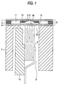
- FIG. 1 shows an example of an ink jet type printing head to which the technical concept of the invention is applied.
- reference numeral 1 designates a nozzle plate having a nozzle opening 2; and 3, a flow-path forming board.
- the board 3 has a through-hole defining a pressure generating chamber 9, through-holes or grooves defining ink supplying holes 10, and a through-hole defining a common ink chamber 11.
- reference numeral 4 designates a vibrating board which elastically deforms itself and is in abutment with the end of a piezo-electric element 6.
- the nozzle plate 1 and the vibrating board 4 are set on both sides of the flow-path forming board 3, thus forming a base board unit 5.
- reference numeral 7 designates a base stand including a chamber 8 in which the piezo-electric element 6 is vibratingly accommodated.
- the piezo-electric element 6 is fixed through a fixing board 13 so that the island portion 4a of the vibrating board 4 is in abutment with the end of the piezo-electric element 6.
- FIG. 2 is a block diagram showing an example of a drive circuit for driving the above-described printing head.
- reference numeral 22 designates a memory for temporarily storing printing data; 23, a drive signal generating circuit for generating drive signals to vibrate (expand and contract) the piezo-electric element 6 of the aforementioned printing head; 27, a shift register for storing printing data which are transferred, in a serial mode, from the memory 22; and 26, a latch circuit for latching all the printing data at the same time which have been stored in the shift register 27.
- the output of the latch circuit 26 is applied to the control terminals of selecting circuits, namely, transistors "S", to control the conduction of those transistors "S".
- the aforementioned memory 22, drive signal generating circuit 23, latch circuit 26, and shift register 27 are controlled by a control circuit 21.
- a diode "D" is connected between the collector and the emitter as shown in FIG. 2.
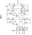
- FIG. 3 is a circuit diagram showing an example of the drive signal generating circuit 23.
- reference characters IN1 and IN3 denote input terminals to which a charge signal is applied for contracting the piezo-electric element 6; and IN2 and IN4, input terminals to which a discharge signal is applied for expanding the piezo-electric element 6.
- the control circuit 21 applies pulse signals (which, as shown in FIG. 4, have pulse widths T1, T2, T3 and T4, respectively,) to the input terminals IN1, IN2, IN3, and IN4, respectively.
- pulse signals which, as shown in FIG. 4, have pulse widths T1, T2, T3 and T4, respectively,
- the pulse signal (T1) applied to the input terminal IN1 is applied through a level shifting transistor Q1 to a first constant current charge circuit 30, which comprises transistors Q2 and Q3 and a resistor R1, to operate the circuit 30.
- a capacitor C is charged with a constant current value.
- the terminal voltage of the capacitor C is raised to a predetermined voltage in a period of time ⁇ 1.
- a voltage which is substantially equal to the terminal voltage is applied through a current amplifier circuit 34 to an output terminal OUT.
- a voltage waveform formed by this pulse signal (T1) will be referred to as "a first voltage waveform".
- the pulse signal (T3) applied to the input terminal IN3 is applied through a level shifting transistor Q4 to a second constant current charge circuit 31, which comprises transistors Q5 and Q6 and a resistor R2, to operate the circuit 31.
- the capacitor C is charged with a constant current value.
- the terminal voltage of the capacitor C is raised to a predetermined voltage in a period of time ⁇ 4.
- a voltage which is substantially equal to the terminal voltage of the capacitor is applied through the current amplifier circuit 34 to an output terminal OUT.
- a voltage waveform formed by this pulse signal (T3) will be referred to as "a fourth voltage waveform".
- a voltage which is substantially equal to the terminal voltage of the capacitor C is applied through the current amplifier circuit 34 to the output terminal OUT.
- a voltage waveform formed by this pulse signal (T2) will be referred to as "a third voltage waveform”.
- the terminal voltage of the capacitor C is decreased to a predetermined voltage in a period of time ⁇ 6.
- a voltage which is substantially equal to the terminal voltage of the capacitor C is applied through the current amplifier circuit 34 to the output terminal OUT.
- a voltage waveform formed by this pulse signal (T4) will be referred to as "a sixth voltage waveform".
- the pulse signals T2 and T4 applied to the input terminals IN2 and IN4 output pulses which are long enough in pulse width to discharge the capacitor C.
- a predetermined time interval is provided between the termination of the first voltage waveform and the start of the third voltage waveform, so that a second voltage waveform is produced which maintains the voltage at the same level as the voltage at the end of the first voltage waveform.
- a predetermined time interval is provided between the termination of the fourth voltage waveform and the start of the sixth voltage waveform, so that a fifth voltage waveform is obtained which maintains the voltage at the same level as the voltage at the end of the fourth voltage waveform.
- the drive signals applied to the output terminal OUT in the above-described manner are supplied to a plurality of piezo-electric elements 6.
- the transistor Q1 Upon termination of the pulse signal applied to the terminal IN1 (FIG. 4 (II)), the transistor Q1 is rendered non-conductive (off), so that the charging of the capacitor C is suspended. Thereafter, in a predetermined period of time, a pulse signal is applied to the input terminal (FIG. 4 (III)). For the period of time of from (II) to (III), the voltage value at the end of charge is maintained, so that the piezo-electric elements 6, 6,... are maintained contracted.
- the pressure generating chamber 9 is contracted at a speed corresponding to the speed of expansion of the piezo-electric elements 6, so that a positive pressure is generated in the pressure generating chamber 9, whereby a first ink droplet is jetted from the nozzle opening 2.
- a pulse signal having a pulse width T3 (in FIG. 4) is applied to the terminal IN3 (FIG. 4 (V)).
- the transistor Q4 is rendered conductive (on), so that the transistor Q6 forming the second constant current charge circuit 31 is turned on, whereby a predetermined current flows in the capacitor C through the resistor R2.
- the pulse widths T1, T3, and the resistors R1 and R2 are set to meet the following relations: T1/R1 > T3/R2, and R1 ⁇ R2
- a fourth voltage wave form is produced which has a smaller gradient than the first voltage waveform and whose maximum voltage (at the time instant of FIG.
- the transistor Q4 Upon completion of the application of the pulse signal to the terminal IN3 (FIG. 4 (VI)), the transistor Q4 is rendered non-conductive (off), and therefore the charging of the capacitor C is suspended. Thereafter, in a predetermined period of time, a pulse signal is applied to the input terminal IN4 (FIG. 4 (VII)). For a period of time of from (VI) to (VII), a voltage value is maintained which is lower than the voltage value provided at the end of the preceding charging operation (FIG. 4 (II)). The period of time of from (VI) to (VII) is shorter than the period of time of from (II) to (III).
- the transistor Q10 forming the second constant current discharge circuit 33 Upon application of a pulse signal (shown in FIG. 4) to the terminal IN4, the transistor Q10 forming the second constant current discharge circuit 33 is rendered non-conductive, and the capacitor C is discharged for a period of time ⁇ 6; that is, the terminal voltage of the capacitor C is decreased at a predetermined voltage gradient.
- the piezo-electric elements 6 which have been charged to jet a second ink droplet smaller than the first ink droplet are discharged with a predetermined voltage gradient through the diodes D.
- the piezo-electric elements are expanded at the speed corresponding to the discharge.
- the pressure generating chamber 9 contracts at a speed corresponding to the speed of expansion of the piezo-electric elements 6, and a positive pressure is generated in the chamber 9, so that the second ink droplet is smaller than the first ink droplet.
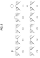
- FIG. 5 shows how ink droplets are jetted from the nozzle opening. More specifically, parts (a) through (e) of FIG. 5 show the jetting of the first ink droplet, and parts (f) through (j) of FIG. 5 show the jetting of second ink droplet.
- part (a) of FIG. 5 corresponds to the time instant (I) in FIG. 4; part (b), to the time instant (II) in FIG. 4; part (c), to the time instant (III) in FIG. 4; part (d) to the time instant (IV) in FIG. 4; part (f), to the time instant (V) in FIG. 4; part (g), to the time instant (VI) in FIG. 4; part (h), to the time instant (VII) in FIG. 4; and part (i), to the time instant (VIII) in FIG. 4.
- the first drive signal is high in maximum voltage value, and therefore the pressure generating chamber is expanded to a large volume, whereby the quantity of ink flowing into the pressure generating chamber 9 from the common ink chamber 11 is large (part (b) of FIG. 5).
- the second voltage waveform forming period is long, so that, after the meniscus 40 is sufficiently restored (part (c) of FIG. 4), the positive pressure is generated. Hence, a large ink droplet can be formed (parts (d) and (e) of FIG. 5).
- the second drive signal is small in maximum voltage value, and therefore although the pressure generating chamber is expanded, the quantity of ink flowing into the pressure generating chamber 9 from the common ink chamber is small (part (g) of FIG. 5).
- the fifth voltage waveform forming period is short.
- the pressure generating chamber 9 is contracted, to generate a positive pressure.
- a small ink droplet can be formed (the parts (i) and (j) of FIG. 5).
- the period of time which elapses from the time instant that the meniscus 40 is retracted until it is restored depends on the ink's inherent period (Helmholtz frequency).
- the second drive signal maintaining time should be longer than the period of time required for the restoration of the meniscus, and should be at least 0.9 times the Helmholtz frequency.
- the fifth drive signal maintaining time should be at most 0.4 times the Helmholtz frequency.
- the fifth drive signal maintaining time is zero (0) sec.
- the transistors Q12 and Q14 shown in FIG. 3 may be rendered conductive at the same time, to allow current to penetrate the transistors to damage them.
- the fifth drive signal maintaining time should be set to a value with which no current penetration occurs with the transistors.
- the weight of the first ink droplet is set to the, value with which the recording sheet can be printed, in its entirety, with the ink droplets with no spaces left therebetween.
- the recording dot diameter of the first ink droplet is set to about 70 ⁇ m with the droplet landing accuracy taken into account.
- Printing data is transferred, in a serial mode, from the memory 22 to the shift register 27.
- the printing data is transferred in synchronization with a transfer clock signal with the timing shown in FIG. 4. That is, the printing data for selecting the first drive signal is transferred to the shift register 27 during the period in which the preceding second drive signal is generated, and the printing data for selecting the second drive signal is transferred to the shift register during the period in which the preceding first drive signal is generated.
- the data stored in the shift register 27 is stored in the latch circuit 26 with the aid of a latch signal, and printing signals 25 are applied to the control terminals of the transistors S.
- the printing data is transferred in such a manner that the first and second drive signals are not selected simultaneously within one drive period.
- the drive signals applied to the piezo-electric element 6 there are three cases: in the first case, the first drive signal is applied to the piezo-electric element 6; in the second case, the second drive signal is applied thereto; and in the third case, none of the first and second drive signals is applied thereto.
- the period Df0 is set to a value with which the first ink droplet which is large in weight can be driven continuously and most quickly; that is, it is set to the maximum drive period of the printing head.
- the timing is such that two different size ink droplets are jetted.
- the drive period is not Df0.
- the drive period Df12 is shorter than Df0.
- the second drive signal is applied, and therefore the drive period Df21 is longer than Df0.
- the maximum drive period Df0 is exceeded.
- the ink jetting characteristic is not affected thereby because of the following reason:
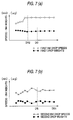
- FIG. 7(a) is a graphical representation indicating first ink drop speeds and weights with drive time intervals which elapse from the application of the second drive signals until the first drive signals are applied, respectively.
- FIG. 7(b) is a graphical representation indicating second ink drop speeds and weights with drive time intervals which elapse from the application of the first drive signals until the second drive signals are applied, respectively.
- the drive period is shorter than Df0, the characteristic is maintained unchanged. This is due to the fact that the time required for eliminating the residual oscillation of the meniscus after the ink has been jetted is variable.
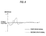
- FIG. 8 is a graphical representation indicating the residual oscillation of the meniscus. More specifically, FIG. 8 shows that, after the application of the first drive signal, the residual oscillation lasts for a relatively long period of time because the ink droplet jetted is relatively heavy; and that, after the application of the second drive signal, the residual osciliation is eliminated quickly because the ink droplet jetted is relatively light.
- the first drive signals are continuously applied to the piezo-electric element 6, it is impossible to make the drive period shorter than Df0; however, if the weight of the ink droplet jetted immediately before is smaller than that of the first ink droplet, then the residual oscillation is quickly eliminated, and therefore it is possible to temporarily make the drive period shorter than Df0.
- the printing speed is higher than that with the conventional one.
- the period of time which elapses from the time instant that the first drive signal is applied to the piezo-electric element 6 until the second drive signal is applied thereto is sufficiently long, which makes it possible to stably jet a small ink droplet.
- the first ink droplet was 0.027 ⁇ g in size
- the second ink droplet was 0.009 ⁇ g in size
- the dot recorded with the first ink droplet was 70 ⁇ m
- the dot recorded with the second ink droplet was 40 ⁇ m.
- the second drive signal is applied to jet a relatively small size ink droplet, and one of the first and second drive signals is selected according to a given density signal.
- ink droplets having different sizes can be jetted from the same nozzle without changing the drive frequency.
Landscapes
- Particle Formation And Scattering Control In Inkjet Printers (AREA)
Claims (7)
- Tintenstrahldruckkopf-Antriebsvorrichtung mit einem piezoelektrischen Element (6) und einer Druckerzeugungskammer (9), welche durch das piezoelektrische Element (6) ausdehnbar und zusammenziehbar ist, um Tintentröpfchen aus einer Düsenöffnung (2) auszustoßen, wobei die Antriebsvorrichtung folgendes umfaßt:einen Antriebssignalerzeugungskreis (23) zum Ausgeben eines ersten Antriebssignals innerhalb einer Druckperiode zum Ausstoß eines relativ großen Tintentröpfchens aus der Düsenöffnung (2) und eines zweiten Antriebssignals nachfolgend auf das erste Drucksignal zum Ausstoß eines relativ kleinen Tintentröpfchens aus der Düsenöffnung (2); undeinen Auswahlkreis zum Auswählen eines der Signale ausgewählt aus dem ersten und dem zweiten Antriebssignal und Anlegen des so gewählten Antriebssignals an das piezoelektrische Element (6).
- Antriebsvorrichtung gemäß Anspruch 1, bei der das erste Antriebssignal folgendes umfaßt:eine erste Spannungswellenform zum Ausdehnen der Druckerzeugungskammer,eine zweite Spannungswellenform zum Aufrecherhalten der Druckerzeugungskammer in einem ausgedehnten Zustand, undeine dritte Spannungswellenform zum Zusammenziehen der Druckerzeugungskammer, und/oder wobei
das zweite Antriebssignal folgendes umfaßt:eine vierte Spannungswellenform zum Ausdehnen der Druckerzeugungskammer;eine fünfte Spannungswellenform zum Aufrecherhalten der Druckerzeugungskammer in einem ausgedehnten Zustand; undeine sechste Spannungswellenform zum Zusammenziehen der Druckerzeugungskammer. - Antriebsvorrichtung gemäß Anspruch 2, bei der eine Zeit des Anlegens der ersten Spannungswellenform kürzer als eine Zeit des Anlegens der vierten Spannungswellenform ist.
- Antriebsvorrichtung gemäß Anspruch 2 oder 3, bei der eine Zeit des Anlegens der zweiten Spannungswellenform länger als eine Zeit des Anlegens der fünften Spannungswellenform ist.
- Antriebsvorrichtung gemäß einem der Ansprüche 2 bis 4, bei der die zweite Spannungswellenform eine höhere Spannung als die fünfte Spannungswellenform aufweist.
- Antriebsvorrichtung gemäß einem der Ansprüche 2 bis 5, bei der eine Periode, über welche die zweite Spannungswellenform aufrechterhalten ist, mindestens etwa das 0,9fache einer Helmholtz-Frequenz von durch den Druckkopf ausgestoßener Tinte beträgt.
- Antriebsvorrichtung gemäß einem der Ansprüche 2 bis 6, bei der eine Periode, über welche die fünfte Spannungswellenform aufrechterhalten ist, nicht mehr als etwa das 0,4fache einer Helmholtz-Frequenz von durch den Druckkopf ausgestoßener Tinte beträgt.
Applications Claiming Priority (6)
| Application Number | Priority Date | Filing Date | Title |
|---|---|---|---|
| JP9401195 | 1995-04-19 | ||
| JP9401195 | 1995-04-19 | ||
| JP94011/95 | 1995-04-19 | ||
| JP57949/96 | 1996-03-14 | ||
| JP5794996 | 1996-03-14 | ||
| JP05794996A JP3156583B2 (ja) | 1995-04-19 | 1996-03-14 | インクジェット式印字ヘッドの駆動装置 |
Publications (3)
| Publication Number | Publication Date |
|---|---|
| EP0738598A2 EP0738598A2 (de) | 1996-10-23 |
| EP0738598A3 EP0738598A3 (de) | 1997-07-09 |
| EP0738598B1 true EP0738598B1 (de) | 1999-08-25 |
Family
ID=26399040
Family Applications (1)
| Application Number | Title | Priority Date | Filing Date |
|---|---|---|---|
| EP96106138A Expired - Lifetime EP0738598B1 (de) | 1995-04-19 | 1996-04-18 | Antriebsvorrichtung zur Erzeugung eines Strahles von Tintentröpfchen |
Country Status (4)
| Country | Link |
|---|---|
| US (1) | US5980015A (de) |
| EP (1) | EP0738598B1 (de) |
| JP (1) | JP3156583B2 (de) |
| DE (1) | DE69603899T2 (de) |
Families Citing this family (29)
| Publication number | Priority date | Publication date | Assignee | Title |
|---|---|---|---|---|
| JP2000516872A (ja) * | 1996-08-27 | 2000-12-19 | トパーズ・テクノロジーズ・インコーポレイテッド | 可変体積のインク滴を生成するインクジェットプリントヘッド |
| EP1332876B1 (de) | 1996-09-09 | 2006-03-22 | Seiko Epson Corporation | Tintenstrahldrucker und Druckverfahren |
| JP3465526B2 (ja) * | 1997-04-10 | 2003-11-10 | ミノルタ株式会社 | インクジェット記録装置およびその制御方法 |
| EP0916505B1 (de) * | 1997-04-16 | 2003-12-03 | Seiko Epson Corporation | Verfahren zum antreiben eines tintenstrahlaufzeichnungskopfes |
| JP2947237B2 (ja) * | 1997-08-18 | 1999-09-13 | 日本電気株式会社 | 画像記録装置 |
| JP4491907B2 (ja) * | 2000-04-26 | 2010-06-30 | ブラザー工業株式会社 | インク滴噴射方法およびその制御装置並びに記憶媒体 |
| CA2267921A1 (en) * | 1998-04-02 | 1999-10-02 | Nec Corporation | Ink-jet print head, driving method thereof and ink-jet printer using the same |
| US6305773B1 (en) * | 1998-07-29 | 2001-10-23 | Xerox Corporation | Apparatus and method for drop size modulated ink jet printing |
| JP3309806B2 (ja) * | 1998-07-31 | 2002-07-29 | 富士通株式会社 | インクジェット記録装置及びインクジェット記録方法 |
| JP3730024B2 (ja) | 1998-08-12 | 2005-12-21 | セイコーエプソン株式会社 | インクジェット式記録ヘッドの駆動装置および駆動方法 |
| US6575564B1 (en) * | 1998-09-30 | 2003-06-10 | Dai Nippon Printing Co., Ltd. | Ink jet recording method using high viscous substance and apparatus for carrying out the same |
| JP2001150672A (ja) * | 1999-01-29 | 2001-06-05 | Seiko Epson Corp | インクジェット式記録装置、及び、インクジェット式記録ヘッドの駆動方法 |
| DE60031316T2 (de) * | 1999-01-29 | 2007-04-12 | Seiko Epson Corp. | Tintenstrahlaufzeichnungsvorrichtung |
| JP2000318153A (ja) * | 1999-05-06 | 2000-11-21 | Nec Corp | インクジェット記録ヘッドの駆動装置及び駆動方法 |
| US6517267B1 (en) | 1999-08-23 | 2003-02-11 | Seiko Epson Corporation | Printing process using a plurality of drive signal types |
| US6629739B2 (en) * | 1999-12-17 | 2003-10-07 | Xerox Corporation | Apparatus and method for drop size switching in ink jet printing |
| JP2001260358A (ja) * | 2000-03-17 | 2001-09-25 | Nec Corp | インクジェット記録ヘッドの駆動装置及びその方法 |
| JP2002103620A (ja) | 2000-07-24 | 2002-04-09 | Seiko Epson Corp | インクジェット式記録装置、及び、インクジェット式記録ヘッドの駆動方法 |
| US6969138B2 (en) * | 2002-08-22 | 2005-11-29 | Matsushita Electric Industrial Co., Ltd. | Ink jet recording apparatus |
| US6913345B2 (en) * | 2003-03-21 | 2005-07-05 | Lexmark International, Inc. | Method and apparatus for firing nozzles in an ink jet printer |
| US7281778B2 (en) | 2004-03-15 | 2007-10-16 | Fujifilm Dimatix, Inc. | High frequency droplet ejection device and method |
| US8491076B2 (en) | 2004-03-15 | 2013-07-23 | Fujifilm Dimatix, Inc. | Fluid droplet ejection devices and methods |
| EP1836056B1 (de) | 2004-12-30 | 2018-11-07 | Fujifilm Dimatix, Inc. | Tintenstrahldruck |
| JP5059336B2 (ja) | 2006-03-30 | 2012-10-24 | ブラザー工業株式会社 | インクジェット記録装置及びその制御条件の決定方法 |
| JP4313388B2 (ja) * | 2006-10-11 | 2009-08-12 | 東芝テック株式会社 | インクジェット記録装置の駆動方法および駆動装置 |
| US7988247B2 (en) | 2007-01-11 | 2011-08-02 | Fujifilm Dimatix, Inc. | Ejection of drops having variable drop size from an ink jet printer |
| JP2009031390A (ja) * | 2007-07-25 | 2009-02-12 | Seiko Epson Corp | 液状体の吐出方法、カラーフィルタの製造方法、有機el素子の製造方法 |
| US8393702B2 (en) | 2009-12-10 | 2013-03-12 | Fujifilm Corporation | Separation of drive pulses for fluid ejector |
| JP7131331B2 (ja) * | 2018-11-22 | 2022-09-06 | セイコーエプソン株式会社 | 駆動回路、集積回路、及び液体吐出装置 |
Family Cites Families (15)
| Publication number | Priority date | Publication date | Assignee | Title |
|---|---|---|---|---|
| JPS5517589A (en) * | 1978-07-27 | 1980-02-07 | Seiko Epson Corp | Ink jet driving method for ink jet recording device |
| US4463359A (en) * | 1979-04-02 | 1984-07-31 | Canon Kabushiki Kaisha | Droplet generating method and apparatus thereof |
| US4459601A (en) * | 1981-01-30 | 1984-07-10 | Exxon Research And Engineering Co. | Ink jet method and apparatus |
| US5285215A (en) * | 1982-12-27 | 1994-02-08 | Exxon Research And Engineering Company | Ink jet apparatus and method of operation |
| US4714935A (en) * | 1983-05-18 | 1987-12-22 | Canon Kabushiki Kaisha | Ink-jet head driving circuit |
| JPS59218866A (ja) * | 1983-05-27 | 1984-12-10 | Canon Inc | 記録装置 |
| JPS6062779A (ja) * | 1983-08-31 | 1985-04-10 | Nec Corp | インクジェット記録方法 |
| US4710784A (en) * | 1985-07-11 | 1987-12-01 | Tokyo Electric Co., Ltd. | Ink jet printing device |
| JPS63182153A (ja) * | 1987-01-24 | 1988-07-27 | Hitachi Ltd | インクジエツト記録装置 |
| JPH01101160A (ja) * | 1987-10-15 | 1989-04-19 | Ricoh Co Ltd | オンデマンド型インクジェットヘッドの駆動方法 |
| GB8829567D0 (en) * | 1988-12-19 | 1989-02-08 | Am Int | Method of operating pulsed droplet deposition apparatus |
| DE69016396T2 (de) * | 1990-01-08 | 1995-05-18 | Tektronix Inc | Verfahren und Gerät zum Drucken mit in der Grösse veränderbaren Tintentropfen unter Verwendung eines auf Anforderung reagierenden Tintenstrahl-Druckkopfes. |
| JPH0415735A (ja) * | 1990-05-02 | 1992-01-21 | Mitsubishi Electric Corp | バッファ管理方式 |
| JP3237685B2 (ja) * | 1992-11-05 | 2001-12-10 | セイコーエプソン株式会社 | インクジェット式記録装置 |
| JP3292223B2 (ja) * | 1993-01-25 | 2002-06-17 | セイコーエプソン株式会社 | インクジェット式記録ヘッドの駆動方法、及びその装置 |
-
1996
- 1996-03-14 JP JP05794996A patent/JP3156583B2/ja not_active Expired - Lifetime
- 1996-04-18 EP EP96106138A patent/EP0738598B1/de not_active Expired - Lifetime
- 1996-04-18 DE DE69603899T patent/DE69603899T2/de not_active Expired - Lifetime
- 1996-04-18 US US08/634,381 patent/US5980015A/en not_active Expired - Lifetime
Also Published As
| Publication number | Publication date |
|---|---|
| DE69603899T2 (de) | 2000-07-20 |
| JP3156583B2 (ja) | 2001-04-16 |
| JPH091798A (ja) | 1997-01-07 |
| DE69603899D1 (de) | 1999-09-30 |
| EP0738598A3 (de) | 1997-07-09 |
| EP0738598A2 (de) | 1996-10-23 |
| US5980015A (en) | 1999-11-09 |
Similar Documents
| Publication | Publication Date | Title |
|---|---|---|
| EP0738598B1 (de) | Antriebsvorrichtung zur Erzeugung eines Strahles von Tintentröpfchen | |
| US6312077B1 (en) | Ink jet printer and ink jet printing method | |
| EP1186410B1 (de) | Tintenstrahlaufzeichnungsgerät und Ansteuerungsverfahren dafür | |
| US5790139A (en) | Ink jet printing apparatus which utilizes different voltages applied to different groups of ejecting members in accordance with image data | |
| US6494554B1 (en) | Apparatus and method for driving recording head for ink-jet printer | |
| JP3309806B2 (ja) | インクジェット記録装置及びインクジェット記録方法 | |
| JP3513986B2 (ja) | インクジェット記録ヘッドの駆動装置及び駆動方法 | |
| JPH1158704A (ja) | インクジェット記録装置 | |
| JP2007022073A (ja) | インクジェットヘッドの駆動方法及び駆動装置 | |
| US6273538B1 (en) | Method of driving ink-jet head | |
| US7802864B2 (en) | Driving method and driving device of inkjet head | |
| JPH09174883A (ja) | インクジェット記録ヘッドの駆動装置 | |
| JP3525011B2 (ja) | インクジェット記録ヘッドの駆動方法 | |
| JP2889377B2 (ja) | インクジェットヘッドの駆動回路およびその駆動方法 | |
| US8702188B2 (en) | Device and method for driving liquid-drop ejection head and image forming apparatus | |
| JP2006088428A (ja) | 液体吐出ヘッドの駆動装置 | |
| JPH08187852A (ja) | インクジェット式記録装置 | |
| JP3322276B2 (ja) | インクジェット式記録ヘッドの駆動方法、及びその装置 | |
| JP2008114486A (ja) | 液体噴射装置、及び、その制御方法 | |
| JP3546929B2 (ja) | インクジェット式記録ヘッドの駆動方法、及びインクジェット式記録装置 | |
| JP4039038B2 (ja) | インクジェット式記録装置、及び、記録ヘッドの駆動方法 | |
| JP3892622B2 (ja) | インクジェット記録ヘッドの駆動方法及び駆動装置 | |
| JP3346075B2 (ja) | インクジェットヘッドの駆動方法 | |
| JP3329354B2 (ja) | インクジェット式記録ヘッドの駆動回路及び駆動方法 | |
| JP2000263775A (ja) | インクジェット式記録装置 |
Legal Events
| Date | Code | Title | Description |
|---|---|---|---|
| PUAI | Public reference made under article 153(3) epc to a published international application that has entered the european phase |
Free format text: ORIGINAL CODE: 0009012 |
|
| AK | Designated contracting states |
Kind code of ref document: A2 Designated state(s): DE FR GB |
|
| PUAL | Search report despatched |
Free format text: ORIGINAL CODE: 0009013 |
|
| AK | Designated contracting states |
Kind code of ref document: A3 Designated state(s): DE FR GB |
|
| 17P | Request for examination filed |
Effective date: 19970722 |
|
| 17Q | First examination report despatched |
Effective date: 19980702 |
|
| GRAG | Despatch of communication of intention to grant |
Free format text: ORIGINAL CODE: EPIDOS AGRA |
|
| GRAG | Despatch of communication of intention to grant |
Free format text: ORIGINAL CODE: EPIDOS AGRA |
|
| GRAG | Despatch of communication of intention to grant |
Free format text: ORIGINAL CODE: EPIDOS AGRA |
|
| GRAH | Despatch of communication of intention to grant a patent |
Free format text: ORIGINAL CODE: EPIDOS IGRA |
|
| GRAH | Despatch of communication of intention to grant a patent |
Free format text: ORIGINAL CODE: EPIDOS IGRA |
|
| GRAA | (expected) grant |
Free format text: ORIGINAL CODE: 0009210 |
|
| AK | Designated contracting states |
Kind code of ref document: B1 Designated state(s): DE FR GB |
|
| REF | Corresponds to: |
Ref document number: 69603899 Country of ref document: DE Date of ref document: 19990930 |
|
| ET | Fr: translation filed | ||
| PLBE | No opposition filed within time limit |
Free format text: ORIGINAL CODE: 0009261 |
|
| STAA | Information on the status of an ep patent application or granted ep patent |
Free format text: STATUS: NO OPPOSITION FILED WITHIN TIME LIMIT |
|
| 26N | No opposition filed | ||
| REG | Reference to a national code |
Ref country code: GB Ref legal event code: IF02 |
|
| REG | Reference to a national code |
Ref country code: FR Ref legal event code: PLFP Year of fee payment: 20 |
|
| PGFP | Annual fee paid to national office [announced via postgrant information from national office to epo] |
Ref country code: GB Payment date: 20150415 Year of fee payment: 20 Ref country code: DE Payment date: 20150414 Year of fee payment: 20 |
|
| PGFP | Annual fee paid to national office [announced via postgrant information from national office to epo] |
Ref country code: FR Payment date: 20150408 Year of fee payment: 20 |
|
| REG | Reference to a national code |
Ref country code: DE Ref legal event code: R071 Ref document number: 69603899 Country of ref document: DE |
|
| REG | Reference to a national code |
Ref country code: GB Ref legal event code: PE20 Expiry date: 20160417 |
|
| PG25 | Lapsed in a contracting state [announced via postgrant information from national office to epo] |
Ref country code: GB Free format text: LAPSE BECAUSE OF EXPIRATION OF PROTECTION Effective date: 20160417 |