EP0738821A2 - Verdunkelungs-/Verschattungsvorrichtung - Google Patents
Verdunkelungs-/Verschattungsvorrichtung Download PDFInfo
- Publication number
- EP0738821A2 EP0738821A2 EP96105079A EP96105079A EP0738821A2 EP 0738821 A2 EP0738821 A2 EP 0738821A2 EP 96105079 A EP96105079 A EP 96105079A EP 96105079 A EP96105079 A EP 96105079A EP 0738821 A2 EP0738821 A2 EP 0738821A2
- Authority
- EP
- European Patent Office
- Prior art keywords
- receptacle
- blind
- roller shutter
- darkening
- inspection panel
- Prior art date
- Legal status (The legal status is an assumption and is not a legal conclusion. Google has not performed a legal analysis and makes no representation as to the accuracy of the status listed.)
- Granted
Links
Images

Classifications
-
- E—FIXED CONSTRUCTIONS
- E06—DOORS, WINDOWS, SHUTTERS, OR ROLLER BLINDS IN GENERAL; LADDERS
- E06B—FIXED OR MOVABLE CLOSURES FOR OPENINGS IN BUILDINGS, VEHICLES, FENCES OR LIKE ENCLOSURES IN GENERAL, e.g. DOORS, WINDOWS, BLINDS, GATES
- E06B9/00—Screening or protective devices for wall or similar openings, with or without operating or securing mechanisms; Closures of similar construction
- E06B9/02—Shutters, movable grilles, or other safety closing devices, e.g. against burglary
- E06B9/08—Roll-type closures
- E06B9/11—Roller shutters
- E06B9/17—Parts or details of roller shutters, e.g. suspension devices, shutter boxes, wicket doors, ventilation openings
- E06B9/17007—Shutter boxes; Details or component parts thereof
- E06B9/17023—Shutter boxes; Details or component parts thereof made of more than two pieces
-
- E—FIXED CONSTRUCTIONS
- E06—DOORS, WINDOWS, SHUTTERS, OR ROLLER BLINDS IN GENERAL; LADDERS
- E06B—FIXED OR MOVABLE CLOSURES FOR OPENINGS IN BUILDINGS, VEHICLES, FENCES OR LIKE ENCLOSURES IN GENERAL, e.g. DOORS, WINDOWS, BLINDS, GATES
- E06B9/00—Screening or protective devices for wall or similar openings, with or without operating or securing mechanisms; Closures of similar construction
- E06B9/24—Screens or other constructions affording protection against light, especially against sunshine; Similar screens for privacy or appearance; Slat blinds
- E06B9/26—Lamellar or like blinds, e.g. venetian blinds
- E06B9/264—Combinations of lamellar blinds with roller shutters, screen windows, windows, or double panes; Lamellar blinds with special devices
Definitions
- the present invention relates to a darkening or shading device for a window or the like.
- a blackout or shading device in particular a roller blind, venetian blind or slatted blind, to the inside of a window or the like means that space near the top of the window is used or taken up by suitable holding devices, for example for a spring roller blind a non-lowered venetian blind or louvre blind affects the transparent window surface.
- brackets are arranged on the sides of a window in the vicinity of its upper limit for attaching a spring roller blind, these brackets serving as bearings for a shaft around which the spring roller blind can be wound.
- brackets are attached either to the window frame or to the adjacent masonry, with the result that the Window frames or support elements protruding from the masonry with a shaft attached between them impair the upper window area.
- a louvre or Roman blind is to be attached, no such arrangement consisting of brackets and shaft is required.
- a slatted or Roman blind like a spring roller blind, does not occupy a space at the top of the window, so that the transparent window area is generally reduced.
- the transparent window area is not or only insignificantly reduced.
- the receptacle for the darkening device is closed off from the roller shutter armor box.
- no dirt particles from the roller shutter curtain, which is exposed to the weather, can get onto the darkening device, which is arranged on the inside of a window.
- insects that have entered the roller shutter curtain casing from the outside of the building via an inlet funnel of the roller shutter curtain cannot reach the living space via an opening in the receptacle for guiding the darkening device. It is also through the structural separation of the receptacle for the darkening or shading device from the receptacle for the roller shutter curtain better thermal insulation of the interior of the room from the outside is present, since this arrangement prevents cold air from entering the room from the outside.
- the receptacle for the darkening or shading device is arranged detachably on the roller shutter armor box.
- the receptacle for the blackout device is particularly preferably integrated into the inspection panel.
- this inspection panel is pivotally arranged, so that the darkening device is easily replaceable and maintainable.
- a spring roller blind can be used as the darkening device, in which case there is a slit-shaped opening on the underside of the receptacle of the spring roller blind through which the spring roller blind can be guided.
- a slatted blind is provided as the darkening device, in which case there is a larger opening on the underside of the receptacle than in the case of a spring roller blind in order to lead the slatted blind out of the receptacle.
- a Roman shade can be used as the darkening device, in which case, as in the case of a slatted blind, there is a larger opening on the underside of the receptacle.
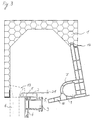
- a revision screen 16 is arranged on the underside of a roller shutter armor box 1, which can accommodate a spring roller blind 12.
- the spring roller blind 12 can be guided out of the inspection panel 16 through a gap-shaped opening 15 on the underside.
- a receptacle 7 for the spring roller blind 12 is integrated in the inspection panel 16, which is formed by a hollow chamber profile.
- the receptacle 7 is of cylindrical shape and extends parallel to a roller shutter armor box 1 along the top of a window.
- a shaft 17 In the middle of the roller shutter curtain case 1 there is a shaft 17 on which a roller shutter curtain 11 is mounted.
- the roller shutter curtain 11 can be guided out of the roller shutter curtain case 1 via an inlet funnel 13, a rail 6 being provided for further guiding the roller shutter curtain 11.
- the inlet funnel 13 is arranged between an outer wall of the roller shutter armor box 1 and a connection profile 2.
- the rail 6 is arranged on the underside of the inlet funnel 13.
- the connection profile 2 has a locking groove or locking rib 8 on the underside, on which a window frame profile 3 can be locked.
- the window frame profile 3 has a rollover 4 on the side facing outwards.
- a support device 5 is arranged on the upper side thereof, on which the inspection panel 16 is supported.
- the inspection panel 16 is arranged in the direction of the inside of the room next to the connection profile 2.
- the hollow chamber profile of the inspection panel 16 has support rods 9 which space opposite walls of the inspection panel 16.
- the receptacle 7 integrated into the inspection panel 16 is arranged in the roller shutter curtain case 1 in such a way that even when the roller shutter curtain 11 is wound up, none Points of contact of the inspection panel 16 with the roller shutter curtain 11 are present.
- the receptacle 7 is located on the underside of the roller shutter armor box 1 and is arranged next to the side wall of the roller shutter armor box 1 facing the inside of the room.
- the inspection panel 16 can also be formed from a foam profile 10.
- a slatted blind 18 is received by the inspection panel 16.
- the receptacle 7 has an opening 20 on the underside which is larger than the opening 15 of the receptacle 7 of the spring roller blind 12 in order to lead the slatted roller blind 18 out of the receptacle 7.
- the receptacle 7 essentially has the shape of a "U" which is open at the bottom. In the non-lowered state, the slatted roller blind 18 does not protrude, or protrudes only slightly, from the opening 20 of the receptacle 7.
- this arrangement can also accommodate a Roman blind (not shown).
- Fig. 3 shows a receptacle 7, which is received in a guide 14.
- the guide 14 is arranged on the lower boundary of the side wall of the roller shutter armor box 1 facing the inside of the room.
- the receptacle 7 is integrated in the removable inspection panel 16.
- the inspection panel 16 can be pivoted toward the inside of the room.
- the guide 14 is formed by a recess in the lower end face of the side wall of the roller shutter box, into which the inspection panel 16 can be inserted obliquely from below. For oblique insertion, the projection of the inspection panel 16 to be inserted is somewhat tapered towards its end. After the inspection panel 16 has been opened, it can be removed from the roller shutter armor box 1.
- the inspection panel 16 can be attached to the connection profile 2 by means of a suitable locking device 21, for example by means of a screw.
Landscapes
- Engineering & Computer Science (AREA)
- Structural Engineering (AREA)
- Architecture (AREA)
- Civil Engineering (AREA)
- Operating, Guiding And Securing Of Roll- Type Closing Members (AREA)
- Non-Portable Lighting Devices Or Systems Thereof (AREA)
- Finger-Pressure Massage (AREA)
Abstract
Description
- Die vorliegende Erfindung betrifft eine Verdunkelungs- bzw. Verschattungsvorrichtung für ein Fenster oder dergleichen.
- Das Anbringen einer Verdunkelungs- bzw. Verschattungsvorrichtung, insbesondere eines Spring-, Raff- oder Lamellenrollos, an der Rauminnenseite eines Fensters oder dergleichen hat zur Folge, daß in der Nähe der Fensteroberseite Platz durch geeignete Haltevorrichtungen, zum Beispiel für ein Springrollo, beansprucht wird bzw. ein nicht herabgelassenes Raff- oder Lamellenrollo die transparente Fensterfläche beeinträchtigt.
- Üblicherweise werden zum Anbringen eines Springrollos Halterungen an den Seiten eines Fensters in der Nähe dessen oberer Begrenzung angeordnet, wobei diese Halterungen als Lagerung für eine Welle dienen, um die das Springrollo aufgewikkelt werden kann.
- Ein Nachteil dieser Anordnung ist, daß die Halterungen entweder am Fensterrahmen oder am daran angrenzenden Mauerwerk angebracht werden, was zur Folge hat, daß vom Fensterrahmen bzw. vom Mauerwerk hervorstehende Halterungselemente mit einer dazwischen angebrachten Welle den oberen Fensterbereich beeinträchtigen.
- Soll zum Beispiel ein Lamellen- oder ein Raffrollo angebracht werden, so ist keine solche Anordnung bestehend aus Halterungen und Welle erforderlich. Ein Lamellen- bzw. Raffrollo beansprucht jedoch im nicht herabgelassenen Zustand, ebenso wie ein Springrollo, einen Raum an der Oberseite des Fensters, so daß die transparente Fensterfläche im allgemeinen reduziert wird.
- Diese Anordnungen haben den Nachteil, daß sie an der Oberseite des Fensters Platz beanspruchen, so daß nicht die ganze für transparente Fensterfläche verfügbare Fläche verringert wird.
- Es ist die Aufgabe der Erfindung, eine Aufnahme für eine Verdunkelungs- bzw. Verschattungsvorrichtung so anzuordnen, daß die transparente Fensterfläche nicht beeinträchtigt wird.
- Diese Aufgabe wird durch den Gegenstand von Anspruch 1 gelöst.
- Die Unteransprüche sind auf zweckmäßige Ausführungsformen der Erfindung gerichtet.
- Durch die erfindungsgemäße Anordnung der Aufnahme für die Verdunkelungs- bzw. Verschattungsvorrichtung entsprechend Anspruch 1 wird die transparente Fensterfläche gar nicht oder nur unwesentlich reduziert.
- In einer bevorzugten Ausführungsform ist die Aufnahme für die Verdunkelungsvorrichtung gegenüber dem Rolladenpanzerkasten abgeschlossen. Dadurch können keine Schmutzpartikel vom Rolladenpanzer, der den Wettereinflüssen ausgesetzt ist, auf die Verdunkelungsvorrichtung, die an der Rauminnenseite eines Fensters angeordnet ist, gelangen. Desweiteren können Insekten, die von der Gebäudeaußenseite über einen Einlauftrichter des Rolladenpanzers in den Rolladenpanzerkasten gelangt sind, nicht über eine Öffnung der Aufnahme zur Führung der Verdunkelungsvorrichtung in den Wohnraum gelangen. Außerdem ist durch die bauliche Trennung der Aufnahme für die Verdunkelungs- oder Verschattungsvorrichtung von der Aufnahme für den Rolladenpanzer eine bessere Wärmeisolierung des Rauminneren von der Außenseite vorhanden, da durch diese Anordnung keine kalte Luft von der Außenseite in den Raum gelangen kann.
- In einer weiteren bevorzugten Ausführungsform ist die Aufnahme für die Verdunkelungs- oder Verschattungsvorrichtung abnehmbar am Rolladenpanzerkasten angeordnet.
- Besonders bevorzugt ist die Aufnahme für die Verdunkelungsvorrichtung in die Revisionsblende integriert. In einer weiteren bevorzugten Ausführungsform ist diese Revisionsblende schwenkbar angeordnet, so daß die Verdunkelungsvorrichtung leicht austauschbar und wartbar ist.
- Als Verdunkelungsvorrichtung kann ein Springrollo verwendet werden, wobei dann an der Unterseite der Aufnahme des Springrollos eine schlitzförmige Öffnung vorhanden ist, durch die das Springrollo geführt werden kann.
- In einer alternativen Ausführungsform ist als Verdunkelungsvorrichtung ein Lamellenrollo vorgesehen, wobei sich dann an der Unterseite der Aufnahme eine größere Öffnung befindet als bei einem Springrollo, um das Lamellenrollo aus der Aufnahme herauszuführen.
- Als weitere alternative Ausführungsform kann als Verdunkelungsvorrichtung ein Raffrollo verwendet werden, wobei dann, wie bei einem Lamellenrollo, eine größere Öffnung an der Unterseite der Aufnahme vorhanden ist.
- Die Erfindung wird anhand einer bevorzugten Ausführungsform unter Bezugnahme auf die nachstehenden Zeichnungen im einzelnen erläutert:
- Fig. 1
- zeigt einen vertikalen Schnitt durch eine erfindungsgemäße Anordnung einer Aufnahme für ein Springrollo, wobei die Revisionsblende durch ein Hohlkammerprofil gebildet wird;
- Fig. 2
- zeigt einen vertikalen Schnitt durch eine erfindungsgemäße Anordnung einer Aufnahme für ein Lamellenrollo oder Raffrollo, wobei die Revisionsblende durch ein Schaumprofil gebildet wird;
- Fig. 3
- zeigt einen vertikalen Schnitt durch eine erfindungsgemäße Anordnung einer Aufnahme für eine Verdunkelungsvorrichtung, wobei die in die Revisionsblende integrierte Aufnahme für ein Springrollo schwenkbar angeordnet ist und abgenommen werden kann.
- Wie Fig. 1 zeigt, ist an der Unterseite eines Rolladenpanzerkastens 1 eine Revisionsblende 16 angeordnet, die ein Springrollo 12 aufnehmen kann. Das Springrollo 12 kann durch eine spaltförmige Öffnung 15 an der Unterseite der Revisionsblende 16 aus dieser herausgeführt werden. In die Revisionsblende 16, die durch ein Hohlkammerprofil gebildet wird, ist eine Aufnahme 7 für das Springrollo 12 integriert. Die Aufnahme 7 ist von zylinderförmiger Gestalt und erstreckt sich parallel zu einem Rolladenpanzerkasten 1 längs der Oberseite eines Fensters. An der Unterseite der der Rauminnenseite zugewandten Seitenwand des Rollladenpanzerkastens 1 befindet sich eine Ausnehmung 19, in die die Revisionsblende 16 hineinragt. In der Mitte des Rolladenpanzerkastens 1 ist eine Welle 17 angeordnet, auf der ein Rolladenpanzer 11 gelagert ist. Der Rolladenpanzer 11 kann über einen Einlauftrichter 13 aus dem Rolladenpanzerkasten 1 geführt werden, wobei eine Schiene 6 zur weiteren Führung des Rolladenpanzers 11 vorhanden ist. Der Einlauftrichter 13 ist zwischen einer Außenwand des Rolladenpanzerkastens 1 und einem Anschlußprofil 2 angeordnet. An der Unterseite des Einlauftrichters 13 ist die Schiene 6 angeordnet. Das Anschlußprofil 2 weist an der Unterseite ein Rastnut bzw. Rastrippe 8 auf, an der ein Fensterrahmenprofil 3 eingerastet werden kann. Das Fensterrahmenprofil 3 weist an der nach außen weisenden Seite einen Überschlag 4 auf. Auf der zur Rauminnenseite weisenden Seite des Fensterrahmenprofils 3 ist an dessen Oberseite eine Auflagevorrichtung 5 angeordnet, auf der die Revisionsblende 16 aufliegend gelagert ist. Die Revisionsblende 16 ist in Richtung der Rauminnenseite neben dem Anschlußprofil 2 angeordnet. Das Hohlkammerprofil der Revisionsblende 16 weist Stützstäbe 9 auf, die gegenüberliegende Wände der Revisionsblende 16 beabstanden. Die in die Revisionsblende 16 integrierte Aufnahme 7 ist so in dem Rolladenpanzerkasten 1 angeordnet, daß selbst bei aufgewickeltem Rolladenpanzer 11 keine Berührungspunkte der Revisionsblende 16 mit dem Rolladenpanzer 11 vorhanden sind. Die Aufnahme 7 befindet sich an der Unterseite des Rolladenpanzerkastens 1 und ist neben der der Rauminnenseite zugewandten Seitenwand des Rolladenpanzerkastens 1 angeordnet.
- Wie Fig. 2 zeigt, kann die Revisionsblende 16 auch aus einem Schaumprofil 10 ausgebildet sein. Von der Revisionsblende 16 wird gemäß dieser Ausführungsform der Erfindung ein Lamellenrollo 18 aufgenommen. Dabei weist die Aufnahme 7 an der Unterseite eine Öffnung 20 auf, die größer als die Öffnung 15 der Aufnahme 7 des Springrollos 12 ist, um das Lamellenrollo 18 aus der Aufnahme 7 herauszuführen. Die Aufnahme 7 weist in diesem Ausführungsbeispiel im wesentlichen die Form eines nach unten offenen "U" auf. Im nicht herabgelassenen Zustand ragt das Lamellenrollo 18 nicht oder nur wenig aus der Öffnung 20 der Aufnahme 7 heraus. Alternativ zu dem Lamellenrollo 18 kann von dieser Anordnung auch ein Raffrollo (nicht gezeigt) aufgenommen werden.
- Fig. 3 zeigt eine Aufnahme 7, die in einer Führung 14 aufgenommen ist. Die Führung 14 ist an der unteren Begrenzung der der Rauminnenseite zugewandten Seitenwand des Rolladenpanzerkastens 1 angeordnet. Die Aufnahme 7 ist in die abnehmbare Revisionsblende 16 integriert. Die Revisionsblende 16 ist zur Rauminnenseite hin schwenkbar. Die Führung 14 wird durch eine Vertiefung in der unteren Stirnfläche der Seitenwand des Rolladenkastens gebildet, in die die Revisionsblende 16 schräg von unten einführbar ist. Zum schrägen Einführen ist der einzuführende Vorsprung der Revisionsblende 16 zu seinem Ende hin etwas verjüngt. Nach dem Aufklappen der Revisionsblende 16 kann diese vom Rolladenpanzerkasten 1 abgenommen werden. Die Revisionsblende 16 kann mittels einer geeigneten Arretierungsvorrichtung 21, beispielsweise mittels einer Schraube, an dem Anschlußprofil 2 befestigt werden.
Claims (8)
- Aufnahme (7) für eine rauminnenseitige Verdunkelungs- oder Verschattungsvorrichtung (12,18) für ein Fenster oder dergleichen,
dadurch gekennzeichnet, daß
die Aufnahme (7) in einem Kasten (1) für einen Rolladenpanzer (11) angeordnet ist. - Aufnahme nach Anspruch 1, dadurch gekennzeichnet, daß die Aufnahme (7) gegen das Innere des Rolladenkastens (1) abgeschlossen ist.
- Aufnahme nach Anspruch 1 oder 2, dadurch gekennzeichnet, daß die Aufnahme (7) abnehmbar am Rolladenkasten (1) angeordnet ist.
- Aufnahme nach einem der vorhergehenden Ansprüche, dadurch gekennzeichnet, daß die Aufnahme (7) in eine Revisionsblende (16) integriert ist.
- Aufnahme nach einem der vorhergehenden Ansprüche, dadurch gekennzeichnet, daß die Aufnahme (7) durch ein Hohlkammerprofil gebildet wird.
- Aufnahme nach einem der Ansprüche 1 bis 4, dadurch gekennzeichnet, daß die Aufnahme (7) durch ein Schaumprofil gebildet wird.
- Aufnahme nach einem der vorhergehenden Ansprüche, dadurch gekennzeichnet, daß die Aufnahme (7) an ihrer Unterseite eine schlitzartige Öffnung (15) zur Durchführung der als Springrollo (12) ausgebildeten Verdunkelungs- oder Verschattungsvorrichtung aufweist.
- Aufnahme nach einem der vorhergehenden Ansprüche, dadurch gekennzeichnet, daß die Aufnahme (7) an ihrer Unterseite eine Öffnung (20) zur Durchführung der als Lamellenrollo (18) oder Raffrollo ausgebildeten Verdunkelungs- oder Verschattungsvorrichtung aufweist.
Applications Claiming Priority (2)
| Application Number | Priority Date | Filing Date | Title |
|---|---|---|---|
| DE19513925A DE19513925C2 (de) | 1995-04-12 | 1995-04-12 | Zusatzrollo |
| DE19513925 | 1995-04-12 |
Publications (3)
| Publication Number | Publication Date |
|---|---|
| EP0738821A2 true EP0738821A2 (de) | 1996-10-23 |
| EP0738821A3 EP0738821A3 (de) | 1997-04-23 |
| EP0738821B1 EP0738821B1 (de) | 2003-02-19 |
Family
ID=7759581
Family Applications (1)
| Application Number | Title | Priority Date | Filing Date |
|---|---|---|---|
| EP96105079A Expired - Lifetime EP0738821B1 (de) | 1995-04-12 | 1996-03-29 | Aufnahmekasten zur Aufnahme eines Rolladenpanzers sowie eines Spring-, Lamellen- oder Raffrollos |
Country Status (3)
| Country | Link |
|---|---|
| EP (1) | EP0738821B1 (de) |
| AT (1) | ATE232937T1 (de) |
| DE (2) | DE19513925C2 (de) |
Cited By (3)
| Publication number | Priority date | Publication date | Assignee | Title |
|---|---|---|---|---|
| EP0843067A3 (de) * | 1996-11-13 | 1999-02-17 | Elket Kunststoff-Technik GmbH & Co. KG | Rolladen und alternative Fensterabschirmung aufnehmender Rolladenkasten |
| GB2542330A (en) * | 2015-07-11 | 2017-03-22 | Enviroscreen Systems Llp | Blind box |
| AT519678A4 (de) * | 2017-07-24 | 2018-09-15 | Drutex S A | Rollladenkasten mit dichtungselement |
Families Citing this family (4)
| Publication number | Priority date | Publication date | Assignee | Title |
|---|---|---|---|---|
| DE9413520U1 (de) * | 1994-08-23 | 1994-11-10 | SKS-Stakusit-Kunststoff GmbH & Co. KG, 47198 Duisburg | Fliegengitter-Rollo |
| DE19948468C2 (de) * | 1999-10-08 | 2003-09-11 | Roma Rolladensysteme Gmbh | Aufsatz-Rollladenkasten |
| DE10033784C1 (de) * | 2000-07-12 | 2002-05-29 | Gerald Rankl | Aufnahmekasten für eine Abschattvorrichtung |
| DE202015002897U1 (de) | 2015-04-22 | 2015-06-18 | Michael Stock | Rollladenbehang |
Family Cites Families (5)
| Publication number | Priority date | Publication date | Assignee | Title |
|---|---|---|---|---|
| CH374187A (de) * | 1959-09-10 | 1963-12-31 | Schenker Storen Maschf | Rollstoreneinrichtung |
| SE328113B (de) * | 1963-10-30 | 1970-09-07 | P Persson | |
| FR2151223A5 (de) * | 1971-08-26 | 1973-04-13 | Sere Georges | |
| DE4311415A1 (de) * | 1993-04-07 | 1994-10-13 | Irowi Insektenschutz Rollgitte | Insektenschutz-Rollgittervorrichtung mit Reinigungsbürste |
| DE9413520U1 (de) * | 1994-08-23 | 1994-11-10 | SKS-Stakusit-Kunststoff GmbH & Co. KG, 47198 Duisburg | Fliegengitter-Rollo |
-
1995
- 1995-04-12 DE DE19513925A patent/DE19513925C2/de not_active Expired - Fee Related
-
1996
- 1996-03-29 DE DE59610143T patent/DE59610143D1/de not_active Expired - Fee Related
- 1996-03-29 EP EP96105079A patent/EP0738821B1/de not_active Expired - Lifetime
- 1996-03-29 AT AT96105079T patent/ATE232937T1/de not_active IP Right Cessation
Cited By (4)
| Publication number | Priority date | Publication date | Assignee | Title |
|---|---|---|---|---|
| EP0843067A3 (de) * | 1996-11-13 | 1999-02-17 | Elket Kunststoff-Technik GmbH & Co. KG | Rolladen und alternative Fensterabschirmung aufnehmender Rolladenkasten |
| GB2542330A (en) * | 2015-07-11 | 2017-03-22 | Enviroscreen Systems Llp | Blind box |
| AT519678A4 (de) * | 2017-07-24 | 2018-09-15 | Drutex S A | Rollladenkasten mit dichtungselement |
| AT519678B1 (de) * | 2017-07-24 | 2018-09-15 | Drutex S A | Rollladenkasten mit dichtungselement |
Also Published As
| Publication number | Publication date |
|---|---|
| DE19513925A1 (de) | 1996-10-24 |
| ATE232937T1 (de) | 2003-03-15 |
| EP0738821A3 (de) | 1997-04-23 |
| DE59610143D1 (de) | 2003-03-27 |
| EP0738821B1 (de) | 2003-02-19 |
| DE19513925C2 (de) | 1999-04-01 |
Similar Documents
| Publication | Publication Date | Title |
|---|---|---|
| DE69807438T2 (de) | Universelle befestigungs- und parallelführungsvorrichtung für eine fensterabschirmung | |
| DE8990082U1 (de) | Jalousievorrichtung für ein Fenster in einem geneigten Dach | |
| DE2312661C3 (de) | Faltjalousie | |
| EP0738821A2 (de) | Verdunkelungs-/Verschattungsvorrichtung | |
| DE29622130U1 (de) | Duschabschirmung | |
| DE19626124C2 (de) | Rolladen-Rollo-Kombination | |
| DE69600625T2 (de) | Doppelte abschirmvorrichtung für ein fenster | |
| DE19963919B4 (de) | Verfahren und Einrichtung zum wärmeverlustarmen Belüften von Räumen über eine oder mehrere Fenster/Tür-Rollladenanordnungen | |
| DE3232712A1 (de) | Vorrichtung zum schutz gegen das eindringen von insekten in raeume | |
| CH688560A5 (de) | Rolladenanordnung mit Insektenschutzgitter. | |
| DE202007008114U1 (de) | Lichtschutzkassette für einen Fensterflügel | |
| DE3836595A1 (de) | Vorrichtung zum abdunkeln von fenstern | |
| DE9411372U1 (de) | Lamelle für Lamellenjalousien | |
| EP4446556B1 (de) | Gebäudeöffnungsverschattungsvorrichtung und seitenführungsschiene hierfür | |
| DE3531476A1 (de) | Vorrichtung zum verhindern des eindringens von insekten in raeume | |
| EP0212229A1 (de) | Fenster mit Insektenschutz bzw. Insektenschutz an Fenstern | |
| DE19808624C1 (de) | Fassadenrollo | |
| DE29902982U1 (de) | Staub-, Pollen- und/oder Insektenschutz für Türen und Fenster | |
| AT397413B (de) | Verstellbare abdeckeinrichtung für öffnungen | |
| AT749U1 (de) | Rolladeneinrichtung | |
| DE29700160U1 (de) | Rolladenaggregat mit einem Rolladenkasten, insbesondere Rolladen-Aufsetzkasten, mit einem Rolladenpanzer mit Rolladenendstab und einer Rolladenführung, und mit einem als Springrollo ausgebildeten Fliegengitter-Rollo | |
| DE29501051U1 (de) | Rolladenaggregat | |
| DE202025004042U1 (de) | Zusatzteil für einen Rollladenpanzer oder ein Rollladensystem | |
| DE8603100U1 (de) | Dachentlüftungshaube für mobile Räume wie Wohnwagen und/oder Wohnmobile | |
| DE3639077A1 (de) | Schiebefenster mit aufwickelbarem fliegennetz |
Legal Events
| Date | Code | Title | Description |
|---|---|---|---|
| PUAI | Public reference made under article 153(3) epc to a published international application that has entered the european phase |
Free format text: ORIGINAL CODE: 0009012 |
|
| AK | Designated contracting states |
Kind code of ref document: A2 Designated state(s): AT BE CH DE ES FR GR IT LI LU NL PT |
|
| PUAL | Search report despatched |
Free format text: ORIGINAL CODE: 0009013 |
|
| AK | Designated contracting states |
Kind code of ref document: A3 Designated state(s): AT BE CH DE ES FR GR IT LI LU NL PT |
|
| 17P | Request for examination filed |
Effective date: 19970926 |
|
| RAP1 | Party data changed (applicant data changed or rights of an application transferred) |
Owner name: KOEMMERLING KUNSTSTOFF GMBH |
|
| 17Q | First examination report despatched |
Effective date: 20010405 |
|
| GRAG | Despatch of communication of intention to grant |
Free format text: ORIGINAL CODE: EPIDOS AGRA |
|
| RTI1 | Title (correction) |
Free format text: HOUSING FOR A ROLLER SHUTTER AND A SPRING ROLLER, VENETIAN OR ROMAN BLIND |
|
| RTI1 | Title (correction) |
Free format text: HOUSING FOR A ROLLER SHUTTER AND A SPRING ROLLER, VENETIAN OR ROMAN BLIND |
|
| GRAG | Despatch of communication of intention to grant |
Free format text: ORIGINAL CODE: EPIDOS AGRA |
|
| GRAH | Despatch of communication of intention to grant a patent |
Free format text: ORIGINAL CODE: EPIDOS IGRA |
|
| GRAH | Despatch of communication of intention to grant a patent |
Free format text: ORIGINAL CODE: EPIDOS IGRA |
|
| GRAA | (expected) grant |
Free format text: ORIGINAL CODE: 0009210 |
|
| AK | Designated contracting states |
Designated state(s): AT BE CH DE ES FR GR IT LI LU NL PT |
|
| PG25 | Lapsed in a contracting state [announced via postgrant information from national office to epo] |
Ref country code: NL Free format text: LAPSE BECAUSE OF FAILURE TO SUBMIT A TRANSLATION OF THE DESCRIPTION OR TO PAY THE FEE WITHIN THE PRESCRIBED TIME-LIMIT Effective date: 20030219 Ref country code: IT Free format text: LAPSE BECAUSE OF FAILURE TO SUBMIT A TRANSLATION OF THE DESCRIPTION OR TO PAY THE FEE WITHIN THE PRE;WARNING: LAPSES OF ITALIAN PATENTS WITH EFFECTIVE DATE BEFORE 2007 MAY HAVE OCCURRED AT ANY TIME BEFORE 2007. THE CORRECT EFFECTIVE DATE MAY BE DIFFERENT FROM THE ONE RECORDED.SCRIBED TIME-LIMIT Effective date: 20030219 Ref country code: GR Free format text: LAPSE BECAUSE OF FAILURE TO SUBMIT A TRANSLATION OF THE DESCRIPTION OR TO PAY THE FEE WITHIN THE PRESCRIBED TIME-LIMIT Effective date: 20030219 |
|
| REG | Reference to a national code |
Ref country code: CH Ref legal event code: EP |
|
| REF | Corresponds to: |
Ref document number: 59610143 Country of ref document: DE Date of ref document: 20030327 Kind code of ref document: P |
|
| PG25 | Lapsed in a contracting state [announced via postgrant information from national office to epo] |
Ref country code: LU Free format text: LAPSE BECAUSE OF NON-PAYMENT OF DUE FEES Effective date: 20030329 Ref country code: AT Free format text: LAPSE BECAUSE OF NON-PAYMENT OF DUE FEES Effective date: 20030329 |
|
| PG25 | Lapsed in a contracting state [announced via postgrant information from national office to epo] |
Ref country code: LI Free format text: LAPSE BECAUSE OF NON-PAYMENT OF DUE FEES Effective date: 20030331 Ref country code: CH Free format text: LAPSE BECAUSE OF NON-PAYMENT OF DUE FEES Effective date: 20030331 Ref country code: BE Free format text: LAPSE BECAUSE OF NON-PAYMENT OF DUE FEES Effective date: 20030331 |
|
| PG25 | Lapsed in a contracting state [announced via postgrant information from national office to epo] |
Ref country code: PT Free format text: LAPSE BECAUSE OF FAILURE TO SUBMIT A TRANSLATION OF THE DESCRIPTION OR TO PAY THE FEE WITHIN THE PRESCRIBED TIME-LIMIT Effective date: 20030519 |
|
| NLV1 | Nl: lapsed or annulled due to failure to fulfill the requirements of art. 29p and 29m of the patents act | ||
| PG25 | Lapsed in a contracting state [announced via postgrant information from national office to epo] |
Ref country code: ES Free format text: LAPSE BECAUSE OF FAILURE TO SUBMIT A TRANSLATION OF THE DESCRIPTION OR TO PAY THE FEE WITHIN THE PRESCRIBED TIME-LIMIT Effective date: 20030828 |
|
| BERE | Be: lapsed |
Owner name: *KOMMERLING KUNSTSTOFF G.M.B.H. Effective date: 20030331 |
|
| ET | Fr: translation filed | ||
| REG | Reference to a national code |
Ref country code: CH Ref legal event code: PL |
|
| RAP2 | Party data changed (patent owner data changed or rights of a patent transferred) |
Owner name: PROFINE GMBH |
|
| PLBE | No opposition filed within time limit |
Free format text: ORIGINAL CODE: 0009261 |
|
| STAA | Information on the status of an ep patent application or granted ep patent |
Free format text: STATUS: NO OPPOSITION FILED WITHIN TIME LIMIT |
|
| 26N | No opposition filed |
Effective date: 20031120 |
|
| ET1 | Fr: translation filed ** revision of the translation of the patent or the claims | ||
| PGFP | Annual fee paid to national office [announced via postgrant information from national office to epo] |
Ref country code: DE Payment date: 20040527 Year of fee payment: 9 |
|
| PG25 | Lapsed in a contracting state [announced via postgrant information from national office to epo] |
Ref country code: DE Free format text: LAPSE BECAUSE OF NON-PAYMENT OF DUE FEES Effective date: 20051001 |
|
| REG | Reference to a national code |
Ref country code: FR Ref legal event code: ST Effective date: 20080229 |
|
| PG25 | Lapsed in a contracting state [announced via postgrant information from national office to epo] |
Ref country code: FR Free format text: LAPSE BECAUSE OF NON-PAYMENT OF DUE FEES Effective date: 20030331 |