EP0739084B1 - Procédé de commande ou réglage d'un moteur électrique et dispositif pour mettre en oeuvre ce procédé - Google Patents
Procédé de commande ou réglage d'un moteur électrique et dispositif pour mettre en oeuvre ce procédé Download PDFInfo
- Publication number
- EP0739084B1 EP0739084B1 EP96105919A EP96105919A EP0739084B1 EP 0739084 B1 EP0739084 B1 EP 0739084B1 EP 96105919 A EP96105919 A EP 96105919A EP 96105919 A EP96105919 A EP 96105919A EP 0739084 B1 EP0739084 B1 EP 0739084B1
- Authority
- EP
- European Patent Office
- Prior art keywords
- signal
- motor
- current
- pwm
- input
- Prior art date
- Legal status (The legal status is an assumption and is not a legal conclusion. Google has not performed a legal analysis and makes no representation as to the accuracy of the status listed.)
- Expired - Lifetime
Links
- 238000000034 method Methods 0.000 title claims description 30
- 239000004065 semiconductor Substances 0.000 claims description 27
- 230000002829 reductive effect Effects 0.000 claims description 7
- 238000004804 winding Methods 0.000 claims 3
- 230000001419 dependent effect Effects 0.000 claims 1
- 239000003990 capacitor Substances 0.000 description 14
- 230000008569 process Effects 0.000 description 14
- 238000010586 diagram Methods 0.000 description 6
- 230000007423 decrease Effects 0.000 description 4
- 230000000694 effects Effects 0.000 description 4
- 230000005347 demagnetization Effects 0.000 description 3
- 230000000670 limiting effect Effects 0.000 description 3
- 230000036961 partial effect Effects 0.000 description 3
- 230000001172 regenerating effect Effects 0.000 description 3
- 230000001105 regulatory effect Effects 0.000 description 3
- 230000007704 transition Effects 0.000 description 3
- 230000008859 change Effects 0.000 description 2
- 230000001276 controlling effect Effects 0.000 description 2
- 238000005516 engineering process Methods 0.000 description 2
- 238000012544 monitoring process Methods 0.000 description 2
- 230000009471 action Effects 0.000 description 1
- 230000008901 benefit Effects 0.000 description 1
- 230000001934 delay Effects 0.000 description 1
- 238000011161 development Methods 0.000 description 1
- 230000018109 developmental process Effects 0.000 description 1
- 230000005611 electricity Effects 0.000 description 1
- 238000011156 evaluation Methods 0.000 description 1
- 238000011045 prefiltration Methods 0.000 description 1
- 238000012545 processing Methods 0.000 description 1
- 230000001681 protective effect Effects 0.000 description 1
- 230000004044 response Effects 0.000 description 1
- 230000000630 rising effect Effects 0.000 description 1
- 230000001052 transient effect Effects 0.000 description 1
- 230000003313 weakening effect Effects 0.000 description 1
Images


Classifications
-
- H—ELECTRICITY
- H02—GENERATION; CONVERSION OR DISTRIBUTION OF ELECTRIC POWER
- H02P—CONTROL OR REGULATION OF ELECTRIC MOTORS, ELECTRIC GENERATORS OR DYNAMO-ELECTRIC CONVERTERS; CONTROLLING TRANSFORMERS, REACTORS OR CHOKE COILS
- H02P6/00—Arrangements for controlling synchronous motors or other dynamo-electric motors using electronic commutation dependent on the rotor position; Electronic commutators therefor
- H02P6/08—Arrangements for controlling the speed or torque of a single motor
- H02P6/085—Arrangements for controlling the speed or torque of a single motor in a bridge configuration
-
- H—ELECTRICITY
- H02—GENERATION; CONVERSION OR DISTRIBUTION OF ELECTRIC POWER
- H02P—CONTROL OR REGULATION OF ELECTRIC MOTORS, ELECTRIC GENERATORS OR DYNAMO-ELECTRIC CONVERTERS; CONTROLLING TRANSFORMERS, REACTORS OR CHOKE COILS
- H02P6/00—Arrangements for controlling synchronous motors or other dynamo-electric motors using electronic commutation dependent on the rotor position; Electronic commutators therefor
- H02P6/24—Arrangements for stopping
-
- H—ELECTRICITY
- H02—GENERATION; CONVERSION OR DISTRIBUTION OF ELECTRIC POWER
- H02P—CONTROL OR REGULATION OF ELECTRIC MOTORS, ELECTRIC GENERATORS OR DYNAMO-ELECTRIC CONVERTERS; CONTROLLING TRANSFORMERS, REACTORS OR CHOKE COILS
- H02P6/00—Arrangements for controlling synchronous motors or other dynamo-electric motors using electronic commutation dependent on the rotor position; Electronic commutators therefor
- H02P6/28—Arrangements for controlling current
-
- H—ELECTRICITY
- H02—GENERATION; CONVERSION OR DISTRIBUTION OF ELECTRIC POWER
- H02P—CONTROL OR REGULATION OF ELECTRIC MOTORS, ELECTRIC GENERATORS OR DYNAMO-ELECTRIC CONVERTERS; CONTROLLING TRANSFORMERS, REACTORS OR CHOKE COILS
- H02P7/00—Arrangements for regulating or controlling the speed or torque of electric DC motors
- H02P7/06—Arrangements for regulating or controlling the speed or torque of electric DC motors for regulating or controlling an individual DC dynamo-electric motor by varying field or armature current
- H02P7/18—Arrangements for regulating or controlling the speed or torque of electric DC motors for regulating or controlling an individual DC dynamo-electric motor by varying field or armature current by master control with auxiliary power
- H02P7/24—Arrangements for regulating or controlling the speed or torque of electric DC motors for regulating or controlling an individual DC dynamo-electric motor by varying field or armature current by master control with auxiliary power using discharge tubes or semiconductor devices
- H02P7/28—Arrangements for regulating or controlling the speed or torque of electric DC motors for regulating or controlling an individual DC dynamo-electric motor by varying field or armature current by master control with auxiliary power using discharge tubes or semiconductor devices using semiconductor devices
- H02P7/285—Arrangements for regulating or controlling the speed or torque of electric DC motors for regulating or controlling an individual DC dynamo-electric motor by varying field or armature current by master control with auxiliary power using discharge tubes or semiconductor devices using semiconductor devices controlling armature supply only
- H02P7/29—Arrangements for regulating or controlling the speed or torque of electric DC motors for regulating or controlling an individual DC dynamo-electric motor by varying field or armature current by master control with auxiliary power using discharge tubes or semiconductor devices using semiconductor devices controlling armature supply only using pulse modulation
Definitions
- the invention relates to a method for controlling or regulating a Electric motor, and an arrangement for performing such a method.
- a drive is also known from EP-A1-0 501 036 DC motor and PWM actuator. This is a so-called Four-quadrant controller. This drive is used in a wheelchair that is in a predetermined maximum speed in both directions may exceed.
- the drive has a speed controller and a brake controller. At the Transition from driving mode to braking mode could simultaneously drive current pulses and braking current pulses occur, resulting in an internal Bridge short circuit would lead.
- the adjustment range the PWM actuator for driving and braking is set so that with a speed setpoint signal around the value 0 neither driving current pulses nor braking current pulses be generated. However, this gives an uncomfortable driving feeling because then in this area the drive does not respond to changes in a manipulated variable responding.
- a travel drive for industrial trucks is known from EP-A1-0 492 070.
- the DC series motor used here receives its current in Form of current pulses, whose duty cycle controlled by a PWM actuator becomes.
- the voltage UA on this motor and the current I through this motor are at intervals of about 5 ms and always shortly before the end of a Current pulse detected.
- a quotient UA / I is then formed, and this Quotient is compared with a predetermined quotient, the one corresponds to the desired operating point of the engine. The result of this comparison is fed to the PWM actuator. Due to the necessary processing of the recorded values, undesirable time delays occur, i.e. one too high motor current only acts indirectly and with a time delay on the PWM actuator.
- This task is accomplished by a Method according to claim 1 or solved by an arrangement according to claim 10. It is achieved that the motor current depends on the Motor size to be considered immediately with the highest priority or is regulated. It is particularly advantageous to be able to use this method receives a very quick response because the action directly at the entrance of the PWM actuator takes place, so that e.g. excessive motor current is immediately limited, because the resistor arrangement controlled by the second signal Potential at the input of the PWM controller - and thus its duty cycle - without significant time delay is changed. Likewise, according to claim 5 on this If the voltage on the DC link of the motor is too high immediately are taken into account, so that an excessive rise during a braking operation this tension is safely avoided.
- the current measured at the measuring resistor is in the form of pulses, such as that is often the case with electronically commutated motors is according to Claim 11 preferably at least one filter between the Measuring resistor and the input of the PWM actuator provided to this Smooth impulses and thereby an effective one To allow current limitation.
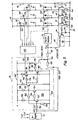
- FIG. 1 shows an arrangement 10 according to the invention, which is used to regulate the speed of a DC motor 12 and to limit the pulse-shaped motor current i mot flowing through this motor to a predetermined maximum value. Furthermore, this arrangement serves to n when a predetermined by a speed regulator 11 rotational speed to switch the motor 12 on braking operation is lowered as far as to its rotational speed, that the desired speed is reached again approximately.
- a freewheeling diode 13 is connected in antiparallel to the motor 12.
- a controllable semiconductor switch 14 is arranged in series with the motor 12 and is controlled by a PWM actuator 15, the latter of which has a special feature with regard to its structure, which is explained in more detail with reference to FIGS. 2 and 3.
- a measuring resistor 18 In series with the semiconductor switch 14 is a measuring resistor 18, at which a measuring voltage u m is generated during operation, which is used to limit the current.
- the motor 12 is connected to a switch 17 in the manner shown Plus line 16 connected, and starting from this plus line goes Current path via the changeover switch 17 to the motor 12, then to the semiconductor switch 14, to the measuring resistor 18, and to a negative lead 20.
- the switch 17 switched to its position 17 ', it makes a short-circuit connection 21st for the engine 12, over which this engine is braked, the height of the Braking current is determined in that the semiconductor switch 14 with a Corresponding duty cycle by the PWM actuator 15 off and on becomes.
- the braking current is also via the measuring resistor 18 measured, and the current limitation prevents a too high Brake current flows. This is particularly important when the engine 12 is one contains permanent magnetic rotor, because the braking current is too high partial or complete demagnetization of the rotor magnet could. (Partial demagnetization means a weakening of the Rotor magnet.)
- the arrangement 10 also contains a monitoring circuit 23 which monitors the voltage between the positive line 16 and the negative line 20 and which also serves to reduce the current in the motor 12 when this voltage U ZWK becomes too high.
- the circuit 23 is of course particularly advantageous if regenerative braking is used, as shown in FIGS. 4 and 5, since the braking process can cause the voltage between the lines 16 and 20 to rise considerably for a short time, which leads to problems could lead if this increase were not limited.
- the speed controller 11 is shown in Fig. 1, to n, a reference speed value supplied, further comprising a speed actual value n, which can for example be provided by a tachometer generator (not shown) which is coupled to the motor 12.
- a speed actual value n can for example be provided by a tachometer generator (not shown) which is coupled to the motor 12.
- this actual speed value is preferably taken from the Hall signals of this motor.
- the speed controller 11 generates a controller output signal REG-OUT at its output, which is fed to a brake controller 24. If this controller output signal is in a range indicated at 86 in Fig. 3a, this indicates that the speed of the motor is too high and consequently the motor 12 must be braked.
- the brake controller 24 then simultaneously effects a switchover of the switch 17 into the position 17 ', the opening of a switch 25, and the closing of a switch 26 via a brake logic contained therein.
- the switch 25, when it is closed, serves to provide the signal To supply REG-OUT to the input 30 of the PWM actuator 15 as a control voltage u ST via a high-resistance resistor 28 (for example 470 k ⁇ ).
- the PWM actuator 15 switches the semiconductor switch 14 on and off in accordance with the level of this signal u ST , the pulse duty factor k corresponding to the level of the voltage u ST . If the REG-OUT signal is high, this means that the motor is too slow, and the pulse duty factor k of the output signals 32 of the PWM actuator 15 consequently becomes high. (The definition of the duty cycle k is given below in Fig. 3.) As the speed increases, the signal REG-OUT becomes lower, and the duty cycle of the signals 32 consequently decreases until it increases at position B in Fig. 3a Becomes zero. In this case, the motor 12 is no longer supplied with current via the semiconductor switch 14.
- the signal u ST has a setting range 85 ', which is shown hatched in FIG. 3a) and which is larger than the predetermined range 84' of FIG. 3a), in which the pulse duty factor k depends u ST changes continuously.
- the pulse duty factor k In the range 95 of the voltage u ST , which lies above the value A in FIG. 3a), the pulse duty factor k always has a value of 100%.
- the signal REG-OUT from the input 30 of the PWM actuator 15 is switched off, and in its place another signal PWM-ACTUATOR is switched to the input 30 of the PWM actuator via the high-resistance resistor 28 via the switch 26 15 fed.
- This signal PWM-STELL determines as a new control signal u ST during the braking process the pulse duty factor k of the output pulses 32 of the PWM actuator 15, that is to say the braking current flowing through the motor 12, and this braking current is determined by the current limitation (transistor 34). limited upwards.
- the braking speed decreases the speed of the motor 12 in the direction of the desired speed, the signal REG-OUT rises again, and when it is in 3a has reached the value D, causes the brake logic in the brake controller 24 renewed switching of the switch 17 into the position shown in FIG. 1, also a switch of the switches 25 and 26, so that the input of the PWM actuator 15 again the controller output signal REG-OUT as a control signal supplied and the substituted control value PWM-STELL is switched off again.
- the voltage u m across the measuring resistor 18 is fed via a resistor 32 to the base of an npn transistor 34, the emitter of which is connected to the negative line 20.
- a capacitor 36 is provided as a prefilter between this base and the negative line 20.
- the collector of transistor 34 is connected via a T-filter 38 (1st order timer) to input 30 of PWM actuator 15 and supplies the signal STBGR to it.
- the T filter 38 contains two resistors 39, 40 connected in series, which are arranged between the collector of the transistor 34 and the input 30 and whose connection point 42 is connected to the negative line 20 via a capacitor 43 (for example 100 nF).
- the transistor 34 becomes conductive has the effect that the control voltage u ST at the input 30 is lowered the more the transistor 34 becomes conductive, and independent of the level of the REG-OUT signal or the PMW-STELL signal, ie the signal STBGR for the current limitation is hierarchically superior to these two other signals.
- transistors are preferably used which are selected with regard to their base-emitter threshold voltage in order to achieve a precisely defined onset of the current limitation.
- the signal at the collector of transistor 50 is referred to as ZK. If the voltage U ZWK between the lines 16 and 20 becomes too high, the transistor 50 becomes conductive and then, like the conductive transistor 34 for which this has already been described, makes a connection from the input of the PWM actuator 15 to the negative line 20 forth, whereby the pulse duty factor of the PWM signals 32 is also reduced in this case in order to take into account the excessively high operating voltage. In this way, as described in more detail below, very simple monitoring and limitation of the intermediate circuit voltage U ZWK is possible in a motor with regenerative braking. - The transistor 50 meets the same criteria as the transistor 34 (selected transistor).
- Fig. 2 explains a preferred structure of the PWM actuator 15, in which the used triangle signal 88 (FIG. 3a) between an amount of 0 different minimum value 91 and a higher amount Maximum value 93 oscillates.
- the PWM actuator 15 contains a triangular oscillator as essential components 60, e.g. vibrates at a frequency of 20 kHz, plus one Comparator 62, and a signal inverter 64, at the output of which pulse-shaped PWM signal 32 occurs, which is also shown in Fig. 3c and that controls the current through the semiconductor switching element 14. (With a duty cycle from 100%, signal 32 becomes a DC voltage signal).
- a triangular oscillator as essential components 60, e.g. vibrates at a frequency of 20 kHz, plus one Comparator 62, and a signal inverter 64, at the output of which pulse-shaped PWM signal 32 occurs, which is also shown in Fig. 3c and that controls the current through the semiconductor switching element 14. (With a duty cycle from 100%, signal 32 becomes a DC voltage signal).
- the triangular oscillator 60 contains a comparator 66, which is useful is designed together with the comparator 62 as a double comparator. Both are in the usual way for power supply to the positive line 16 and the minus line 20 connected. From the output 68 of the comparator 66 leads a positive feedback resistor 70 (e.g. 4.3 k ⁇ ) to its positive input 72, and a negative feedback resistor 74 (e.g. 22 k ⁇ ) also leads from the output 68 to the minus input 76 of the comparator 66. A capacitor 78 (e.g. 1 nF) is located between the minus input 76 and the minus line 20. The output 68 is also connected to the positive line 16 via a resistor 80 (e.g. 2.2 k ⁇ ). The plus input 72 is via two resistors 82, 84 of the same size (e.g. each 10 k ⁇ ) connected to the positive line 16 or the negative line 20.
- a resistor 70 e.g. 4.3 k ⁇
- a triangular oscillator 60 constructed in this way oscillates at a frequency of about 20 kHz, and the triangular voltage 88 it generates is about symmetrical to half the voltage between lines 16 and 20. E.g. at the specified values and an operating voltage of 12 V, the Signal level at the lower peak 91 (FIG. 3a) of the triangular signal 88 about 2 V, is different from 0, and at the top 93 about 9 V.
- the stroke of the triangular signal 88 is designated 84 'in FIG. 3a), as already described, and this stroke 84' is smaller than the possible total stroke 85 'of the signal u ST .
- the triangular signal 88 thus has an offset 86 (FIG. 3a) to the voltage 0 V, that is to the potential of the negative line 20, and this offset is approximately 2 V in the exemplary embodiment, but can of course also be larger or smaller, depending on the dimensioning of the oscillator 60th
- the triangular signal 88 at the minus input 76 is fed to the plus input 90 of the comparator 62. Its negative input corresponds to the input 30 of FIG. 1, and this negative input 30 is supplied with the control signal u ST via the high-resistance resistor 28 (470 k ⁇ ), as already described in FIG. 1.
- This control signal can either be determined by the signal STBGR from the current limiting transistor 34, or by the voltage monitor 23 (FIG. 1), or by the control value PWM-STELL for the braking process, or by the controller output signal REG-OUT.
- the signal STBGR is determined by the magnitude of the current i mot in the motor 12, ie the higher this current, the more - starting from a predetermined threshold value - the transistor 34 becomes conductive and pulls the potential of the minus input 30 down, as a result of which the pulse duty factor k is reduced, and the more the higher the motor current becomes.
- the output 92 of the comparator 62 is connected via a resistor 94 (e.g. 2 k ⁇ ) the positive line 16 connected, further to the input of the inverter 64 the output of which generates the PWM signal 32, which is the semiconductor switching element 14 controls.
- a resistor 94 e.g. 2 k ⁇
- FIG. 2 Referred.
- the potential P1 at the minus input 76 of the comparator 66 e.g. LM 2901
- the potential P2 at its plus input 72 e.g. LM 2901
- the potential P3 at its output 68 e.g. LM 2901
- Resistors 82 and 84 are preferably the same size, e.g. 10 k ⁇ each Resistor 70 has e.g. 4.3 k ⁇ , and the resistor 80 e.g. 2.2 k ⁇ .
- the resistance 74 has e.g. 22 k ⁇ . With an operating voltage of 12 V between the lines 16 and 20, the potential P2 in this case is about 9 V.
- This new potential P2 is about 2 V.
- the charging time of the capacitor 78 results from the series connection of the Resistors 80 and 74. Its discharge time results from resistor 74.
- the potential P2 at the plus input 72 fluctuates at the values described approximately between 9 V and 2 V and is approximately symmetrical to a medium one Voltage of approximately 5.5 V, which is about half the voltage between the lines 16 and 20 corresponds. A small asymmetry of the signal 88 results from resistance 80.
- the potential P1 drops at the positive input of the comparator during operation 62 not below 2 V, so that any potential at the minus input 26 this Comparator that is below 2 V, i.e. outside the predetermined range 84 ', is, a pulse duty factor of the PWM signal 32 of 0% results.
- the current limitation only reduces the Motor current, i.e. the potential at point 30 is then in the specified range 84 'above 2 V corresponding to a pulse duty factor k of greater than 0%, however the pulse duty factor is increased by setting the current limit towards moved to a lower value.
- the offset region 86 also prevents transistors 34 or 50 with greater tolerance deviations a faulty current limitation occurs.
- the circumstance is used to control the braking process exploited that the controller output signal at an excessively high engine speed REG-OUT is in the range of 0 to 2 V. Therefore, when REG-OUT in this voltage range lies, the brake controller 24 and the brake logic are actuated, to initiate braking of the motor 12, as already shown in FIG. 1 has been described.
- the triangular oscillator 60 In operation, the triangular oscillator 60 generates the triangular voltage 88 shown in FIG. 3a.
- the level of the potential at the minus input 30 of the comparator 62 which is designated u 30 in FIG. 3a, 62 square-wave pulses 98 are obtained at the output of the comparator , the shorter the higher the potential u 30 at the minus input 30 becomes.
- the level of this potential thus determines the pulse duty factor of the pulses 92, and these pulses are inverted by the inverter 64, and then the PWM pulses 32 are obtained at the output of the inverter 64, the pulse duty factor k, which is defined below in FIG. 3, also depends on the level of the control signal u ST at the minus input 30. If this signal becomes more positive, the pulse duty factor k and thus the motor current increases, and if this signal becomes more negative, the pulse duty factor and thus the motor current decrease.
- the negative input 30 through the high-resistance 28 the positive controller output signal REG-OUT supplied. This determines then the pulse duty factor of the PWM signal 32.
- the current takes on the motor 12 beyond a certain limit, the transistor 34 conductive, and this creates the signal STBGR at the minus input 30, i.e. the potential at this input shifts in the negative direction because of a Current flows from the input 30 through the transistor 34 to the negative line 20.
- the pulse duty factor k of the PWM pulses 32 decreases, and even more so the motor current becomes higher. This way you get a gentle Current limitation that works practically in an analog way and none additional engine noise or additional EMC interference.
- the current limitation works in the same way when the negative input 30 the signal PWM-STELL is supplied during a braking operation.
- FIG. 4 therefore shows an embodiment of an arrangement according to the invention 110, which uses electronic switches instead, being a motor 112 electronically commutated motor (ECM) is used.
- ECM electronically commutated motor
- the ECM 112 is shown here - as an example - in three lines, with three Stator strings (stator phases) U, V and W, which are connected in star in the example are. A delta connection would also be possible, and another one as well Number of strands.
- the motor works six-pulse, i.e. per rotor rotation of 360 ° el. his stator receives six current pulses.
- the permanent magnetic rotor of the motor 112 is designated 113 and only represented symbolically. Of course, the motor 112 can also be a rotor 113, which is excited by the supply of electricity and not by Permanent magnets.
- the motor 112 also has three Hall generators 115, 116 and 117, the output signals of which are fed to a commutation controller 120, which also derives an actual speed value signal n ist from these Hall signals, which is fed to the speed controller 11 (usually a PI controller) ,
- this commutation controller 120 is designed to deliver commutation signals for the semiconductor switches of the bridge circuit 122 in the usual manner.
- the form of these commutation signals is determined by the output signal of the PWM actuator, ie they are constantly switched on and off by the PWM signal at a high frequency (for example 20 ... 25 kHz), as is shown below with reference to FIG. 11 an example is explained, cf. there the logical combination of the PWM signals 32 with the rotor position signals H1 / and H2 in order to control the bridge transistor 125.
- Hall generators are only shown schematically. It is also an operation possible without Hall generators if the so-called sensorless technology is used.
- the commutation controller 120 is thus designed in the usual way to control the to control six controllable semiconductor switches of the full bridge circuit 122. These semiconductor switches are for better illustration than mechanical ones Switches are shown, but are in reality power transistors, e.g. MOSFETs.
- a first branch of bridge circuit 122 contains two Semiconductor switches 124, 125, at the connection point 126 of the strand U connected.
- a second branch contains two semiconductor switches 128, 129 the connection point 130 of the line V is connected.
- a third branch contains a semiconductor switch 133 above and a semiconductor switch 134 below, at the connection point 135, the strand W is connected. Antiparallel to the individual semiconductor switches each have diodes 124 ', 125', 128 ', 129', 133 'and 134' as shown in FIG. 4.
- the upper semiconductor switches 124, 128 and 133 are connected to a positive line 16.
- a current measuring resistor 138, 139 and 140 which are all connected to a negative line 20.
- U ZWK intermediate circuit voltage
- the voltage limiter 23 already described in FIG limited at the top, e.g. to 48 V.
- the external connections for power supply are 16 'and 20' designated.
- a fuse 142 leads from terminal 16 'to one Sieve capacitor 143 and a protective diode 144, which against high Protects against overvoltages, e.g. against voltages of more than 68 V. Except the fuse 142 is also a strainer 146 in the connection from Connection 16 'to positive line 16 switched on. Left of the throttle 146 is still a filter capacitor 148 is provided.
- the voltage monitor 23 is how shown, arranged in parallel with this filter capacitor 148 and corresponds to in their structure exactly the arrangement 23 of FIG. 1, so that on the local Description can be referenced.
- the voltage across the measuring resistor 138 is also completely analogous to FIG. 1 a resistor 32 is supplied to the base of an npn transistor 34, the one Filter capacitor 36 is assigned. The collector of transistor 34 is over that T-filter 38 connected to the input 30 of the PWM actuator 15.
- the measuring resistors 139 and 140 are assigned completely analog measuring circuits, which are therefore designated with the same reference numerals, but with one apostrophe or two apostrophes.
- the collectors of the four transistors 34, 34 ', 34 "and 50 are connected together; these four transistors are selected transistors with a substantially identical base-emitter threshold voltage U BE so that they all start to conduct at the same voltage and then one Establish a connection from the input 30 to the negative line 20, as a result of which the control voltage u ST at the input 30 is reduced and thus the pulse duty factor k is reduced.
- the controller output signal REG-OUT of the speed controller 11 is the Brake controller 24 fed, and it is a resistor 150 (e.g. 22 k ⁇ ) a node 152 supplied via the high-resistance resistor 28th (e.g. 460 k ⁇ ) is connected to the input 30 of the PWM actuator 15.
- a resistor 150 e.g. 22 k ⁇
- a node 152 supplied via the high-resistance resistor 28th e.g. 460 k ⁇
- the brake controller 24 then generates the signal at its output 154 REG-OUT substituting control signal PWM-STELL when the speed of the Motors 112 has risen so far above the set value that REG-OUT in 3a reaches the low value C. Since REG-OUT over node 152 the relatively high resistance 150 (22 k ⁇ ) is supplied, PWM-STELL on the other hand directly, replaces (substitutes) the PWM-STELL signal with its Occur, that is, when the engine 112 speed is too high, the signal REG-OUT.
- the brake controller 24 When the brake controller 24 receives the PWM-STELL signal at its output 154 generates, it also generates a signal OB at its output 156, which the Commutation control 120 is supplied, which then this the upper Semiconductor switches 124, 128 and 133 of the bridge circuit 122 opens, that is non-conductive, and the lower bridge switches 125, 129 and 134 constantly makes conductive, so turns on, as shown in Fig. 4 as an example.
- the motor 112 then works as a generator, and its generated voltage is supplied via the diodes 124 ', 128' and 133 'of the positive line 16, so that the DC link voltage on this line can rise considerably, such as already described what can lead to damage due to overvoltages.
- this limitation can also be called a performance limitation or Denote "wattage limit", i.e. the braking process is quick but strict within the performance limits of the connected motor 112. (In practice Such a braking process usually lasts only a few seconds, with one Roller shutter motor e.g. approx. 30 seconds.) The desired speed is also after a change in the speed setpoint within a very short time and practical Reached smoothly again.
- the regulator output voltage REG-OUT rises again, and if it has reached the value D in FIG. 3a, the signals PWM-SET and OB switched off again.
- the signal REG-OUT then acts again at input 30, and the commutation controller 120 again operates normally Commutation of the bridge circuit 122 in motor operation. Because such Bridge circuits are known in many variants, this will be normal motor operation not described.
- Fig. 5 shows details of Fig. 4, the same or equivalent parts as in Fig. 4 are denoted by the same reference numerals as there and usually not be described again. Also, not all of the details of FIG. 4 are repeated again, only the essential parts are shown.
- the parts of the brake controller 24 are here with a dash-dotted line border.
- a resistor 150 leads to the base of an npn transistor 152, which together with an npn transistor 154 a flip-flop 156 forms, which has a switching hysteresis and which switches to brakes if that Signal REG-OUT in Fig. 3a reaches the low value C, and the on again motor operation (with speed control) switches back when REG-OUT in 3a again reaches the higher value D.
- a regulated DC voltage of e.g. 12V used between one Plus line 160 and a minus line 165 lies, the latter, as well as the Minus line 20, is connected to ground (GND).
- the base of transistor 152 is connected through a resistor 158 to the negative lead 165 and via a resistor 162 (e.g. 100 k ⁇ ) to the collector of the Transistor 154 connected, the base of which in turn via a resistor 164 (e.g. 22 k ⁇ ) is connected to the collector of transistor 152.
- the collectors of transistors 152, 154 are through resistors 166 and 168, respectively (e.g. 22 k ⁇ ) connected to the positive line 160.
- transistor 154 At the collector of transistor 154 is the base of a transistor 170 connected, whose emitter with the negative line 165 and its collector via a resistor 172 to the positive line 160, via a resistor 174 with the base of an npn transistor 176 and via a resistor 178 with the Base of an NPN transistor 180 is connected.
- the emitter of transistor 176 is connected to the negative line 165, its collector a resistor 182 connected to the positive line 160. On this collector the OB signal is generated during braking, which is transmitted via the Commutation circuit 120, the upper bridge transistors 124, 128 and 133 opens and makes the lower bridge transistors 125, 129 and 134 conductive, unless a priority PWM signal from the lower bridge transistors PWM actuator 15 is present.
- the emitter of transistor 180 is connected to the negative line 165, its collector a resistor 186 with the positive line 160 and a resistor 188 with the base of a pnp transistor 190.
- the emitter of transistor 190 is connected to the positive line 160 via a resistor 192 (e.g. 2.2 k ⁇ ). Its collector, on which, when braking, when transistor 190 is conductive, the PWM-STELL signal is present, is at node 152 between connected to resistors 150 and 28.
- transistor 152 is conductive, and consequently transistor 154 is Tilt level 156 locked.
- the signal REG-OUT becomes very high because the speed increases to high values 3a and falls below the value C of FIG. 3a, the transistor 152 is turned off and transistor 154 is turned on, with the switching by Tilt level 156 occurs suddenly.
- transistor 154 When transistor 154 becomes conductive, previously conductive transistor 170 becomes blocked and in turn makes transistor 176 conductive, so that at its Collector generates the (low) signal OB for the commutation controller 120 becomes.
- blocked transistor 170 makes transistor 180 conductive, and this in turn causes transistor 190 to become conductive so that the latter the signal PWM-STELL generates that as a substitute control value instead of the signal REG-OUT is fed to the PWM actuator 15 during braking and then determines the pulse duty factor k of the PWM actuator 15 during braking, unless the - priority - current limitation and / or the - also priority - voltage limitation.
- This figure thus shows a variant of the circuit of the brake controller 24, which is shown in FIG. 5. While a constant substitute manipulated variable PWM-SET is generated in FIG. 5 when switching to brakes, this substitute manipulated variable in FIG. 6 depends on how large the desired speed n should be : If this speed is only slightly exceeded , only a low substitute control value is generated, ie the pulse duty factor of the PWM signals 32, which determine the level of the braking current during the braking process, is relatively small in this case. However, if this speed is greatly exceeded, a higher substitute control value is generated and the braking current consequently becomes correspondingly higher. This has the advantage that the switching on and off of the brake is smooth, that is, the transition to braking, and the transition from braking to motor operation, occurs smoothly and without noticeable discontinuities.
- two operational amplifiers 200, 201 are used.
- the controller output signal REG-OUT from the speed controller 11 is in the the negative input of both operational amplifiers 200, 201 fed.
- the negative input of operational amplifier 200 is via a Resistor 207 connected to its output, so that this Operational amplifier works as an amplifier with adjustable gain, and this output is connected via a diode 202 to a connection which is like is designated by 154 in FIG. 4.
- the operational amplifier 201 is connected as a comparator and generates on its output 156 the OB signal when REG-OUT becomes lower than that Potential B.
- This signal OB causes the upper semiconductor switches 124, 128 and 133 of the bridge circuit 122 are opened, that the lower Semiconductor switches 125, 129 and 134 are closed, and that these lower Semiconductor switches are subject to control by the PWM signal 32. This will be explained in more detail below.
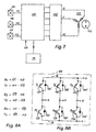
- Fig. 7 shows again - in the form of a block diagram - the basic Structure of the electronics for the ECM 112. This is used in this example three Hall generators 115, 116 and 117, which from the rotor magnet 113 are controlled and produce Hall signals H1, H2 and H3, which of Commutation control 120 are supplied, which in turn the Bridge circuit 122 controls.
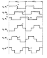
- Fig. 9a shows the Hall signal H1, Fig. 9b that Hall signal H2, and Fig. 9c the Hall signal H3.
- the PWM actuator 15 (Fig. 2) acts on the commutation controller 120 (see FIG. 11 below), as well Signal OB from the brake logic, which is shown in Fig. 4, 5 and 6.
- FIG. 8B shows the basic structure of the bridge circuit 122 with three upper ones PNP bridge transistors 124, 128 and 133 as well as three lower NPN bridge transistors 125, 129 and 134.
- Figure 8A shows the associated ones Control signals from Hall generators 115, 116 and 117. becomes the top Bridge transistor 124 controlled by the signal T1, which comes from the logic Link (conjunction) of the Hall signal H1 and the negated Hall signal H2 / formed becomes.
- FIG. 9 shows the Hall signals H1, H2 and H3 and the commutation of the strands U (Fig. 9d), V (Fig. 9e) and W (Fig. 9f) of the ECM 112 in the event that none Speed control, braking and also no current limitation takes place.
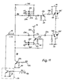
- FIG. 10 shows the evaluation of the Hall signals H1, H2 and H3 and the - in each case by a transistor 210, 210 'or 210 "inverted - Hall signals H1 /, H2 / or. H3 / to control the bridge transistors, namely, from didactic Reasons, initially without PWM control (the latter is shown in Fig. 11)
- the signals H1 and H2 / which are two as an AND gate Serving diodes 212, 213 to the base of a phase reversing transistor 216 (NPN) are led, the collector via a resistor 218 with the base of the Bridge transistor 124 is connected. If signal H1 or signal H2 / low, thus the transistor 216 is blocked, and through it also the Bridge transistor 124. If both signals H1 and H2 / high, then the conducts Bridge transistor 124.
- the lower bridge transistor 125 is also connected as an AND gate acting logic diodes 220, 221 controlled by the signals H1 / and H2. If both signals are high, the bridge transistor 125 becomes conductive. Otherwise it is he locked.
- Bridge transistor 128 is controlled by its in a completely analog manner Control transistor 216 ', and the bridge transistor 133 via its control transistor 216 ". For the specialist, everything essential results from the circuit.
- the signal OB is inverted by an npn transistor 224, at the Output one receives the OB / signal, which is low when OB is high.
- the signal OB / is supplied to a node S1 via a diode 226 which are also connected to diodes 212 and 213. So you get at S1 the logical link H1 & H2 / & OB /, i.e. if OB / is low, the top one Bridge transistor 124 blocked, and the top in a completely analogous manner Bridge transistors 128 and 133.
- the OB / signal is also fed to the base of an NPN transistor 230 and turns it off when it is low, causing the base of bridge transistor 125 a starting current from the positive line 16 constantly via a resistor 232 receives, i.e. when braking, the lower bridge transistors become permanent switched on and the commutation is switched off.
- the collector of transistor 230 is one Junction S2 and connected to positive line 16 via resistor 232.
- a diode 234 leads from the node S2 to the base of the bridge transistor 125.
- the node S2 is connected to the output of the via a diode 236 Inverter 64 (see FIG. 2) connected and receives the PWM signal 32 from there. Every time this signal 32 goes low, node S2 gets one low potential and blocks the lower bridge transistor 125. Is against If the PWM signal 32 is high, then the bridge transistor 125 remains conductive when it by the other signals (the OB / signal, or the combination of the signals H1 / and H2) is controlled to be conductive. The same applies to the other two below Bridge transistors 129 and 134.
- the PWM signal 32 therefore has priority here, ie if it goes low, it blocks the bridge transistor 125 in any case, and in an analogous manner the bridge transistors 129 and 134, so that the current in the motor is interrupted when the PWM signal 32 becomes low. As already described, this enables a current limitation during braking and a limitation of the voltage U ZWK .
- the lower bridge transistors 125, 129 and 134 are blocked by the PWM signal 32 if the motor current becomes too high.
- the lower bridge transistors are not commutated, but continuously controlled by the signal OB (from the brake logic), but even when braking, these bridge transistors are then interrupted (by the PWM signal) when the braking current and / or the intermediate circuit voltage U ZWK get too high.
Landscapes
- Engineering & Computer Science (AREA)
- Power Engineering (AREA)
- Control Of Motors That Do Not Use Commutators (AREA)
- Control Of Direct Current Motors (AREA)
- Exhaust-Gas Circulating Devices (AREA)
- Stopping Of Electric Motors (AREA)
Claims (14)
- Procédé pour commander ou régler un moteur électrique, auquel on peut amener du courant au moyen au moins d'un interrupteur à semi-conducteurs, lequel interrupteur est amorcé pendant le fonctionnement par un actionneur à modulation d'impulsions en largeur avec un signal pulsé comportant les étapes suivantes :à l'entrée de l'actionneur à modulation d'impulsions en largeur, on amène pour la commande du taux d'impulsions (k) du signal pulsé par l'intermédiaire d'une première résistance un premier signal analogique (figure 1 : PWM-STELL ; REG-OUT) sous la forme d'un premier potentiel, qui a une fonction au moins du régime moteur ;lors de l'apparition d'un deuxième signal prioritaire, qui a une fonction au moins du courant moteur, l'entrée de l'actionneur à modulation d'impulsions en largeur est reliée par un dispositif de résistance commandé par ce deuxième signal, qui est à faible valeur ohmique par rapport à la première résistance, est reliée à un deuxième potentiel différent du premier potentiel, afin de réduire en fonction de la grandeur de ce deuxième signal le taux d'impulsions avec lequel le/au moins un interrupteur à semi-conducteurs est amorcé,
de sorte que le potentiel à l'entrée de l'actionneur à modulation d'impulsions en largeur et donc le taux d'impulsions (k) de l'actionneur à modulation d'impulsions en largeur sont déterminés au moins principalement par la grandeur du premier signal, aussi longtemps que le courant moteur ne dépasse pas une valeur prédéfinie,
et est déterminé au moins principalement par la grandeur du deuxième signal analogique lors d'un dépassement de cette valeur prédéfinie. - Procédé selon la revendication 1, dans lequel le premier signal analogique est un signal dépendant du régime ou commandant le régime (PWM-STELL).
- Procédé selon la revendication 1, dans lequel le deuxième signal analogique est commandé par au moins un organe de mesure commandé par le courant moteur (imot) et est filtré avant son arrivée à l'actionneur à modulation d'impulsions en largeur.
- Procédé selon la revendication 3, dans lequel le moteur électrique est un moteur à commutation électronique avec plusieurs branches,
le courant circulant dans le moteur est enregistré séparément pour chaque branche,
et le deuxième signal analogique est déterminé par le courant de branche qui est maximum à l'instant donné. - Procédé selon la revendication 1, dans lequel le deuxième signal analogique est commandé en supplément par la tension continue (UZWK) entre deux lignes (16, 20) auxquelles le moteur (122) est raccordé
et auxquelles le moteur restitue lors d'une opération de freinage de l'énergie qui augmente la tension entre ces lignes. - Procédé selon la revendication 1, dans lequel l'actionneur à modulation d'impulsions en largeur présente une plage de réglage (figure 3a : 86), dans laquelle un signal d'entrée (UST), dont la valeur est différente de 0, entraíne un taux d'impulsions (k) du signal pulsé de 0%.
- Procédé selon la revendication 1, dans lequel, dans les cas où le premier signal analogique est situé dans une plage de signal prédéfinie (figure 3a : inférieure à C), il est substitué par un autre signal analogique (PWM-STELL) pour l'actionneur à modulation d'impulsions en largeur (15).
- Procédé selon la revendication 7, dans lequel la grandeur du signal substitué (PWM-STELL) est déterminée par la grandeur du signal de sortie (REG-OUT) d'un régulateur de régime attribué au moteur.
- Procédé selon la revendication 7, dans lequel la grandeur du signal substitué (PWM-STELL) est déterminée par la grandeur d'un courant de freinage circulant dans le moteur.
- Dispositif pour un moteur (12; 112) alimenté en courant au moyen au moins d'un interrupteur à semi-conducteurs (14; 124, 125, 128, 129, 133, 134),
avec un actionneur à modulation d'amplitude en largeur (15) qui peut être commandé par un signal de réglage (UST), qui modifie son taux d'impulsions (k) dans le cas d'une variation de ce signal de réglage dans les limites d'une plage prédéfinie de signal de réglage (figure 3a : 84'), mais pas en-dehors de cette plage de signal de réglage,
et qui sert à déconnecter et connecter de façon répétitive, en fonction du niveau du signal de réglage (UST), le/au moins un interrupteur à semi-conducteurs avec un taux d'impulsions (k) attribué à la grandeur du signal de réglage,
équipé également d'un dispositif de réglage (11) pour le réglage du régime moteur, dont le signal de sortie de régulateur (REG-OUT) est amené à une entrée (30) de l'actionneur à modulation d'impulsions en largeur (15) au moyen d'une résistance (28; 150) comme signal de réglage et présente une plage de signal (figure 3a : 85'), qui est supérieure à la plage prédéfinie de signal de réglage (figure 3a : 84'),
et d'une résistance de mesure (18; 138, 139, 140) pour l'enregistrement d'un courant moteur (imot),
moyennant quoi la tension (Um) sur cette résistance de mesure est amenée à l'entrée d'un transistor (34, 34', 34") réagissant à une tension seuil prédéfinie ou à un comparateur, lequel modifie le signal à l'entrée (30) de l'actionneur à modulation d'impulsions en largeur (15) lors de son activation de façon prioritaire avant le signal de sortie du régulateur (REG-OUT) de telle façon que ce courant moteur (imot) est réduit. - Dispositif selon la revendication 10, dans lequel le courant moteur (imot) enregistré sur la résistance de mesure présente la forme d'impulsions de courant,
et au moins un filtre (38) est prévu entre la résistance de mesure (18; 138, 139, 140) et l'entrée (30) de l'actionneur à modulation d'impulsions en largeur (15). - Dispositif selon la revendication 11, dans lequel le filtre est conçu comme un filtre en T (38).
- Dispositif selon l'une quelconque des revendications 10 à 12 pour un moteur (112) à commutation électrique avec plusieurs phases (U, V, W), qui sont alimentées en courant pendant le service au moyen d'un circuit en pont (122), des circuits séparés de mesure de courant étant prévus pour des branches de pont individuelles et les signaux de sortie de ces circuits de mesure de courant pouvant être amenés conjointement à l'actionneur à modulation d'impulsions en largeur (15), afin de modifier le signal à l'entrée (30) de l'actionneur à modulation d'impulsions en largeur (15) en cas de dépassement d'une valeur de courant prédéfinie dans une branche de pont de façon prioritaire avant le signal de sortie de régulateur (REG-OUT), de telle façon que ce courant est réduit.
- Dispositif selon la revendication 13, dans lequel des agencements de filtre (38; 36, 36', 36") sont attribués aussi bien aux circuits individuels de mesure de courant qu'à leur signal de sortie commun.
Applications Claiming Priority (4)
| Application Number | Priority Date | Filing Date | Title |
|---|---|---|---|
| DE29506842U | 1995-04-22 | ||
| DE29506843U | 1995-04-22 | ||
| DE29506842 | 1995-04-22 | ||
| DE29506843 | 1995-04-22 |
Publications (3)
| Publication Number | Publication Date |
|---|---|
| EP0739084A2 EP0739084A2 (fr) | 1996-10-23 |
| EP0739084A3 EP0739084A3 (fr) | 1998-03-04 |
| EP0739084B1 true EP0739084B1 (fr) | 2002-07-24 |
Family
ID=26057832
Family Applications (1)
| Application Number | Title | Priority Date | Filing Date |
|---|---|---|---|
| EP96105919A Expired - Lifetime EP0739084B1 (fr) | 1995-04-22 | 1996-04-16 | Procédé de commande ou réglage d'un moteur électrique et dispositif pour mettre en oeuvre ce procédé |
Country Status (3)
| Country | Link |
|---|---|
| US (1) | US5933573A (fr) |
| EP (1) | EP0739084B1 (fr) |
| DE (2) | DE59609466D1 (fr) |
Families Citing this family (43)
| Publication number | Priority date | Publication date | Assignee | Title |
|---|---|---|---|---|
| DE19949804A1 (de) * | 1998-11-09 | 2000-05-11 | Papst Motoren Gmbh & Co Kg | Elektronisch kommutierter Motor |
| WO2001059921A1 (fr) | 2000-02-07 | 2001-08-16 | Papst-Motoren Gmbh & Co. Kg | Dispositif pour l'alimentation, a partir d'un reseau a courant continu, d'un consommateur dont la consommation se fait par intermittences, en particulier d'un moteur a courant continu |
| DE10022924A1 (de) * | 2000-05-11 | 2001-11-15 | Bayerische Motoren Werke Ag | Schaltungsanordnung zum Betrieb eines Motors |
| DE20105050U1 (de) | 2000-05-27 | 2001-06-28 | Papst-Motoren GmbH & Co. KG, 78112 St Georgen | Motoranordnung |
| EP1314242B1 (fr) * | 2000-08-30 | 2008-09-17 | ebm-papst St. Georgen GmbH & Co. KG | Procede de commande et de reglage du courant dans une machine a courant continu et machine a courant continu pour ce procede |
| US6997684B2 (en) * | 2000-08-30 | 2006-02-14 | Ebm-Papst St. Georgen Gmbh & Co. Kg | Fan motor with digital controller for applying substantially constant driving current |
| WO2002019510A1 (fr) * | 2000-08-30 | 2002-03-07 | Papst-Motoren Gmbh & Co. Kg | Generatrice a courant continu avec dispositif de limitation de courant regulable |
| DE10247900A1 (de) * | 2002-10-14 | 2004-04-22 | Robert Bosch Gmbh | Verfahren und Vorrichtung zur Stromversorgung eines elektronisch kommutierbaren Elektromotors |
| US7038410B2 (en) * | 2002-12-23 | 2006-05-02 | Delphi Technologies, Inc. | Electric motor with dynamic damping |
| SE526270C2 (sv) * | 2003-03-19 | 2005-08-09 | Forskarpatent I Syd Ab | Seriemagnetisering av synkronmotorer |
| US20060272444A1 (en) * | 2005-06-03 | 2006-12-07 | Ray Cockerham | Electromechanical cable actuator assembly controller |
| FI118406B (fi) * | 2006-09-11 | 2007-10-31 | Kone Corp | Menetelmä ja laitteisto moottorin jarruttamiseksi |
| ATE523952T1 (de) * | 2007-12-18 | 2011-09-15 | Ebm Papst St Georgen Gmbh & Co | Elektronisch kommutierter motor |
| US8198843B2 (en) | 2008-06-17 | 2012-06-12 | Asmo Co., Ltd. | Motor control apparatus and motor control method |
| US20120044292A1 (en) * | 2010-08-17 | 2012-02-23 | Markem-Imaje Corporation | Vacuum Control For Print Head of A Printing System |
| US8947242B2 (en) | 2011-12-15 | 2015-02-03 | Honeywell International Inc. | Gas valve with valve leakage test |
| US8839815B2 (en) | 2011-12-15 | 2014-09-23 | Honeywell International Inc. | Gas valve with electronic cycle counter |
| US9851103B2 (en) | 2011-12-15 | 2017-12-26 | Honeywell International Inc. | Gas valve with overpressure diagnostics |
| US9835265B2 (en) | 2011-12-15 | 2017-12-05 | Honeywell International Inc. | Valve with actuator diagnostics |
| US9995486B2 (en) | 2011-12-15 | 2018-06-12 | Honeywell International Inc. | Gas valve with high/low gas pressure detection |
| US8905063B2 (en) | 2011-12-15 | 2014-12-09 | Honeywell International Inc. | Gas valve with fuel rate monitor |
| US9074770B2 (en) | 2011-12-15 | 2015-07-07 | Honeywell International Inc. | Gas valve with electronic valve proving system |
| US9846440B2 (en) | 2011-12-15 | 2017-12-19 | Honeywell International Inc. | Valve controller configured to estimate fuel comsumption |
| US8899264B2 (en) | 2011-12-15 | 2014-12-02 | Honeywell International Inc. | Gas valve with electronic proof of closure system |
| US9557059B2 (en) | 2011-12-15 | 2017-01-31 | Honeywell International Inc | Gas valve with communication link |
| US9234661B2 (en) | 2012-09-15 | 2016-01-12 | Honeywell International Inc. | Burner control system |
| US10422531B2 (en) | 2012-09-15 | 2019-09-24 | Honeywell International Inc. | System and approach for controlling a combustion chamber |
| EP2868970B1 (fr) | 2013-10-29 | 2020-04-22 | Honeywell Technologies Sarl | Dispositif de régulation |
| US9632111B2 (en) * | 2013-12-10 | 2017-04-25 | Infineon Technologies Ag | Passive input filter with clamping for shunt measurements |
| US10024439B2 (en) | 2013-12-16 | 2018-07-17 | Honeywell International Inc. | Valve over-travel mechanism |
| KR20240036141A (ko) * | 2014-06-17 | 2024-03-19 | 카티바, 인크. | 인쇄 시스템 조립체 및 방법 |
| US12251946B2 (en) | 2014-06-17 | 2025-03-18 | Kateeva, Inc. | Printing system assemblies and methods |
| US9841122B2 (en) | 2014-09-09 | 2017-12-12 | Honeywell International Inc. | Gas valve with electronic valve proving system |
| US9645584B2 (en) | 2014-09-17 | 2017-05-09 | Honeywell International Inc. | Gas valve with electronic health monitoring |
| US10503181B2 (en) | 2016-01-13 | 2019-12-10 | Honeywell International Inc. | Pressure regulator |
| US9961783B2 (en) | 2016-07-08 | 2018-05-01 | Kateeva, Inc. | Guided transport path correction |
| US10564062B2 (en) | 2016-10-19 | 2020-02-18 | Honeywell International Inc. | Human-machine interface for gas valve |
| US11073281B2 (en) | 2017-12-29 | 2021-07-27 | Honeywell International Inc. | Closed-loop programming and control of a combustion appliance |
| US10697815B2 (en) | 2018-06-09 | 2020-06-30 | Honeywell International Inc. | System and methods for mitigating condensation in a sensor module |
| CN109209977B (zh) * | 2018-11-28 | 2023-08-22 | 郑州云海信息技术有限公司 | 一种对风扇调速的pwm控制装置及其应用方法 |
| US12231066B2 (en) | 2021-07-16 | 2025-02-18 | Carrier Corporation | Two degrees of control through pulse width modulation interface |
| WO2024260545A1 (fr) * | 2023-06-20 | 2024-12-26 | Johnson Electric Germany GmbH & Co. KG | Procédé de commande de l'unité d'entraînement d'un dispositif d'ombrage |
| TWI872619B (zh) * | 2023-07-25 | 2025-02-11 | 陞達科技股份有限公司 | 馬達控制偵測器及馬達控制方法 |
Family Cites Families (22)
| Publication number | Priority date | Publication date | Assignee | Title |
|---|---|---|---|---|
| DE2622656C2 (de) * | 1976-05-20 | 1982-09-09 | Kaltenbach & Voigt Gmbh & Co, 7950 Biberach | Schaltungsanordnung zum Regeln der Drehzahl eines Gleichstrommotors, insbesondere für zahnärztliche Handgeräte |
| US4368411A (en) * | 1981-07-13 | 1983-01-11 | Kollmorgen Technologies Corporation | Control system for electric motor |
| DE3221093A1 (de) * | 1982-06-04 | 1983-12-08 | Brown, Boveri & Cie Ag, 6800 Mannheim | Anordnung fuer eine getaktete spannungsverstellung |
| DE3231388A1 (de) * | 1982-08-24 | 1984-03-01 | Teldix Gmbh, 6900 Heidelberg | Kollektorloser gleichstrommotor |
| JPS60261387A (ja) * | 1984-06-07 | 1985-12-24 | Sony Corp | モ−タのドライブ回路 |
| JPS6188774A (ja) * | 1984-10-05 | 1986-05-07 | Mitsubishi Electric Corp | エレベ−タの制御装置 |
| US4843297A (en) * | 1984-11-13 | 1989-06-27 | Zycron Systems, Inc. | Microprocessor speed controller |
| US4622500A (en) * | 1985-07-11 | 1986-11-11 | The Machlett Laboratories, Inc. | Electric motor controller |
| DE3537403C2 (de) * | 1985-10-21 | 1995-06-01 | Papst Motoren Gmbh & Co Kg | Kollektorloser Gleichstrommotor mit oder für einen Lüfter |
| DE3603294A1 (de) * | 1986-02-04 | 1987-08-06 | Artur Zimmermann | Verfahren und vorrichtung zur erfassung der einer oder mehreren energieabgabeeinrichtungen zugefuehrten energiemenge |
| US4803410A (en) * | 1986-02-07 | 1989-02-07 | Hitachi Koki Company, Ltd. | Variable duty ratio speed controller for DC motors |
| JP3041872B2 (ja) * | 1990-02-28 | 2000-05-15 | スズキ株式会社 | 電動車の速度制御装置 |
| US5039924A (en) * | 1990-05-07 | 1991-08-13 | Raymond Corporation | Traction motor optimizing system for forklift vehicles |
| KR100201267B1 (ko) * | 1990-05-16 | 1999-06-15 | 가와모토 노부히코 | 전동차량의 회생제동장치 |
| MY107328A (en) * | 1990-07-06 | 1995-11-30 | Hitachi Ltd | Brushless motor incorporating an integrated circuit having a one-chipped peripheral circuit. |
| NZ280025A (en) * | 1990-12-19 | 1997-12-19 | Fisher & Paykel | Speed control of multiphase electronically controlled motor |
| DE4042041A1 (de) * | 1990-12-28 | 1992-07-02 | Jungheinrich Ag | Fahrantrieb fuer flurfoerderfahrzeuge |
| JP3128845B2 (ja) * | 1991-02-27 | 2001-01-29 | スズキ株式会社 | 電動車両の速度制御装置 |
| DE4228973A1 (de) * | 1992-08-31 | 1994-03-10 | Grundfos A S Bjerringbro | Verfahren und Einrichtung zur Messung elektrischer Größen, insbesondere des Stroms, an einem frequenzumformergesteuerten Elektromotor |
| DE4327483A1 (de) * | 1993-08-16 | 1995-02-23 | Bosch Gmbh Robert | Verfahren und Vorrichtung zur Ansteuerung eines Leistungsstellelements einer Antriebseinheit eines Fahrzeugs |
| US5578911A (en) * | 1994-09-21 | 1996-11-26 | Chrysler Corporation | Method and apparatus for power regeneration in an electric vehicle motor drive using a deadtime generator and having continuously variable regeneration control |
| DE29500014U1 (de) * | 1995-01-02 | 1995-03-02 | Industrial Technology Research Institute, Chutung, Hsinchu | Drehzahlregler für einen bürstenlosen Gleichstrom-Motor |
-
1996
- 1996-04-16 DE DE59609466T patent/DE59609466D1/de not_active Expired - Lifetime
- 1996-04-16 EP EP96105919A patent/EP0739084B1/fr not_active Expired - Lifetime
- 1996-04-17 DE DE19615072A patent/DE19615072A1/de not_active Withdrawn
- 1996-04-17 US US08/633,909 patent/US5933573A/en not_active Expired - Lifetime
Also Published As
| Publication number | Publication date |
|---|---|
| EP0739084A3 (fr) | 1998-03-04 |
| EP0739084A2 (fr) | 1996-10-23 |
| DE19615072A1 (de) | 1996-10-24 |
| US5933573A (en) | 1999-08-03 |
| DE59609466D1 (de) | 2002-08-29 |
Similar Documents
| Publication | Publication Date | Title |
|---|---|---|
| EP0739084B1 (fr) | Procédé de commande ou réglage d'un moteur électrique et dispositif pour mettre en oeuvre ce procédé | |
| EP1413044B1 (fr) | Procede pour faire fonctionner un moteur a commutation electronique et moteur pour la mise en oeuvre dudit procede | |
| EP0425479B1 (fr) | Commande de moteur à courant continu sans collecteur, plus spécialement pour actionner un ventilateur | |
| DE69726485T2 (de) | Stromformung in Reluktanzmachinen | |
| EP1415390B1 (fr) | Procede pour commander la commutation dans un moteur a commutation electronique et moteur a commutation electronique permettant la mise en oeuvre de ce procede | |
| EP0865681A1 (fr) | Procede de regulation d'une grandeur physique, et dispositif pour la mise en oeuvre dudit procede | |
| DE3934139A1 (de) | Elektronische steuerschaltung fuer einen buerstenlosen gleichstrommotor | |
| DE60009780T2 (de) | Motor-Startschaltung, insbesondere für Kühlschrankkompressoren | |
| DE19704089C2 (de) | Verfahren zur Steuerung eines Zerhacker(Chopper)-Treibers und Schaltungsanordnung zur Durchführung des Verfahrens | |
| DE29902571U1 (de) | Elektronisch kommutierter Motor | |
| DE2306607A1 (de) | Schaltungsanordnung zur ansteuerung einer induktiven last | |
| DE69200655T2 (de) | Schaltung zur Regelung der Ladespannung einer mittels eines Generators gespeisten Batterie. | |
| EP0467085B1 (fr) | Circuit d'attaque pour moteur à courant continu sans balai | |
| DE68923785T2 (de) | Gleichstrommotor. | |
| DE3044027A1 (de) | Drehzahlregelanordnung | |
| DE2731501C3 (de) | Regelanordnung für einen mit Reihenschluß-Nebenschluß-Umschaltung betriebenen Gleichstrommotor | |
| WO1997048177A1 (fr) | Systeme comportant un moteur a commutation electronique | |
| DE4311533B4 (de) | Ansteuerschaltung für einen kollektorlosen Gleichstrommotor | |
| DE19519248A1 (de) | Verfahren zur Strombegrenzung bei einem Gleichstrommotor, und Gleichstrommotor zur Durchführung eines solchen Verfahrens | |
| DE69800956T2 (de) | Zeitpunktregler | |
| DE29606952U1 (de) | Anordnung mit einem über mindestens einen Halbleiterschalter mit Strom versorgten Verbraucher | |
| DE29606939U1 (de) | Anordnung mit einem PWM-Steller | |
| DE102005016333B4 (de) | Verfahren und Steuersystem zur Kommutierung eines einsträngigen bürstenlosen Motors | |
| EP1472783B1 (fr) | Procede permettant de commuter un moteur electroniquement commute et moteur permettant la mise en oeuvre de ce procede | |
| WO2000074205A2 (fr) | Procede et circuits permettant de reguler la puissance d'une machine a reluctance a deux phases, commutee electroniquement |
Legal Events
| Date | Code | Title | Description |
|---|---|---|---|
| PUAI | Public reference made under article 153(3) epc to a published international application that has entered the european phase |
Free format text: ORIGINAL CODE: 0009012 |
|
| AK | Designated contracting states |
Kind code of ref document: A2 Designated state(s): CH DE FR GB IT LI NL SE |
|
| PUAL | Search report despatched |
Free format text: ORIGINAL CODE: 0009013 |
|
| AK | Designated contracting states |
Kind code of ref document: A3 Designated state(s): CH DE FR GB IT LI NL SE |
|
| RHK1 | Main classification (correction) |
Ipc: H02P 5/17 |
|
| 17P | Request for examination filed |
Effective date: 19980305 |
|
| 17Q | First examination report despatched |
Effective date: 19991018 |
|
| GRAG | Despatch of communication of intention to grant |
Free format text: ORIGINAL CODE: EPIDOS AGRA |
|
| GRAG | Despatch of communication of intention to grant |
Free format text: ORIGINAL CODE: EPIDOS AGRA |
|
| GRAH | Despatch of communication of intention to grant a patent |
Free format text: ORIGINAL CODE: EPIDOS IGRA |
|
| GRAH | Despatch of communication of intention to grant a patent |
Free format text: ORIGINAL CODE: EPIDOS IGRA |
|
| GRAA | (expected) grant |
Free format text: ORIGINAL CODE: 0009210 |
|
| AK | Designated contracting states |
Kind code of ref document: B1 Designated state(s): CH DE FR GB IT LI NL SE |
|
| PG25 | Lapsed in a contracting state [announced via postgrant information from national office to epo] |
Ref country code: NL Free format text: LAPSE BECAUSE OF FAILURE TO SUBMIT A TRANSLATION OF THE DESCRIPTION OR TO PAY THE FEE WITHIN THE PRESCRIBED TIME-LIMIT Effective date: 20020724 Ref country code: IT Free format text: LAPSE BECAUSE OF FAILURE TO SUBMIT A TRANSLATION OF THE DESCRIPTION OR TO PAY THE FEE WITHIN THE PRESCRIBED TIME-LIMIT;WARNING: LAPSES OF ITALIAN PATENTS WITH EFFECTIVE DATE BEFORE 2007 MAY HAVE OCCURRED AT ANY TIME BEFORE 2007. THE CORRECT EFFECTIVE DATE MAY BE DIFFERENT FROM THE ONE RECORDED. Effective date: 20020724 |
|
| REG | Reference to a national code |
Ref country code: GB Ref legal event code: FG4D Free format text: NOT ENGLISH |
|
| REG | Reference to a national code |
Ref country code: CH Ref legal event code: EP |
|
| REF | Corresponds to: |
Ref document number: 59609466 Country of ref document: DE Date of ref document: 20020829 |
|
| GBT | Gb: translation of ep patent filed (gb section 77(6)(a)/1977) |
Effective date: 20020813 |
|
| PG25 | Lapsed in a contracting state [announced via postgrant information from national office to epo] |
Ref country code: SE Free format text: LAPSE BECAUSE OF FAILURE TO SUBMIT A TRANSLATION OF THE DESCRIPTION OR TO PAY THE FEE WITHIN THE PRESCRIBED TIME-LIMIT Effective date: 20021024 |
|
| NLV1 | Nl: lapsed or annulled due to failure to fulfill the requirements of art. 29p and 29m of the patents act | ||
| ET | Fr: translation filed | ||
| PG25 | Lapsed in a contracting state [announced via postgrant information from national office to epo] |
Ref country code: LI Free format text: LAPSE BECAUSE OF NON-PAYMENT OF DUE FEES Effective date: 20030430 Ref country code: CH Free format text: LAPSE BECAUSE OF NON-PAYMENT OF DUE FEES Effective date: 20030430 |
|
| PLBE | No opposition filed within time limit |
Free format text: ORIGINAL CODE: 0009261 |
|
| STAA | Information on the status of an ep patent application or granted ep patent |
Free format text: STATUS: NO OPPOSITION FILED WITHIN TIME LIMIT |
|
| 26N | No opposition filed |
Effective date: 20030425 |
|
| REG | Reference to a national code |
Ref country code: CH Ref legal event code: PL |
|
| REG | Reference to a national code |
Ref country code: FR Ref legal event code: CD |
|
| PGFP | Annual fee paid to national office [announced via postgrant information from national office to epo] |
Ref country code: FR Payment date: 20140225 Year of fee payment: 19 |
|
| PGFP | Annual fee paid to national office [announced via postgrant information from national office to epo] |
Ref country code: GB Payment date: 20140210 Year of fee payment: 19 |
|
| REG | Reference to a national code |
Ref country code: DE Ref legal event code: R084 Ref document number: 59609466 Country of ref document: DE |
|
| REG | Reference to a national code |
Ref country code: DE Ref legal event code: R082 Ref document number: 59609466 Country of ref document: DE |
|
| REG | Reference to a national code |
Ref country code: DE Ref legal event code: R079 Ref document number: 59609466 Country of ref document: DE Free format text: PREVIOUS MAIN CLASS: H02P0005170000 Ipc: H02P0007290000 |
|
| REG | Reference to a national code |
Ref country code: DE Ref legal event code: R084 Ref document number: 59609466 Country of ref document: DE Effective date: 20141119 Ref country code: DE Ref legal event code: R079 Ref document number: 59609466 Country of ref document: DE Free format text: PREVIOUS MAIN CLASS: H02P0005170000 Ipc: H02P0007290000 Effective date: 20141205 |
|
| PGFP | Annual fee paid to national office [announced via postgrant information from national office to epo] |
Ref country code: DE Payment date: 20150401 Year of fee payment: 20 |
|
| GBPC | Gb: european patent ceased through non-payment of renewal fee |
Effective date: 20150416 |
|
| PG25 | Lapsed in a contracting state [announced via postgrant information from national office to epo] |
Ref country code: GB Free format text: LAPSE BECAUSE OF NON-PAYMENT OF DUE FEES Effective date: 20150416 |
|
| REG | Reference to a national code |
Ref country code: FR Ref legal event code: ST Effective date: 20151231 |
|
| PG25 | Lapsed in a contracting state [announced via postgrant information from national office to epo] |
Ref country code: FR Free format text: LAPSE BECAUSE OF NON-PAYMENT OF DUE FEES Effective date: 20150430 |
|
| REG | Reference to a national code |
Ref country code: DE Ref legal event code: R071 Ref document number: 59609466 Country of ref document: DE |