EP0467085B1 - Circuit d'attaque pour moteur à courant continu sans balai - Google Patents
Circuit d'attaque pour moteur à courant continu sans balai Download PDFInfo
- Publication number
- EP0467085B1 EP0467085B1 EP91110041A EP91110041A EP0467085B1 EP 0467085 B1 EP0467085 B1 EP 0467085B1 EP 91110041 A EP91110041 A EP 91110041A EP 91110041 A EP91110041 A EP 91110041A EP 0467085 B1 EP0467085 B1 EP 0467085B1
- Authority
- EP
- European Patent Office
- Prior art keywords
- circuit
- output
- stage
- driving circuit
- control circuit
- Prior art date
- Legal status (The legal status is an assumption and is not a legal conclusion. Google has not performed a legal analysis and makes no representation as to the accuracy of the status listed.)
- Expired - Lifetime
Links
- 239000003990 capacitor Substances 0.000 claims description 16
- 238000004804 winding Methods 0.000 claims description 10
- 230000001105 regulatory effect Effects 0.000 claims description 6
- 238000012544 monitoring process Methods 0.000 claims description 5
- 230000001276 controlling effect Effects 0.000 claims description 3
- 238000007599 discharging Methods 0.000 claims 1
- 238000001816 cooling Methods 0.000 description 3
- 230000000694 effects Effects 0.000 description 3
- 230000033228 biological regulation Effects 0.000 description 2
- 238000010586 diagram Methods 0.000 description 2
- 230000006978 adaptation Effects 0.000 description 1
- 230000000903 blocking effect Effects 0.000 description 1
- 230000001419 dependent effect Effects 0.000 description 1
- 238000011161 development Methods 0.000 description 1
- 230000018109 developmental process Effects 0.000 description 1
- 230000005669 field effect Effects 0.000 description 1
- 238000009499 grossing Methods 0.000 description 1
- 238000002955 isolation Methods 0.000 description 1
- 230000002035 prolonged effect Effects 0.000 description 1
- 230000007420 reactivation Effects 0.000 description 1
- 230000000630 rising effect Effects 0.000 description 1
- 229920006395 saturated elastomer Polymers 0.000 description 1
- 230000001629 suppression Effects 0.000 description 1
Images


Classifications
-
- H—ELECTRICITY
- H02—GENERATION; CONVERSION OR DISTRIBUTION OF ELECTRIC POWER
- H02P—CONTROL OR REGULATION OF ELECTRIC MOTORS, ELECTRIC GENERATORS OR DYNAMO-ELECTRIC CONVERTERS; CONTROLLING TRANSFORMERS, REACTORS OR CHOKE COILS
- H02P6/00—Arrangements for controlling synchronous motors or other dynamo-electric motors using electronic commutation dependent on the rotor position; Electronic commutators therefor
- H02P6/14—Electronic commutators
Definitions
- the invention relates to a driver circuit for a brushless DC motor according to the preamble of claim 1.
- Such a driver circuit is already known from WO 87/02528 for brushless DC motors, which contains all circuit elements for direct control of the motor windings in the form of an integrated circuit and manages with a minimum of external components, namely a Hall IC as a rotor position transmitter and a single capacitor as Timing element in a pulse generator of the control circuit.
- this known control circuit it is possible to control or regulate the power supplied to the DC motor as a function of a setpoint or a reference variable, so that it can be adapted to the needs. So it is e.g. It is possible to use the brushless DC motor as a fan motor to control the cooling capacity of the fan depending on the heat generated by an electronic device, i.e. the fan runs slowly and generates little noise when the heat is generated, while the fan runs faster and the amount of cooling air increases when the heat is generated feeds.
- This known control circuit including output stages is operated by means of a low DC operating voltage of e.g. 12V supply, which is normally taken from the power supply of the electronic device.
- the driver circuit has a power output stage, a control circuit, a power supply device and intermediate driver stages.
- the power output stage is only switched on by the control circuit when the driver stage is switched off.
- the amplitude of the rectangular output signal of the driver stages is not determined by the amplitude of the control signal at the output of the control circuit, but by the resistance value of a PTC resistor.
- the power output stages are connected to an operating voltage between 8 volts and 30 volts.
- the present invention is based on the object of proposing a driver circuit for a brushless DC motor, in particular a fan motor, which permits optimum control of the power output stage even in the case of large motors and causes little noise.
- Such a driver circuit has the main advantage that an existing control circuit for lower powers can be used for flexible control or regulation of the direct current motor and the increase in power can be achieved with the corresponding additional power output stages with only a few components.
- the required auxiliary power supply only needs to have a relatively low output because the output stages of the existing control circuit are only operated with a relatively low output current.
- control circuit delivers ramp-shaped output pulses, with a pulse within each commutation phase, which have the form of symmetrical triangular pulses of variable amplitude at lower output powers and pass into the form of trapezoidal pulses of variable width with further increase.
- the use of such a control circuit for controlling the power output stages has the great advantage that the entire driver circuit operates at low powers in analog operation with relatively flat rising and falling edges of the output pulses, so that the DC motor causes only little noise during operation. If the output power increases, on the other hand, the driver circuit operates in analog / switch mode with trapezoidal output pulses with a better efficiency, so that the power losses in the power output stages do not increase too much.
- the somewhat higher noise of the motor that occurs hardly disturbs in the case of fan operation, since the noise of the fan also increases.
- the triangular or trapezoidal pulses of the driver circuit are preferably symmetrical within the commutation phases of the motor in order to achieve the highest possible efficiency.
- the auxiliary power supply is preferably designed as an integrated circuit which uses a clocked switch and a charging capacitor to derive a screened and regulated DC voltage from the AC network.
- Such a circuit has the advantage that it does not require a mains transformer and still has a relatively high degree of efficiency.
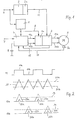
- a rectifier circuit 2 is connected to an alternating current network 6 of, for example, 230 V, which generates an output direct voltage 10 of, for example, 200-300 V from this alternating voltage without using a transformer.
- This DC output voltage 10 is fed to a power output stage 3, which has a brushless DC motor 5 directly via output lines 14a and 14b feeds.
- the power output stages 3 are controlled by means of a control circuit 4 via output lines 13a and 13b.
- This control circuit 4 including a downstream intermediate driver stage 3a, is fed from the AC network 6 by means of an auxiliary power supply 1.
- the auxiliary power supply 1 generates a low DC output voltage of e.g. 12V, for which the control circuit 4 and the intermediate driver stage 3a are designed.
- the power to be applied by the auxiliary power supply 1 is relatively low, since the power for driving the brushless DC motor 5 is provided directly from the power supply 6 by the rectifier circuit 2.
- the rectifier circuit 2 also contains a monitoring circuit 2 a, which ensures inrush current limitation and overcurrent limitation in a known manner.
- the control circuit 4 is designed in the form of an integrated circuit, as is shown, for example, in the PCT publication WO 87/02528 already mentioned.
- This control circuit contains all components for controlling the motor windings of a brushless DC motor of lower power via output lines 13a and 13b, which are connected to internal output stages of the control circuit 4.
- the pulse 11a determines the commutation phase for one of the motor windings, while the pulse pause 11b defines the commutation phase for the other motor winding.
- a triangular voltage 20 (see FIG. 2) is derived from the output signals 11 of the rotor position sensor 5a, the pulses of which lie symmetrically to the commutation phases 11a and 11b of the rotor position sensor 5a.
- the width of the triangular pulses - regardless of the speed of the motor 5 - corresponds approximately to the width of the commutation phase 11a or 11b, specifically by evaluating the voltage 12 proportional to the speed of the motor 5 and in conjunction with an external capacitor 8 as a timing element . Details of this circuit can be found in the PCT publication WO 87/02528 already mentioned.
- the control circuit 4 is supplied with a target value 7 or a reference variable which determines a threshold value 21a or 21b. If the target value 7 is low, there is, for example, a threshold value at the level of the dashed line 21a.
- the control circuit 4 has the effect that the portion of the triangular voltage 20 exceeding this threshold is output by the respective output stage of the control circuit 4 as an output signal 13a or 13b, as shown in FIG. 2 for the two output lines 13a and 13b.
- the triangular pulses 22a and 22b belong to the threshold value 21a. If the target value 7 is increased, the threshold value is lowered in the direction of the lower value 21b.
- Triangular pulses 23a and 23b of higher amplitude arise per se. The peaks of these triangular pulses do not become effective, however, since the output stages within the control circuit 4 and the power output stages 3 are already saturated. The triangular pulses of higher amplitude thus become trapezoidal pulses 23a and 23b. 2, this threshold is shown by the dashed line 24, from which the output stage transistors pass into saturation.
- the control circuit 4 thus has the effect that triangular pulses 22a and 22b of variable amplitude are generated on their output lines 13a and 13b in the respective commutation phase 11a and 11b, these pulses going into trapezoidal shape 23a and 23b at higher values. It can be seen that both the triangular pulses 22a and 22b and the trapezoidal pulses 23a and 23b lie symmetrically within the commutation phases 11a and 11b, respectively, so that there is an optimum efficiency for the direct current motor 15.
- the control circuit 4 may also contain a control circuit in order to regulate the output signals 13a, 13b or 14a, 14b depending on the setpoint 7 and a feedback speed voltage 12.
- the output stages in the control circuit 4 are normal suitable for direct operation of a DC motor with lower power.
- intermediate driver stages 3a are provided between the control circuit 4 and the power output stages 3, which effect the corresponding signal adaptation and also ensure that the output current in the lines 14a and 14b are directly proportional to the output signals 13a and 13b of the control circuit 4.
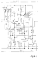
- FIG. 3 shows a power supply part
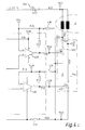
- FIG. 4 shows the speed control and the power output stages as well as intermediate driver stages and a monitoring circuit.
- the DC output voltage on line 10 is smoothed by capacitor 311, to which a discharge resistor 312 is connected in parallel.
- the mains voltage which can be tapped off at the resistor 304 is also applied to the input of the auxiliary power supply 1 via series resistors 314, 315. From there, a further capacitor 318 is connected to ground potential.
- the auxiliary power supply is also directly connected to ground potential with one or more lines.
- the smoothing capacitors 319 and 320 also connect the auxiliary power supply 1 to ground potential.
- the auxiliary power supply unit generates a voltage of approximately 12 volts on the output line 9. This is monitored by a Zener diode 316. In FIG.
- the high DC supply voltage is supplied to the stator coils of the DC motor 5 via connection point L1 via the monitoring circuit 2a (here implemented as a PTC resistor). These are connected to the associated field-effect transistors 428 and 427 of the output stage 3 by means of the line 14a and 14b.
- the control signals for the transistors 427 and 428 are derived, as already mentioned above, from the output signals of the rotor position transmitter 5a, which draws its supply voltage from the control circuit 4 and also returns its useful signals there via the line 11.
- the delta voltage is available at capacitor 419, while the actual speed value can be tapped at capacitor 8.
- the output signals of the control circuit 4 are applied to the bases of the transistors 423 and 424 via lines 13a and 13b, the bases being provided with a positive bias voltage via the resistors 408 and 409, respectively.
- Transistors 423, 424 are PNP transistors whose emitters are connected to the low supply voltage of approximately 12 volts via a common series resistor 410. Both transistors are connected to ground with a collector resistance (411.412) of approximately 3 kilohms each. The signal that can be tapped at the collectors is in each case given directly to the non-inverting inputs of the current control stages 425 or 426.
- the operational amplifiers of the current control stages 425 and 426 receive their supply voltage via the output of a restart circuit 555, which ensures a reliable restart of the motor in the event of a prolonged overload or blocking of the motor 5.
- a restart circuit 555 which ensures a reliable restart of the motor in the event of a prolonged overload or blocking of the motor 5.
- the current control stages 425 and 426 receive supply voltage for about one second, whereupon their supply voltage is switched off again for about four seconds. This gives the monitoring circuit 2a (PTC resistor) the opportunity to cool down sufficiently and to provide a nominal starting current.
- the operation of the restart circuit is based on the fact that the control circuit 4, based on the transistor 438, gives a speed-proportional trigger signal (two pulses per motor expansion), which, after further inversion via the transistor 437, means that the capacitor 435 is not appreciably via the series resistor 432 and the right arm of the double diode 434 can be charged. If these trigger pulses are absent, capacitor 435 charges up, so that the collector of transistor 437 is at an elevated potential after a few seconds and causes the restart circuit 555 to oscillate via the trigger input. This is achieved in that a discharge output of the restart circuit 555 can discharge the capacitor 435 via a discharge resistor 433 and the left arm of the double diode 434.
- the discharge takes about four times longer than the charging of the capacitor 435.
- the current regulating stages 425 and 426 are thus provided with supply voltage in an approximately 5-second cycle for about one second, and until the control circuit 4 again gives trigger pulses to the base of the transistor 438, so that the capacitor 435 can be kept discharged at all times.
Landscapes
- Engineering & Computer Science (AREA)
- Power Engineering (AREA)
- Control Of Motors That Do Not Use Commutators (AREA)
Claims (15)
- Circuit d'attaque pour un moteur à courant continu sans balai comprenant :- un étage de sortie de puissance (3) pour les enroulements du moteur à courant continu (5),- un circuit de commande (4) pour commander les étages de sortie de puissance (3) avec des signaux de sortie (13a, 13b) de forme triangulaire ou trapézoïdale, qui sont commandés par une installation de détection (5a) pour les phases de commutation et sont réglés par l'indication d'une valeur de consigne ou d'une grandeur guide (7),- une installation d'alimentation en courant (1, 2, 2a) pour l'alimentation électrique de l'étage de puissance (3) avec une tension de fonctionnement (10) redressée et pour l'alimentation électrique du circuit de commande (4),caractérisé par- un étage d'attaque intermédiaire (3a) branché entre l'étage de puissance (3) et le circuit de commande (4), qui donne aux courants de sortie (14a, 14b) de l'étage de puissance (3) une forme triangulaire ou trapézoïdale, et ceux-ci étant réglables proportionnellement aux signaux de sortie triangulaires ou trapézoïdaux (13a, 13b) du circuit de commande (4) et,- l'installation d'alimentation électrique (1, 2, 2a) fournit, pour l'alimentation électrique du circuit de commande (4), une tension de fonctionnement (9) redressée et plus faible par comparaison à la tension de fonctionnement (10) de l'étage de puissance (3), l'étage de puissance (3) étant branché sans transformateur, par un redresseur (2), aux bornes d'un réseau alternatif (6), une partie de réseau auxiliaire (1) étant prévue branchée sur les bornes du réseau alternatif (6) et la tension de fonctionnement (9) la plus faible étant disponible pour le circuit de commande (4) et pour l'étage d'attaque intermédiaire (3a).
- Circuit d'attaque selon la revendication 1,
caractérisé en ce que
l'étage d'attaque intermédiaire (3a) assure le couplage galvanique du circuit de commande (4) à l'étage de puissance (3). - Circuit d'attaque selon l'une des revendications 1 et 2,
caractérisé en ce que
le moteur à courant continu (5), sans balais, est un moteur de ventilateur à capteur de position de rotor (5a), comme installation de détection. - Circuit d'attaque selon la revendication 3,
caractérisé en ce que
le circuit de commande (4) fixe les phases de commutation du moteur de ventilateur en fonction d'un signal de sortie (11) du capteur de position (5a) du rotor. - Circuit d'attaque selon l'une des revendications 1 à 4,
caractérisé en ce que
le circuit de commande (4) permet de régler l'amplitude et/ou la durée des signaux de sortie (13a, 13b) pour commander l'étage de sortie de puissance (3). - Circuit d'attaque selon l'une des revendications 3 à 5,
caractérisé en ce que
le circuit de commande (4) est un circuit intégré comportant les éléments suivants :- un circuit d'alimentation pour l'alimentation électrique du capteur de position de rotor (5a),- un circuit pour fixer les phases de commutation des enroulements du moteur en fonction des signaux de sortie du capteur de position de rotor (5a),- un circuit de formation d'impulsions pour commander ou réguler l'amplitude et/ou la durée des signaux de sortie des différents enroulements du moteur en fonction d'une valeur de consigne (7) ou d'une grandeur guide,- des étages de puissance pour fournir les signaux de sortie destinés aux enroulements du moteur. - Circuit d'attaque selon l'une des revendications 1 à 6,
caractérisé en ce que
les signaux de sortie (13a, 13b) fournis par le circuit de commande (4) sont des impulsions et, à l'intérieur de chaque phase de commutation (11a, 11b), on a une impulsion qui, pour la faible puissance de sortie, se présente sous la forme d'une impulsion triangulaire symétrique (22a, 22b) d'amplitude variable et qui, pour une augmentation de la puissance, prend la forme d'une impulsion trapézoïdale (23a, 23b) de largeur variable. - Circuit d'attaque selon la revendication 7,
caractérisé en ce que
les impulsions triangulaires ou trapézoïdales sont situées de manière symétrique à l'intérieur des phases de commutation (11a, 11b). - Circuit d'attaque selon l'une des revendications 1 à 8,
caractérisé en ce que
la partie de réseau auxiliaire (1) est un circuit intégré qui fournit, à l'aide d'un commutateur cadencé et d'un condensateur de charge, une tension redressée, régulée et filtrée à partir du réseau de courant alternatif (6). - Circuit d'attaque selon l'une des revendications 1 à 9,
caractérisé en ce que
le redresseur (2) comporte un circuit de surveillance (2a) pour limiter le courant de branchement et le courant de dépassement pour l'étage de puissance (3). - Circuit d'attaque selon l'une des revendications 1 à 10,
caractérisé par
un circuit de redémarrage qui fournit une tension d'alimentation distincte à l'étage d'attaque intermédiaire (3a), cette tension d'alimentation distincte contenant soit une valeur nominale dans la mesure où le moteur se trouve dans sa phase de fonctionnement régulière, soit la tension d'alimentation séparée fournie d'une manière intermittente à l'étage d'attaque intermédiaire (3a) dans la mesure où le moteur est bloqué ou en surcharge. - Circuit d'attaque selon la revendication 11,
caractérisé en ce que
le circuit de redémarrage reçoit une suite d'impulsions de déclenchement, le signal de sortie du circuit de redémarrage ayant un niveau de tension prédéfini dans la mesure où les impulsions de déclenchement présentent une fréquence supérieure à une fréquence limite prédéterminée, et le signal de sortie du circuit de redémarrage présentant un autre niveau de tension prédéfini dans la mesure où les impulsions de déclenchement ont une fréquence plus faible qu'une fréquence limite prédéterminée, le circuit de redémarrage ayant un composant de commande de temps (555), une résistance de charge (432), une résistance de décharge (433), un condensateur (435), des diodes de découplage (434), un déchargeur (437) et un amplificateur (438). - Circuit d'attaque selon l'une des revendications 1 à 12,
caractérisé en ce que
l'étage d'attaque intermédiaire (3a) comporte pour chaque signal de sortie (13a, 13b) du circuit de commande (4), un étage amplificateur à transistor (423, 424) dans le circuit d'émetteur avec, en aval, un étage de régulation de courant (425, 426), une sortie de l'étage de régulation de courant (425, 426) étant couplée à une entrée de commande d'un étage de sortie de puissance (3), associé. - Circuit d'attaque selon la revendication 13,
caractérisé en ce que
l'étage de régulation de courant (425, 426) est un amplificateur opérationnel à réaction dont l'entrée non inversée (+) est reliée à une sortie du circuit d'émetteur de l'amplificateur à transistor (423, 424), dont l'entrée inversée (-) est reliée à la sortie de l'amplificateur opérationnel par une résistance de réaction, et dont la sortie est couplée à l'entrée de commande de l'étage de sortie de puissance (3). - Circuit d'attaque selon la revendication 14,
caractérisé par
une résistance de collecteur comme résistance de mesure d'intensité (415, 416) branchée entre le potentiel de référence et l'entrée non inversée (+) de l'amplificateur opérationnel (425, 426).
Applications Claiming Priority (2)
| Application Number | Priority Date | Filing Date | Title |
|---|---|---|---|
| DE4019338A DE4019338A1 (de) | 1990-06-18 | 1990-06-18 | Treiberschaltung fuer einen buerstenlosen gleichstrommotor |
| DE4019338 | 1990-06-18 |
Publications (2)
| Publication Number | Publication Date |
|---|---|
| EP0467085A1 EP0467085A1 (fr) | 1992-01-22 |
| EP0467085B1 true EP0467085B1 (fr) | 1997-01-08 |
Family
ID=6408576
Family Applications (1)
| Application Number | Title | Priority Date | Filing Date |
|---|---|---|---|
| EP91110041A Expired - Lifetime EP0467085B1 (fr) | 1990-06-18 | 1991-06-18 | Circuit d'attaque pour moteur à courant continu sans balai |
Country Status (2)
| Country | Link |
|---|---|
| EP (1) | EP0467085B1 (fr) |
| DE (2) | DE4019338A1 (fr) |
Families Citing this family (10)
| Publication number | Priority date | Publication date | Assignee | Title |
|---|---|---|---|---|
| DE4310260C1 (de) * | 1993-03-30 | 1994-09-08 | Bosch Gmbh Robert | Elektronische Steuervorrichtung für einen elektronisch kommutierten Gleichstrommotor (EC-Motor) |
| DE59405829D1 (de) * | 1993-09-15 | 1998-06-04 | Papst Motoren Gmbh & Co Kg | Anordnung mit einem über eine Halbleiteranordnung kommutierten kollektorlosen Gleichstrommotor |
| DE4432530A1 (de) * | 1994-09-13 | 1996-03-14 | Bosch Gmbh Robert | Schaltung und Verfahren für die Ansteuerung eines bürstenlosen Gleichstrommotors |
| DE59705197D1 (de) * | 1996-06-07 | 2001-12-06 | Papst Motoren Gmbh & Co Kg | Anordnung mit einem elektronisch kommutierten motor |
| DE59705198D1 (de) * | 1996-06-07 | 2001-12-06 | Papst Motoren Gmbh & Co Kg | Anordnung mit einem elektronisch kommutierten motor |
| DE19631517A1 (de) * | 1996-08-03 | 1998-02-05 | Wacker Werke Kg | Von einem Elektromotor angetriebenes, an Einphasenwechselstrom anschließbares, drehzahlvariables, handgehaltenes Elektrowerkzeug |
| EP0963034A1 (fr) * | 1998-06-05 | 1999-12-08 | Hsin-Mao Hsieh | Circuit de pilotage de moteur à courant continu sans balais pour ventilateur avec détection de signal |
| DE20105050U1 (de) * | 2000-05-27 | 2001-06-28 | Papst-Motoren GmbH & Co. KG, 78112 St Georgen | Motoranordnung |
| DE10150448A1 (de) * | 2001-10-12 | 2003-04-30 | Conti Temic Microelectronic | Verfahren zur Steuerung eines elektronisch kommutierten Motors |
| ITMI20081600A1 (it) * | 2008-09-09 | 2010-03-10 | Cross Technology S R L | Sistema attuatore-sensore |
Citations (1)
| Publication number | Priority date | Publication date | Assignee | Title |
|---|---|---|---|---|
| EP0084156A1 (fr) * | 1981-12-23 | 1983-07-27 | Papst-Motoren GmbH & Co. KG | Moteur à courant continu sans collecteur |
Family Cites Families (3)
| Publication number | Priority date | Publication date | Assignee | Title |
|---|---|---|---|---|
| US4052650A (en) * | 1972-07-26 | 1977-10-04 | Danfoss A/S | Starting device for a single-phase motor |
| DE3537403C2 (de) * | 1985-10-21 | 1995-06-01 | Papst Motoren Gmbh & Co Kg | Kollektorloser Gleichstrommotor mit oder für einen Lüfter |
| US4827196A (en) * | 1987-12-03 | 1989-05-02 | E. I. Du Pont De Nemours And Company | Motor control arrangement |
-
1990
- 1990-06-18 DE DE4019338A patent/DE4019338A1/de not_active Withdrawn
-
1991
- 1991-06-18 EP EP91110041A patent/EP0467085B1/fr not_active Expired - Lifetime
- 1991-06-18 DE DE59108461T patent/DE59108461D1/de not_active Expired - Fee Related
Patent Citations (1)
| Publication number | Priority date | Publication date | Assignee | Title |
|---|---|---|---|---|
| EP0084156A1 (fr) * | 1981-12-23 | 1983-07-27 | Papst-Motoren GmbH & Co. KG | Moteur à courant continu sans collecteur |
Also Published As
| Publication number | Publication date |
|---|---|
| EP0467085A1 (fr) | 1992-01-22 |
| DE4019338A1 (de) | 1991-12-19 |
| DE59108461D1 (de) | 1997-02-20 |
Similar Documents
| Publication | Publication Date | Title |
|---|---|---|
| DE68910077T2 (de) | Elektronische steuerschaltungen, elektronisch geschaltete motorsysteme und verfahren. | |
| EP0425479B1 (fr) | Commande de moteur à courant continu sans collecteur, plus spécialement pour actionner un ventilateur | |
| DE69618751T2 (de) | Stromversorgungsanlage für Fahrzeug | |
| EP0739084B1 (fr) | Procédé de commande ou réglage d'un moteur électrique et dispositif pour mettre en oeuvre ce procédé | |
| DE69535329T2 (de) | Lasttreibervorrichtung | |
| DE19506587C2 (de) | Anordnung zum Unterdrücken der höheren Oberschwingungen des Stroms einer Energiequelle | |
| DE3934139A1 (de) | Elektronische steuerschaltung fuer einen buerstenlosen gleichstrommotor | |
| DE3836516A1 (de) | Gleichstrommotor-geschwindigkeitssteuerung mit schutzvorrichtung | |
| DE10235293A1 (de) | Verfahren zur Steuerung der Kommutierung bei einem elektronisch kommutierenden Motor, und elektronisch kommutierter Motor zur Durchführung eines solchen Verfahrens | |
| EP0467085B1 (fr) | Circuit d'attaque pour moteur à courant continu sans balai | |
| DE69000330T2 (de) | Elektrische generator-anlasservorrichtung, insbesondere zur anwendung als generator und anlasser fuer kraftfahrzeuge. | |
| EP0247409B1 (fr) | Alimentation à commutation avec convertisseur à courant continu à découpage sur le primaire | |
| EP0650248A2 (fr) | Bloc d'alimentation | |
| DE3044150C2 (de) | Zusatzgerät zu einem Standard-Spannungsregler einer Kraftfahrzeug-Lichtmaschine | |
| DE2842923A1 (de) | Transistorisierte zuendanlage | |
| DE4120047C2 (de) | Steuergerät für einen Wechselstromgenerator | |
| EP0903008B1 (fr) | Dispositif a moteur commute electroniquement | |
| DE2746111C3 (de) | Schaltungsanordnung zum Regeln der Drehzahl eines Elektromotors | |
| EP0727062A1 (fr) | Alimentation a decoupage | |
| DE19652622A1 (de) | Getaktete Endstufenschaltung zur Steuerung oder Regelung induktiver Lasten | |
| EP1427095A2 (fr) | Moteur électrique à commutation électronique | |
| DE4323504B4 (de) | Schaltung zur Bestromung eines bürstenlosen Gleichstrommotors | |
| DE4311533B4 (de) | Ansteuerschaltung für einen kollektorlosen Gleichstrommotor | |
| DE3040459C2 (de) | Spannungsregler für Wechselstrom-, insbesondere Drehstromgeneratoren zum Aufladen einer Batterie | |
| DE19732095A1 (de) | Schaltungsanordnung zum Ansteuern eines Motors mit einer Überlasterkennungseinrichtung |
Legal Events
| Date | Code | Title | Description |
|---|---|---|---|
| PUAI | Public reference made under article 153(3) epc to a published international application that has entered the european phase |
Free format text: ORIGINAL CODE: 0009012 |
|
| AK | Designated contracting states |
Kind code of ref document: A1 Designated state(s): DE FR GB IT |
|
| 17P | Request for examination filed |
Effective date: 19920508 |
|
| 17Q | First examination report despatched |
Effective date: 19920915 |
|
| RAP1 | Party data changed (applicant data changed or rights of an application transferred) |
Owner name: PAPST LICENSING GMBH |
|
| GRAG | Despatch of communication of intention to grant |
Free format text: ORIGINAL CODE: EPIDOS AGRA |
|
| GRAG | Despatch of communication of intention to grant |
Free format text: ORIGINAL CODE: EPIDOS AGRA |
|
| GRAH | Despatch of communication of intention to grant a patent |
Free format text: ORIGINAL CODE: EPIDOS IGRA |
|
| GRAH | Despatch of communication of intention to grant a patent |
Free format text: ORIGINAL CODE: EPIDOS IGRA |
|
| GRAA | (expected) grant |
Free format text: ORIGINAL CODE: 0009210 |
|
| AK | Designated contracting states |
Kind code of ref document: B1 Designated state(s): DE FR GB IT |
|
| PG25 | Lapsed in a contracting state [announced via postgrant information from national office to epo] |
Ref country code: IT Free format text: LAPSE BECAUSE OF FAILURE TO SUBMIT A TRANSLATION OF THE DESCRIPTION OR TO PAY THE FEE WITHIN THE PRE;WARNING: LAPSES OF ITALIAN PATENTS WITH EFFECTIVE DATE BEFORE 2007 MAY HAVE OCCURRED AT ANY TIME BEFORE 2007. THE CORRECT EFFECTIVE DATE MAY BE DIFFERENT FROM THE ONE RECORDED.SCRIBED TIME-LIMIT Effective date: 19970108 Ref country code: FR Effective date: 19970108 |
|
| REF | Corresponds to: |
Ref document number: 59108461 Country of ref document: DE Date of ref document: 19970220 |
|
| GBT | Gb: translation of ep patent filed (gb section 77(6)(a)/1977) |
Effective date: 19970321 |
|
| EN | Fr: translation not filed | ||
| PLBE | No opposition filed within time limit |
Free format text: ORIGINAL CODE: 0009261 |
|
| STAA | Information on the status of an ep patent application or granted ep patent |
Free format text: STATUS: NO OPPOSITION FILED WITHIN TIME LIMIT |
|
| 26N | No opposition filed | ||
| REG | Reference to a national code |
Ref country code: GB Ref legal event code: IF02 |
|
| PGFP | Annual fee paid to national office [announced via postgrant information from national office to epo] |
Ref country code: DE Payment date: 20090811 Year of fee payment: 19 Ref country code: GB Payment date: 20090416 Year of fee payment: 19 |
|
| GBPC | Gb: european patent ceased through non-payment of renewal fee |
Effective date: 20100618 |
|
| PG25 | Lapsed in a contracting state [announced via postgrant information from national office to epo] |
Ref country code: DE Free format text: LAPSE BECAUSE OF NON-PAYMENT OF DUE FEES Effective date: 20110101 |
|
| PG25 | Lapsed in a contracting state [announced via postgrant information from national office to epo] |
Ref country code: GB Free format text: LAPSE BECAUSE OF NON-PAYMENT OF DUE FEES Effective date: 20100618 |