EP0739227B1 - Wurfscheibe - Google Patents
Wurfscheibe Download PDFInfo
- Publication number
- EP0739227B1 EP0739227B1 EP95905108A EP95905108A EP0739227B1 EP 0739227 B1 EP0739227 B1 EP 0739227B1 EP 95905108 A EP95905108 A EP 95905108A EP 95905108 A EP95905108 A EP 95905108A EP 0739227 B1 EP0739227 B1 EP 0739227B1
- Authority
- EP
- European Patent Office
- Prior art keywords
- discus
- luminous
- luminous bodies
- disposed
- bodies
- Prior art date
- Legal status (The legal status is an assumption and is not a legal conclusion. Google has not performed a legal analysis and makes no representation as to the accuracy of the status listed.)
- Expired - Lifetime
Links
- 241000950638 Symphysodon discus Species 0.000 title claims abstract description 82
- HOQADATXFBOEGG-UHFFFAOYSA-N isofenphos Chemical compound CCOP(=S)(NC(C)C)OC1=CC=CC=C1C(=O)OC(C)C HOQADATXFBOEGG-UHFFFAOYSA-N 0.000 title claims abstract description 80
- 239000000463 material Substances 0.000 claims description 8
- 230000003213 activating effect Effects 0.000 claims description 6
- 230000005855 radiation Effects 0.000 claims description 3
- 239000012780 transparent material Substances 0.000 claims description 3
- 230000005611 electricity Effects 0.000 claims 1
- 230000000694 effects Effects 0.000 description 8
- 230000003287 optical effect Effects 0.000 description 2
- 238000010276 construction Methods 0.000 description 1
- 239000013078 crystal Substances 0.000 description 1
- 238000010586 diagram Methods 0.000 description 1
- 230000002349 favourable effect Effects 0.000 description 1
- 239000003292 glue Substances 0.000 description 1
- QSHDDOUJBYECFT-UHFFFAOYSA-N mercury Chemical compound [Hg] QSHDDOUJBYECFT-UHFFFAOYSA-N 0.000 description 1
- 229910052753 mercury Inorganic materials 0.000 description 1
- 239000010453 quartz Substances 0.000 description 1
- VYPSYNLAJGMNEJ-UHFFFAOYSA-N silicon dioxide Inorganic materials O=[Si]=O VYPSYNLAJGMNEJ-UHFFFAOYSA-N 0.000 description 1
Images


Classifications
-
- F—MECHANICAL ENGINEERING; LIGHTING; HEATING; WEAPONS; BLASTING
- F21—LIGHTING
- F21V—FUNCTIONAL FEATURES OR DETAILS OF LIGHTING DEVICES OR SYSTEMS THEREOF; STRUCTURAL COMBINATIONS OF LIGHTING DEVICES WITH OTHER ARTICLES, NOT OTHERWISE PROVIDED FOR
- F21V33/00—Structural combinations of lighting devices with other articles, not otherwise provided for
- F21V33/008—Leisure, hobby or sport articles, e.g. toys, games or first-aid kits; Hand tools; Toolboxes
-
- A—HUMAN NECESSITIES
- A63—SPORTS; GAMES; AMUSEMENTS
- A63H—TOYS, e.g. TOPS, DOLLS, HOOPS OR BUILDING BLOCKS
- A63H33/00—Other toys
- A63H33/18—Throwing or slinging toys, e.g. flying disc toys
-
- F—MECHANICAL ENGINEERING; LIGHTING; HEATING; WEAPONS; BLASTING
- F21—LIGHTING
- F21Y—INDEXING SCHEME ASSOCIATED WITH SUBCLASSES F21K, F21L, F21S and F21V, RELATING TO THE FORM OR THE KIND OF THE LIGHT SOURCES OR OF THE COLOUR OF THE LIGHT EMITTED
- F21Y2115/00—Light-generating elements of semiconductor light sources
- F21Y2115/10—Light-emitting diodes [LED]
Definitions
- the present invention relates to a discus according to the preamble of claim 1.
- a discus of this type is known under the name "Frisbee”. It is a playing device usually made of plastic material that can be set rotating about its central axis by hand and thereby thrown stably over relatively far distances.
- DE 34 25 037 A1 describes a discus according to the preamble of claim 1.
- This known discus includes some groups of light-emitting diodes connected in series, the diodes of each group being arranged in the form of a ring. All diodes of a specific ring are controlled simultaneously and in the same fashion by an electromechanical circuit device comprising mercury switches or flip-flops.
- an electromechanical circuit device comprising mercury switches or flip-flops.
- US-A-4,929,212 discloses a discus having a simple luminous and acoustic device which is controlled by switches activated by centrifugal forces during the flight of the discus.
- US-A-4,307,538 describes a lighting system for disc toys including a circuit device consisting of a plurality of logic elements, resistors etc. Therefore, this known circuit device is of heavy weight and does not meet the requirements of little dimensions. This known discus may only ensure that a continuous light streak is visible.
- US-A-3,720,018 discloses a disc-shaped flight toy which is illuminated for night flying. Rays from the central light object of the toy are deflected outwardly and radially so as to illuminate either the material of the toy itself, internally, or to reflect light from one or both opposite services thereof. Such a flight toy is also described in US-A-3,786,246 showing a disc-shaped body terminating at its periphery in a downwardly pointing rim receiving lighting means in the form of a plurality of regularly spaced lamps.
- the invention is based on the problem of providing a discus of the above-mentioned type which provides a significantly increased attractivity and variability the signal patterns as compared with known discuses and which allows to easy change the signal patterns and an increased efficiency insuring a long playtime.
- the discus according to the invention is provided with a circuit device including microprocessor control means controlling each luminous body individually and according to the use to software, and a time function element activating the luminous bodies in pulsed fashion with pulsed duration of at least 30 %.
- the discus has a significantly raised attractivity and variability by replacing the known wiring of the individual electric components by a "software solution” using a microprocessor. Each luminous body can be individually and separately controlled by the microprocessor control means.
- the originally relatively simple toy “Frisbee” is therefore developed further to a "hightech article” incorporating a particular great number of different signal patterns without requiring changing the hardware components.
- the discus raises therefore the attractivity for the player and allows the manufacturer to change signal patterns without changing the hardware components.
- a further advantage results from the time function element activating the luminous bodies in pulsed fashion with a pulsed duration of at least 30 %. If luminous bodies such as LEDs are driven with a pulse width of 30 % (or more), the human eye no longer perceives the LEDs lighting up and going out but sees the LED ligth as steady light. In other words, the dark phases between the lighting-up phases cannot be perceived any longer. On the other hand, such a pulse duration saves current at the same time since the LEDs are only switched on e.g. 30 % of the total time. This prolongs considerably the working life of normal batteries or that of accumulators between charging times.
- the effects generated by the discus can be extremely diverse depending on the design of the luminous device. For example it is possible to make individual, in particular different-colored, luminous bodies of the luminous device light up by turns. These luminous bodies can also be disposed on the discus in such a way that they form a certain motif. The luminous bodies can furthermore be driven in such a way as to light up according to a certain time scheme and/or scheme influencing the intensity of luminous power. The luminous bodies can light up continuously or intermittently, for example flashing like a stroboscope. If a suitable acoustic device is provided on the discus a great variety of acoustic effects can be produced either alternatively or in addition to the above-mentioned optical effects.
- the luminous and/or acoustic device permits the discus to be followed much more easily and better during its flight, whereby the colored play of lights, for example, and possible sound effects considerably increase its attractiveness both for the user and for any onlooker.
- the hardware components necessary for realizing the inventive luminous and/or acoustic device have such low weight and small dimensions that they do not impair the flying qualities of the discus. It has instead turned out that the slight increase in weight often actually improves the flying qualities.
- the luminous and/or acoustic device can be disposed on the underside, top or both sides of the discus. If the luminous device is disposed on the underside of the discus the bent-down edge of the discus already offers a certain protection for the electric device.
- the luminous device it is also possible for the luminous device to be disposed in a depression in the discus, in which case the device can be inserted in the depression from the top side of the discus. This provides excellent mechanical protection for the electric device in a simple way.
- the luminous device can also be disposed in a raised area on the top side of the discus or on each side, i.e. protruding beyond the top side and underside.
- the energy source for the luminous device can be one-way or rechargeable batteries to be connected to a charging set via a plug socket provided on the luminous device, or alternative energy sources such as solar cells for example.
- the luminous device has a plurality of luminous bodies which are spaced apart.
- the luminous bodies can realize a great variety of motifs in a simple way.
- the luminous bodies are disposed in a circle about the central axis of the discus and comprise small incandescent bulbs, light-emitting diodes or flash bulbs.
- At least the areas of the discus adjacent the luminous bodies are advantageously made of a transparent material.
- the luminous effects are visible on both sides of the discus. This is of advantage in particular since the discus frequently flies at a certain inclination to the horizontal so that both the top side and the underside are visible during flight. It is also possible in this case to embed the electric device completely within the plastic material of the discus which permits particularly good protection for the electric device.
- the luminous bodies can be surrounded at least partly by an opaque material provided with diaphragmlike openings for selective exit of light.
- the luminous device advantageously has reflecting elements preferably disposed in adjustable fashion for influencing the angle of radiation.
- the discus is provided with an electrically operated acoustic device comprising at least one acoustic element connected with the electric or electronic circuit device for activating the acoustic elements according to a predetermined time scheme and/or scheme influencing the volume and/or tone pitch.
- the circuit device has a time function element serving as a clock unit and emitting an in particular rectangular current or voltage pulse, said element being connected with a decade counter driving the luminous means.
- the luminous and/or acoustic means are driven by means of a sensor detecting the direction of rotation, rotational speed, ambient light conditions and/or flying speed of the discus.
- Fig. 1 shows discus 1 known as a "Frisbee" having a bowl or dish shape.
- Luminous device 2 is fastened to the underside of discus 1 and has carrier 3 for luminous bodies 4 and electric circuit device 5 with a simple rectangular pulse time function element, a decade counter or a suitably programmed microprocessor.
- Luminous device 2 is disposed axially to central axis 6 of discus 1 so that the mass center of luminous device 2 lies in central axis 6 or at least as close as possible thereto. Luminous device 2 can be fastened to discus 1 by glue.
- Luminous bodies 4 protrude radially outward from carrier 3 and are spaced apart in a circle about central axis 6.
- Luminous bodies 4 can comprise permanently wired light-emitting diodes, flash bulbs or small incandescent bulbs received in corresponding sockets in carrier 3.
- Luminous bodies 4 are supplied with energy by one or more rechargeable, small-sized batteries (not shown) of luminous device 2.
- plug socket 7 is provided on the top side of luminous device 2 into which a corresponding plug of a charging set (not shown) can be inserted.
- Plug socket 7 can be received within projection 8 of luminous device 2 that extends upward through circular gap 9 within discus 1.
- Electric circuit device 5 drives luminous bodies 4 in such a way that they light up according to the predetermined time scheme and/or scheme influencing the intensity of luminous power.
- a switch (not shown) is also provided on luminous device 2 for switching the luminous device on and off.
- Discus 1 can be made of a plastic material which is transparent at least in the area of luminous bodies 4 so that the lighting up of luminous bodies 4 can be perceived not only from the underside of discus 1 but also through discus 1 from its top side. It is also possible to metalize the underside of discus 1 to increase the luminous effect of luminous bodies 4 downward.
- discus 1 has rotationally symmetric, central depression 9 which is open toward the top.
- Luminous device 2 is inserted into depression 9 from above.
- the opening of depression 9 is closed by cover plate 10 whose top side is flush with the top side of the bordering areas of discus 1.
- Plug socket 7 can extend through cover plate 10, as shown, so that the latter need not be removed for charging the batteries. To prevent dirt or moisture from entering plug socket 7 the latter can be closed by suitable stopper 11.
- the electric circuit device is received within carrier 3.
- at least the area of depression 9 and/or cover plate 10 are also made of a transparent material so that the lighting up of luminous bodies 4 is visible through the material.
- luminous bodies 4 are disposed on the top side of discus 1 while electric circuit device 5 is located on its underside.
- Luminous bodies 4 and carrier 3 are covered by transparent cap 13 so that luminous bodies 4 shine through to the outside, on the one hand, and are protected, on the other hand.
- Cap 14 drawn over electric circuit device 5 ensures protection of the electric or electronic components.
- Fig. 4 shows discus 1 wherein luminous bodies 4 are disposed both on the top side and on the underside of discus 1. Electric circuit device 5 is likewise located on the underside of discus 1.
- Fig. 5 shows a further embodiment of discus 1 wherein reflecting elements 15 are disposed within bottom cap 14 to influence in a desired way the angle of emission of the light radiated by luminous bodies 4.
- reflecting elements 15 are expediently disposed in adjustable fashion.
- Fig. 6 shows a further embodiment of discus 1 wherein upper cap 13 and lower cap 14 are shown, not in cross section as in Figs. 3 to 5, but in a side view.
- cap 14 is made of an opaque material.
- cap 14 has slotlike light exit openings 16 that have the effect of a diaphragm and limit the angle of emission.
- slot-like light exit openings one can also provide ones with other cross-sectional shapes, for example circular light exit openings.
- Figs. 7A to 7C show various possibilities for disposing luminous bodies 4 on carrier 3.
- luminous bodies 4 are disposed with their feet parallel to carrier 3, for example a printed board, and fastened thereto.
- luminous bodies 4 are disposed perpendicular to carrier 3, the feet of luminous body 4 piercing carrier 3 and being fastened thereto.
- luminous bodies 4 are disposed at certain angle ⁇ to carrier 3.
- angle ⁇ is 45° but it can also be different depending on the desired angle of radiation of luminous bodies 4.
- carrier 3 has holding plate 17 which is beveled at angle ⁇ and serves as a support for the feet of luminous bodies 4.
- Discuses 1 shown in Figs. 1 to 6 can be provided with acoustic device 12 (shown for clarity's sake only in Fig. 1) having one or more acoustic elements, for example small loudspeakers, which are driven in the desired way by electric circuit device 5.
- acoustic device 12 shown for clarity's sake only in Fig. 1
- acoustic elements for example small loudspeakers
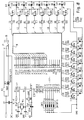
- Fig. 8 shows an electric circuit device wherein the switching functions are realized by means of microprocessor IC 5.
- the clock frequency of microprocessor IC 5 is given by reference counter 18, for example a quartz crystal.
- the supply voltage is 4.8 volts and is delivered by battery BT 1 which can likewise be charged via socket 19.
- Microprocessor IC 5 is used to drive altogether sixteen different light-emitting diodes D2 to D17 via lines L1 to L16, resistors R3 to R18 and transistors T1 to T16. Lines L1 to L16 are shown in Fig. 8 partly in the form of bus 18.
- the microprocessor requires software involving about 4 KB. Ports P 0.0 to P 0.7 and P 2.0 to P 2.7 serve to drive the light-emitting diodes. Port P 1.0 to P 1.7 is utilized as a control and start strip. Pin 1 starts the program selected in pins 3 to 7 which lasts about 2 minutes. Before this time has lapsed the program can be canceled by the key button on pin 1. The direction of the light-emitting diodes is controlled via pin 3 and their speed via pin 4. Eight basic programs can be called via pins 5 to 7.
Landscapes
- Engineering & Computer Science (AREA)
- General Engineering & Computer Science (AREA)
- Toys (AREA)
- Non-Portable Lighting Devices Or Systems Thereof (AREA)
- Magnetic Record Carriers (AREA)
- Percussion Or Vibration Massage (AREA)
- Sorption Type Refrigeration Machines (AREA)
- Circuit Arrangement For Electric Light Sources In General (AREA)
- Agricultural Chemicals And Associated Chemicals (AREA)
- Electrophonic Musical Instruments (AREA)
Claims (18)
- Diskus mit einer schalen- oder schüsselförmigen Gestalt, der mit einer elektrisch betriebenen Leuchteinrichtung (2) versehen ist, einschließlich einer Mehrzahl von Leuchtkörpern (4), die mit einer elektrisch oder elektronischen Schalteinrichtung zur Aktivierung der Leuchtkörper (4) ausgerichtet sind, entsprechend einem vorgegebenen Zeitschema und/oder einem Schema, welches die Intensität der Leuchtkraft beeinflußt,
dadurch gekennzeichnet, daß
die Schalteinrichtung eine Mikroprozessorsteuereinrichtung umfaßt, zur Steuerung eines jeden Leuchtkörpers (4) individuell und entsprechend der eingesetzten Software sowie ein Zeitfunktionselement (IC1, IC2), welches die Leuchtkörper (4) aktiviert in einer gepulsten Weise mit einer Impulsdauer von mindestens 30 %. - Diskus nach Anspruch 1, dadurch gekennzeichnet, daß sich die Einrichtung (2) auf der unteren und/oder der oberen Seite des Diskus (1) befindet.
- Diskus nach Anspruch 2, dadurch gekennzeichnet, daß sich die Einrichtung (2) in einer Vertiefung (9) des Diskus (1) befindet.
- Diskus nach Anspruch 2, dadurch gekennzeichnet, daß die Einrichtung sich in einem angehobenen Bereich auf der Oberseite des Diskus (1) befindet.
- Diskus nach Anspruch 1, dadurch gekennzeichnet, daß das Massenzentrum der Einrichtung (2) im Zentrum des Diskus (1) angeordnet ist.
- Diskus nach Anspruch 1, dadurch gekennzeichnet, daß das Massenzentrum (2) mit Elektrizität durch wiederaufladbare Batterien versorgt ist.
- Diskus nach Anspruch 6, dadurch gekennzeichnet, daß die Batterien an eine Aufladeinrichtung über einen Stecksockel (7) anschließbar sind, mit welchem die Einrichtung (2) ausgerüstet ist.
- Diskus nach Anspruch 1, dadurch gekennzeichnet, daß die Einrichtung (2) durch Solarenergie betreibbar ist.
- Diskus nach Anspruch 1, dadurch gekennzeichnet, daß die Leuchtkörper (4) in einem Abstand voneinander angeordnet sind.
- Diskus nach Anspruch 9, dadurch gekennzeichnet, daß die Leuchtkörper (4) in einem Kreisbogen um die Mittelachse (6) des Diskus (1) angeordnet sind.
- Diskus nach Anspruch 1, dadurch gekennzeichnet, daß die Leuchtkörper (4) kleine Glühbimen und/oder lichtemittierende Dioden und/oder Blitzlichtbimen umfassen.
- Diskus nach Anspruch 9, dadurch gekennzeichnet, daß die Bereiche des Diskus (1), angrenzend an die Leuchtkörper (4) aus einem transparenten Material bestehen.
- Diskus nach Anspruch 9, dadurch gekennzeichnet, daß die Leuchtkörper (4) zumindest teilweise umgeben sind von einem undurchsichtigen Material, welches mit membranähnlichen Öffnungen versehen ist, zum selektiven Lichtaustritt.
- Diskus nach Anspruch 1, dadurch gekennzeichnet, daß die Leuchteinrichtung (2) reflektierende Elemente (15) besitzt, die in einer einstellbaren Weise angeordnet sind zur Beeinflussung des Abstrahlungswinkels.
- Diskus nach Anspruch 1, dadurch gekennzeichnet, daß der Diskus (1) mit einer elektrisch betriebenen akustischen Einrichtung (12) versehen ist, mit mindestens einem akustischen Element, welches an eine elektrische oder elektronische Schalteinrichtung angeschlossen ist, zur Aktivierung der akustischen Elemente, entsprechend einem vorbestimmten Zeitschema und/oder einem Schema zur Beeinflussung der Lautstärke und/oder der Tonhöhe.
- Diskus nach einem der Ansprüche 1 bis 15, dadurch gekennzeichnet, daß das Zeitfunktionselement (IC1, IC2) die Leuchtkörper (4) aktiviert mit einer Impulsdauer von 30 bis 50 %.
- Diskus nach einem der Ansprüche 1 bis 16, dadurch gekennzeichnet, daß das Zeitfunktionselement (IC2) als Zeitgebereinheit wirkt und einen im wesentlichen rechteckförmigen Strom- oder Spannungsimpuls emittiert, wobei das Element an einen Zehnergruppenzähler (IC3) angeschlossen ist, der die Leuchteinrichtung aktiviert.
- Diskus nach einem der Ansprüche 1 bis 17, dadurch gekennzeichnet, daß die Leuchtkörper (4) und/oder die akustischen Elemente durch einen Sensor aktivierbar sind, der die Rotationsrichtung und/oder die Rotationsgeschwindigkeit und/oder die Umgebungslichtbedingungen und/oder die Fluggeschwindigkeit des Diskus (1) erfaßt.
Applications Claiming Priority (3)
| Application Number | Priority Date | Filing Date | Title |
|---|---|---|---|
| DE4400191 | 1994-01-05 | ||
| DE4400191A DE4400191C2 (de) | 1994-01-05 | 1994-01-05 | Wurfscheibe |
| PCT/EP1994/004299 WO1995018660A1 (en) | 1994-01-05 | 1994-12-23 | A discus |
Publications (2)
| Publication Number | Publication Date |
|---|---|
| EP0739227A1 EP0739227A1 (de) | 1996-10-30 |
| EP0739227B1 true EP0739227B1 (de) | 1998-03-18 |
Family
ID=6507497
Family Applications (1)
| Application Number | Title | Priority Date | Filing Date |
|---|---|---|---|
| EP95905108A Expired - Lifetime EP0739227B1 (de) | 1994-01-05 | 1994-12-23 | Wurfscheibe |
Country Status (7)
| Country | Link |
|---|---|
| EP (1) | EP0739227B1 (de) |
| AT (1) | ATE164092T1 (de) |
| AU (1) | AU1385095A (de) |
| DE (2) | DE4400191C2 (de) |
| DK (1) | DK0739227T3 (de) |
| ES (1) | ES2117848T3 (de) |
| WO (1) | WO1995018660A1 (de) |
Cited By (1)
| Publication number | Priority date | Publication date | Assignee | Title |
|---|---|---|---|---|
| CN108260542A (zh) * | 2018-01-05 | 2018-07-10 | 深圳市沃特沃德股份有限公司 | 飞盘控制方法和装置 |
Families Citing this family (10)
| Publication number | Priority date | Publication date | Assignee | Title |
|---|---|---|---|---|
| DE29518640U1 (de) * | 1995-11-24 | 1997-03-27 | Loupi & Blinkie Elektronik GmbH, 40227 Düsseldorf | Schaltungsanordnung zum zyklischen Ansteuern mehrerer Verbraucher |
| US5611720A (en) * | 1996-02-20 | 1997-03-18 | Alien Warper, Inc. | Flying disc toy with lighting system |
| DE19636476A1 (de) * | 1996-09-07 | 1998-03-12 | Jochen Ezer | Wurfspielzeug mit Licht- und Toneffekten |
| US6270391B1 (en) * | 1999-02-02 | 2001-08-07 | Tryggvi Emilsson | Lighting system for rotating object |
| GB9903113D0 (en) * | 1999-02-11 | 1999-04-07 | Mgx International Ltd | Programmable display device |
| AU2003301822A1 (en) * | 2002-11-01 | 2004-06-07 | Mattel, Inc. | Improved remotely controlled toy vehicles with light(s) |
| US7234992B2 (en) * | 2002-11-01 | 2007-06-26 | Mattel, Inc. | Remotely controlled toy vehicles with light(s) |
| DE10321945A1 (de) * | 2003-05-15 | 2004-12-09 | Flügge, Erhardt J. | Spielgerät |
| US7128698B2 (en) * | 2004-11-22 | 2006-10-31 | Tessema Dosho Shifferaw | Air resistance exercise device and method |
| US11813545B2 (en) * | 2012-02-27 | 2023-11-14 | Evans Walter Abarzua-Kocking | Unique flying disk with a handle at the center downwards |
Family Cites Families (10)
| Publication number | Priority date | Publication date | Assignee | Title |
|---|---|---|---|---|
| DE8236868U1 (de) * | 1983-06-16 | Ahlering, geb. Buck, Cornelia, 2000 Hamburg | Kreisförmige Wurfscheibe | |
| DE8329055U1 (de) * | 1984-04-19 | Schulz, Hagen | Leuchtende Solar-Wurfscheibe | |
| US3720018A (en) * | 1971-03-25 | 1973-03-13 | H Peterson | Lighted disk-type flight toy and components thereof |
| US3786246A (en) * | 1972-03-24 | 1974-01-15 | S Johnson | Illuminated flying saucer |
| US3812614A (en) * | 1972-08-21 | 1974-05-28 | R Harrington | Rotatable strobascopic toy |
| US4307538A (en) * | 1979-11-01 | 1981-12-29 | Moffitt Keith S | Lighting system for disc toys |
| US4301616A (en) * | 1979-11-19 | 1981-11-24 | Gudgel Terry J | Illuminated frisbee toy |
| DE3425037A1 (de) * | 1984-07-06 | 1986-02-06 | HGS - Gebr. Schreib GmbH, 8201 Stephanskirchen | Beim einsatz rotierender flugkoerper, insbesondere wurfgeraet |
| US4929212A (en) * | 1989-07-27 | 1990-05-29 | Antibes, Inc. | Aerial toy with on-board signaling device |
| US5145442A (en) * | 1991-05-21 | 1992-09-08 | Zan Ja D | Multi-purpose solar energy operated toy vehicle |
-
1994
- 1994-01-05 DE DE4400191A patent/DE4400191C2/de not_active Expired - Fee Related
- 1994-12-23 WO PCT/EP1994/004299 patent/WO1995018660A1/en not_active Ceased
- 1994-12-23 DE DE69409130T patent/DE69409130T2/de not_active Expired - Fee Related
- 1994-12-23 ES ES95905108T patent/ES2117848T3/es not_active Expired - Lifetime
- 1994-12-23 EP EP95905108A patent/EP0739227B1/de not_active Expired - Lifetime
- 1994-12-23 DK DK95905108T patent/DK0739227T3/da active
- 1994-12-23 AU AU13850/95A patent/AU1385095A/en not_active Abandoned
- 1994-12-23 AT AT95905108T patent/ATE164092T1/de active
Cited By (2)
| Publication number | Priority date | Publication date | Assignee | Title |
|---|---|---|---|---|
| CN108260542A (zh) * | 2018-01-05 | 2018-07-10 | 深圳市沃特沃德股份有限公司 | 飞盘控制方法和装置 |
| WO2019134105A1 (zh) * | 2018-01-05 | 2019-07-11 | 深圳市沃特沃德股份有限公司 | 飞盘控制方法和装置 |
Also Published As
| Publication number | Publication date |
|---|---|
| DK0739227T3 (da) | 1998-12-21 |
| ATE164092T1 (de) | 1998-04-15 |
| DE4400191A1 (de) | 1995-07-06 |
| ES2117848T3 (es) | 1998-08-16 |
| EP0739227A1 (de) | 1996-10-30 |
| WO1995018660A1 (en) | 1995-07-13 |
| DE69409130D1 (de) | 1998-04-23 |
| DE4400191C2 (de) | 1996-01-11 |
| DE69409130T2 (de) | 1998-11-12 |
| AU1385095A (en) | 1995-08-01 |
Similar Documents
| Publication | Publication Date | Title |
|---|---|---|
| US5319531A (en) | Illuminated flying disc with special effects lighting | |
| US5611720A (en) | Flying disc toy with lighting system | |
| US20060176703A1 (en) | Novelty lighting system | |
| US4563160A (en) | Lighting system for rotatable toy | |
| US5720651A (en) | Illuminated non-motor powered flying device | |
| US3720018A (en) | Lighted disk-type flight toy and components thereof | |
| US4307538A (en) | Lighting system for disc toys | |
| US5032098A (en) | Illuminated flying disk | |
| ES2733942T3 (es) | Lámpara electrónica con simulación de oscilación de llama en 3D | |
| US4248010A (en) | Illuminated disc-type throwing toy | |
| CA2849845C (en) | Multi-mode electromagnetic radiaton emitting device | |
| JP4815453B2 (ja) | 色変換照明体およびユーザインタフェース | |
| US6547623B1 (en) | Illuminated flying disk with three concentric rings of controllable lights | |
| US5118319A (en) | Toy doll with self-contained light show | |
| CN101502720A (zh) | 发光飞盘 | |
| US4135324A (en) | Illuminated disc airfoil toy | |
| US11002418B1 (en) | Solar lamp with flame effect | |
| NL8800816A (nl) | Schoeisel. | |
| US5601358A (en) | Universal power pack | |
| WO2003079408A2 (en) | Portable light-emitting display device | |
| US4942506A (en) | Electrical light illumination for kites flown at night | |
| US7771247B2 (en) | Novelty light-up toy | |
| US4435917A (en) | Lighting system for rotatable toy | |
| US20220049842A1 (en) | Device with lighting, location and communication systems | |
| DE69409130T2 (de) | Wurfscheibe |
Legal Events
| Date | Code | Title | Description |
|---|---|---|---|
| PUAI | Public reference made under article 153(3) epc to a published international application that has entered the european phase |
Free format text: ORIGINAL CODE: 0009012 |
|
| 17P | Request for examination filed |
Effective date: 19960729 |
|
| AK | Designated contracting states |
Kind code of ref document: A1 Designated state(s): AT BE CH DE DK ES FR GB GR IE IT LI LU MC NL PT SE |
|
| 17Q | First examination report despatched |
Effective date: 19961023 |
|
| GRAG | Despatch of communication of intention to grant |
Free format text: ORIGINAL CODE: EPIDOS AGRA |
|
| GRAG | Despatch of communication of intention to grant |
Free format text: ORIGINAL CODE: EPIDOS AGRA |
|
| GRAH | Despatch of communication of intention to grant a patent |
Free format text: ORIGINAL CODE: EPIDOS IGRA |
|
| GRAH | Despatch of communication of intention to grant a patent |
Free format text: ORIGINAL CODE: EPIDOS IGRA |
|
| GRAA | (expected) grant |
Free format text: ORIGINAL CODE: 0009210 |
|
| AK | Designated contracting states |
Kind code of ref document: B1 Designated state(s): AT BE CH DE DK ES FR GB GR IE IT LI LU MC NL PT SE |
|
| REF | Corresponds to: |
Ref document number: 164092 Country of ref document: AT Date of ref document: 19980415 Kind code of ref document: T |
|
| REG | Reference to a national code |
Ref country code: CH Ref legal event code: EP |
|
| REF | Corresponds to: |
Ref document number: 69409130 Country of ref document: DE Date of ref document: 19980423 |
|
| ITF | It: translation for a ep patent filed | ||
| REG | Reference to a national code |
Ref country code: IE Ref legal event code: FG4D Free format text: 79434 |
|
| ET | Fr: translation filed | ||
| REG | Reference to a national code |
Ref country code: CH Ref legal event code: NV Representative=s name: MICHELI & CIE INGENIEURS-CONSEILS |
|
| REG | Reference to a national code |
Ref country code: ES Ref legal event code: FG2A Ref document number: 2117848 Country of ref document: ES Kind code of ref document: T3 |
|
| REG | Reference to a national code |
Ref country code: PT Ref legal event code: SC4A Free format text: AVAILABILITY OF NATIONAL TRANSLATION Effective date: 19980617 |
|
| REG | Reference to a national code |
Ref country code: DK Ref legal event code: T3 |
|
| PLBE | No opposition filed within time limit |
Free format text: ORIGINAL CODE: 0009261 |
|
| STAA | Information on the status of an ep patent application or granted ep patent |
Free format text: STATUS: NO OPPOSITION FILED WITHIN TIME LIMIT |
|
| 26N | No opposition filed | ||
| PGFP | Annual fee paid to national office [announced via postgrant information from national office to epo] |
Ref country code: MC Payment date: 19991209 Year of fee payment: 6 |
|
| PGFP | Annual fee paid to national office [announced via postgrant information from national office to epo] |
Ref country code: PT Payment date: 19991215 Year of fee payment: 6 |
|
| PGFP | Annual fee paid to national office [announced via postgrant information from national office to epo] |
Ref country code: FR Payment date: 19991217 Year of fee payment: 6 |
|
| PGFP | Annual fee paid to national office [announced via postgrant information from national office to epo] |
Ref country code: AT Payment date: 19991222 Year of fee payment: 6 |
|
| PGFP | Annual fee paid to national office [announced via postgrant information from national office to epo] |
Ref country code: SE Payment date: 19991227 Year of fee payment: 6 Ref country code: NL Payment date: 19991227 Year of fee payment: 6 Ref country code: CH Payment date: 19991227 Year of fee payment: 6 |
|
| PGFP | Annual fee paid to national office [announced via postgrant information from national office to epo] |
Ref country code: DK Payment date: 19991228 Year of fee payment: 6 |
|
| PGFP | Annual fee paid to national office [announced via postgrant information from national office to epo] |
Ref country code: IE Payment date: 20000104 Year of fee payment: 6 |
|
| PGFP | Annual fee paid to national office [announced via postgrant information from national office to epo] |
Ref country code: LU Payment date: 20000105 Year of fee payment: 6 |
|
| PGFP | Annual fee paid to national office [announced via postgrant information from national office to epo] |
Ref country code: DE Payment date: 20000229 Year of fee payment: 6 |
|
| PG25 | Lapsed in a contracting state [announced via postgrant information from national office to epo] |
Ref country code: LU Free format text: LAPSE BECAUSE OF NON-PAYMENT OF DUE FEES Effective date: 20001223 Ref country code: DK Free format text: LAPSE BECAUSE OF NON-PAYMENT OF DUE FEES Effective date: 20001223 Ref country code: AT Free format text: LAPSE BECAUSE OF NON-PAYMENT OF DUE FEES Effective date: 20001223 |
|
| PG25 | Lapsed in a contracting state [announced via postgrant information from national office to epo] |
Ref country code: SE Free format text: LAPSE BECAUSE OF NON-PAYMENT OF DUE FEES Effective date: 20001224 |
|
| PG25 | Lapsed in a contracting state [announced via postgrant information from national office to epo] |
Ref country code: IE Free format text: LAPSE BECAUSE OF NON-PAYMENT OF DUE FEES Effective date: 20001225 |
|
| PG25 | Lapsed in a contracting state [announced via postgrant information from national office to epo] |
Ref country code: MC Free format text: THE PATENT HAS BEEN ANNULLED BY A DECISION OF A NATIONAL AUTHORITY Effective date: 20001231 Ref country code: LI Free format text: LAPSE BECAUSE OF NON-PAYMENT OF DUE FEES Effective date: 20001231 Ref country code: CH Free format text: LAPSE BECAUSE OF NON-PAYMENT OF DUE FEES Effective date: 20001231 |
|
| PGFP | Annual fee paid to national office [announced via postgrant information from national office to epo] |
Ref country code: GB Payment date: 20010109 Year of fee payment: 7 |
|
| PGFP | Annual fee paid to national office [announced via postgrant information from national office to epo] |
Ref country code: ES Payment date: 20010119 Year of fee payment: 7 |
|
| PGFP | Annual fee paid to national office [announced via postgrant information from national office to epo] |
Ref country code: BE Payment date: 20010124 Year of fee payment: 7 |
|
| PGFP | Annual fee paid to national office [announced via postgrant information from national office to epo] |
Ref country code: GR Payment date: 20010129 Year of fee payment: 7 |
|
| PG25 | Lapsed in a contracting state [announced via postgrant information from national office to epo] |
Ref country code: PT Free format text: LAPSE BECAUSE OF NON-PAYMENT OF DUE FEES Effective date: 20010630 |
|
| PG25 | Lapsed in a contracting state [announced via postgrant information from national office to epo] |
Ref country code: NL Free format text: LAPSE BECAUSE OF NON-PAYMENT OF DUE FEES Effective date: 20010701 |
|
| EUG | Se: european patent has lapsed |
Ref document number: 95905108.7 |
|
| REG | Reference to a national code |
Ref country code: CH Ref legal event code: PL |
|
| REG | Reference to a national code |
Ref country code: DK Ref legal event code: EBP |
|
| PG25 | Lapsed in a contracting state [announced via postgrant information from national office to epo] |
Ref country code: FR Free format text: LAPSE BECAUSE OF NON-PAYMENT OF DUE FEES Effective date: 20010831 |
|
| NLV4 | Nl: lapsed or anulled due to non-payment of the annual fee |
Effective date: 20010701 |
|
| REG | Reference to a national code |
Ref country code: FR Ref legal event code: ST |
|
| PG25 | Lapsed in a contracting state [announced via postgrant information from national office to epo] |
Ref country code: DE Free format text: LAPSE BECAUSE OF NON-PAYMENT OF DUE FEES Effective date: 20011002 |
|
| REG | Reference to a national code |
Ref country code: IE Ref legal event code: MM4A |
|
| PG25 | Lapsed in a contracting state [announced via postgrant information from national office to epo] |
Ref country code: GB Free format text: LAPSE BECAUSE OF NON-PAYMENT OF DUE FEES Effective date: 20011223 |
|
| PG25 | Lapsed in a contracting state [announced via postgrant information from national office to epo] |
Ref country code: BE Free format text: LAPSE BECAUSE OF NON-PAYMENT OF DUE FEES Effective date: 20011231 |
|
| REG | Reference to a national code |
Ref country code: GB Ref legal event code: IF02 |
|
| BERE | Be: lapsed |
Owner name: GLENN DIRK Effective date: 20011231 |
|
| PG25 | Lapsed in a contracting state [announced via postgrant information from national office to epo] |
Ref country code: GR Free format text: LAPSE BECAUSE OF NON-PAYMENT OF DUE FEES Effective date: 20020708 |
|
| GBPC | Gb: european patent ceased through non-payment of renewal fee |
Effective date: 20011223 |
|
| PG25 | Lapsed in a contracting state [announced via postgrant information from national office to epo] |
Ref country code: ES Free format text: LAPSE BECAUSE OF NON-PAYMENT OF DUE FEES Effective date: 20021224 |
|
| REG | Reference to a national code |
Ref country code: ES Ref legal event code: FD2A Effective date: 20030113 |
|
| PG25 | Lapsed in a contracting state [announced via postgrant information from national office to epo] |
Ref country code: IT Free format text: LAPSE BECAUSE OF NON-PAYMENT OF DUE FEES Effective date: 20051223 |