EP0739230B1 - Gewebefilter - Google Patents
Gewebefilter Download PDFInfo
- Publication number
- EP0739230B1 EP0739230B1 EP95902001A EP95902001A EP0739230B1 EP 0739230 B1 EP0739230 B1 EP 0739230B1 EP 95902001 A EP95902001 A EP 95902001A EP 95902001 A EP95902001 A EP 95902001A EP 0739230 B1 EP0739230 B1 EP 0739230B1
- Authority
- EP
- European Patent Office
- Prior art keywords
- housing
- dusty gas
- inlet
- fabric filter
- gas
- Prior art date
- Legal status (The legal status is an assumption and is not a legal conclusion. Google has not performed a legal analysis and makes no representation as to the accuracy of the status listed.)
- Expired - Lifetime
Links
- 239000004744 fabric Substances 0.000 title claims abstract description 30
- 238000000034 method Methods 0.000 claims abstract description 6
- 238000004891 communication Methods 0.000 claims abstract description 5
- 239000012530 fluid Substances 0.000 claims abstract description 5
- 238000009826 distribution Methods 0.000 claims description 7
- 239000013618 particulate matter Substances 0.000 claims description 7
- 238000011010 flushing procedure Methods 0.000 claims description 3
- 238000004140 cleaning Methods 0.000 description 2
- 239000000428 dust Substances 0.000 description 2
- 230000001737 promoting effect Effects 0.000 description 2
- 238000005299 abrasion Methods 0.000 description 1
- 238000005352 clarification Methods 0.000 description 1
- 238000010276 construction Methods 0.000 description 1
- 230000000717 retained effect Effects 0.000 description 1
- 238000000926 separation method Methods 0.000 description 1
- 238000009827 uniform distribution Methods 0.000 description 1
Images


Classifications
-
- B—PERFORMING OPERATIONS; TRANSPORTING
- B01—PHYSICAL OR CHEMICAL PROCESSES OR APPARATUS IN GENERAL
- B01D—SEPARATION
- B01D46/00—Filters or filtering processes specially modified for separating dispersed particles from gases or vapours
- B01D46/02—Particle separators, e.g. dust precipitators, having hollow filters made of flexible material
- B01D46/04—Cleaning filters
-
- B—PERFORMING OPERATIONS; TRANSPORTING
- B01—PHYSICAL OR CHEMICAL PROCESSES OR APPARATUS IN GENERAL
- B01D—SEPARATION
- B01D46/00—Filters or filtering processes specially modified for separating dispersed particles from gases or vapours
- B01D46/66—Regeneration of the filtering material or filter elements inside the filter
- B01D46/70—Regeneration of the filtering material or filter elements inside the filter by acting counter-currently on the filtering surface, e.g. by flushing on the non-cake side of the filter
- B01D46/71—Regeneration of the filtering material or filter elements inside the filter by acting counter-currently on the filtering surface, e.g. by flushing on the non-cake side of the filter with pressurised gas, e.g. pulsed air
-
- B—PERFORMING OPERATIONS; TRANSPORTING
- B01—PHYSICAL OR CHEMICAL PROCESSES OR APPARATUS IN GENERAL
- B01D—SEPARATION
- B01D2201/00—Details relating to filtering apparatus
- B01D2201/31—Other construction details
- B01D2201/313—Means for protecting the filter from the incoming fluid, e.g. shields
Definitions
- the present invention relates to a fabric filter for the removal of particulate matter from a gas stream and more particularly to such a fabric filter having an improved gas inlet geometry.
- Fabric filters are known in which a gas stream to be cleaned is directed through a group of elongate filter bags from their outside to their inside.
- the bags are periodically cleaned, such as by periodically injecting into them, against the gas stream, a gas pulse which serves to briefly reverse the direction of gas flow through the filter bags and to thereby remove from the outside of the bags particulate matter that had been retained on the filter bags.
- Australian Patent 520,545 discloses such a fabric filter.
- the group of filter bags is typically disposed in a housing body having a dusty gas section with an inlet thereto and a clean gas section with an outlet therefrom.
- a porting plate is mounted in the housing body separating the dusty and clean gas sections and has a plurality of concentric rings of ports.
- a filter bag is supported from each port in the porting plate and hangs into the dusty gas section.
- a backflushing means are mounted in the clean gas section and are adapted to direct gas pulses to sequentially backflush the filter bags.
- DE-A-3930765 relates to a fabric filter apparatus of the kind with which the present invention is concerned but is overly complicated by having moveable parts which are adjusted to achieve a differential flow of dusty gas around a filter bag assembly.
- the present invention provides a fabric filter apparatus having a prismatic housing defining a dusty gas section with an elongate horizontal inlet thereto and a clean gas section with an outlet therefrom, a porting plate mounted in the housing separating the dusty gas section from the clean gas section and a substantially circular array of fabric filter bags depending therefrom, the inlet being adjacent the lowermost end of the filter bags; said housing further including a generation/distribution means to generate pulses of back flushing gas and distribute said pulses periodically into the open upper ends of the fabric filter bags through respective ports in the porting plate, wherein respective dusty gas flow ducts located in each of two corners of the prismatic housing at opposed lateral ends of the inlet, said ducts being in fluid communication with the inlet and extend substantially vertically upwards so as to direct a portion of the dusty gas inflowing through the inlet upwardly of the housing to each exit duct at a level intermediate the inlet and the porting plate.
- the housing is provided with a plurality of substantially planar sides eg. four planar sides to form a square or rectangle, and is provided with two substantially vertically extending ducts disposed in adjacent corners of the housing.
- the inlet of the housing is preferably positioned to open into a downwardly tapering hopper forming the lower end of the housing.
- a damper may be mounted in the inlet to control gas flow into the housing.
- each duct is also preferably provided with a bleed aperture sized to allow particulate matter falling out of the dusty gas stream to escape from the duct.
- the present invention provides a method as defined in claim 6.
- the second portion of the dusty gas delivered at a level intermediate the inlet and the porting plate is preferably between 10% and 90% of the total dusty gas flow entering the filter.
- the dusty gas is fed to the dusty gas section via an inlet elongated along one side of the housing.
- the arrangement according to the present invention has four substantial advantages over the prior art. Firstly, by introducing gas further up the filter bag array there is a significant reduction in the plan area and in the capital construction cost. This is achieved by the gas in the vertically extending ducts travelling at velocities significantly higher than can be tolerated by the filter bags and by utilising the previously unused corners of the housing which surround the circular array of filter bags. Secondly, flow patterns into the array of filter bags are improved by introducing gas further up the bag array promoting a sideways and upward gas flow from the ducts and thereby maximising particulate preseparation i.e. the entrained particulate matter dropping out of the gas stream and falling into the hopper without having been trapped on the surface of a filter bag.
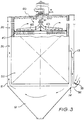
- the fabric filter apparatus 10 comprises a housing 11 having at its lower end an inwardly tapering hopper 12.
- the housing 11 is divided into upper clean gas zone 20 and lower dusty gas zone 30.
- a porting plate 40 is provided therebetween from which a circular array of filter bags 50 depend. Please note that the relative sizes of the various components are not to scale.
- the porting plate 40 has a series of radially spaced concentric ring of ports. Each of these ports communicates with a respective filter bag of the circular filter bag array 50. Above the porting plate is a gas pulse generation/distribution system 60 (see Fig. 3) substantially as disclosed in Australian Patent No 608765.
- the gas pulse generation/distribution system 60 includes a vertically extending inlet tube 61 which is connected at its lower end to a pair of radially extending gas manifolds 62 and 63.
- Each manifold 62 and 63 extends across and above the porting plate 40 and carries a plurality of downwardly directed nozzles.
- the nozzles of manifold 62 are positioned so that they respectively rotate over one of the even numbered rings of ports while the nozzles of manifold 63 are positioned so that they respectively rotate over one of the odd numbered rings of ports.
- the generation/distribution system 60 can be produced in alternative manners as a matter of design preference.
- the nozzles of each manifold 62 and 62 can be arranged as a plurality of equally radially spaced pairs, each nozzle 25 of a respective pair aligning upon rotation with its respective ring of ports.
- a dusty gas inlet 31 extends across one face of the housing 11 and opens preferably into hopper 12. As more clearly shown in Fig. 3, this inlet comprises an inlet hopper 32 and damper 33 disposed in the inlet hopper and adapted to control the volume of the gas flowing through the inlet hopper 31 into housing 11.
- the damper is provided by a rotatable vane however any suitable air damper means may be used.
- the housing 11 includes at least one duct 13 the bottom of which is in fluid communication with inlet 31.
- the top of the duct 13 opens into the housing 11 at a position intermediate the inlet 31 and the porting plate 40.
- two ducts 13 extend substantially vertically in adjacent corners of the housing, the bottoms of these ducts being in fluid communication with the opposite lateral ends of inlet 31.
- the inventive apparatus operates as follows. A vacuum is provided in the clean gas section 20 so that a first portion of the dusty gas is drawn through inlet 31 and into the housing 11 at a position adjacent or below the circular filter bag array 50.
- Ducts 13 in housing 11 divert a second portion of the dusty gas entering the housing from the inlet 31 and deliver it to a corner of the housing at a level intermediate the porting plate 40 and inlet 32.
- the ducts may be sized according to the amount of inlet flow to be diverted. Between 10% - 90% of the total dusty gas entering the filter may be diverted to a corner of the housing at a level intermediate the porting plate and the inlet.
- the dusty gas in the housing is then drawn through the circular filter bag array 50 with the particulate matter in the dusty gas being separated by the filter bags.
- the clean air then passes through the open upper end of the filter bags into the clean air section 20 where it is removed via outlet 21.
- each inlet duct is provided with a small bleed aperture 14 at its lower end so that any particulate matter that may drop out of he dusty gas stream in duct 13 may be discharged from its lower end and directed into hopper 12.
Landscapes
- Chemical & Material Sciences (AREA)
- Chemical Kinetics & Catalysis (AREA)
- Filtering Of Dispersed Particles In Gases (AREA)
- Filtering Materials (AREA)
- Treatment Of Fiber Materials (AREA)
- Air Bags (AREA)
- Pipeline Systems (AREA)
- Auxiliary Devices For And Details Of Packaging Control (AREA)
- Dry Shavers And Clippers (AREA)
- Devices For Conveying Motion By Means Of Endless Flexible Members (AREA)
- Seats For Vehicles (AREA)
- Spinning Or Twisting Of Yarns (AREA)
Claims (8)
- Gewebefiltervorrichtung (10) mit einem prismatischen Gehäuse (11), das einen Staubgasabschnitt (30) mit einem daran befindlichen, länglichen, horizontalen Einlaß (31) und einen Reingasabschnitt (20) mit einem Auslaß (21) von diesem weg, begrenzt, einer in dem Gehäuse montierten Tragplatte (40), welche den Staubgasabschnitt von dem Reingasabschnitt trennt und einem im wesentlichen kreisförmigen Bereich bzw. einer Reihe von Gewebefiltertüten (50), der/die daran herunterhängt, wobei der Einlaß an dem untersten Ende der Filtertüten angrenzt, wobei das Gehäuse desweiteren eine Erzeugungs-/Verteilungseinrichtung (60) umfaßt zur Erzeugung von Impulsen bzw. Stößen an rückgespülten Gas und zur periodischen Verteilung der Impulse bzw. Stöße in die oberen Enden der Gewebefiltertüten durch entsprechende Öffnungen in der Tragplatte, wobei entsprechende Staubgasdurchflußkanäle (13) an den beiden Ecken des prismatischen Gehäuses angeordnet sind, die den seitlichen Enden des Einlasses gegenüberliegen, wobei die Kanäle in fluidmäßiger Verbindung stehen mit dem Einlaß (31) und sich im wesentlichen vertikal nach oben erstrecken, um einen Teil des Staubgases, der durch den Einlaß einströmt in dem Gehäuse nach oben zu richten, damit dieser jeden Kanal (13) auf einem Niveau zwischen dem Einlaß (31) und der Tragplatte (40) verläßt.
- Gewebefiltervorrichtung nach Anspruch 1, wobei das Gehäuse vier planare Seiten aufweist und mit zwei im wesentlichen vertikal orientierten Kanälen versehen ist, wobei der Einlaß sich entlang einer Seite des Gehäuses erstreckt und beide Kanäle in aneinander angrenzenden Ecken des Gehäuses angeordnet sind.
- Gewebefiltervorrichtung nach einem der vorstehenden Ansprüche, wobei das untere Ende des Gehäuses durch einen sich nach unten verjüngenden Trichter (12) gebildet ist und der Einlaß sich in den Trichter öffnet.
- Gewebefiltervorrichtung nach einem der vorstehenden Ansprüche, wobei ein Dämpfer (33) in dem Einlaß montiert ist um die Gasströmung bzw. den Gasfluß in das Gehäuse zu steuern.
- Gewebefiltervorrichtung nach einem der vorstehenden Ansprüche, wobei jeder Kanal (13) an seinem unteren Abschnitt mit einer Ablaß- bzw. Abzapföffnung (14) versehen ist, die es aus dem Staubgas ausgefällten Teilchenmaterial erlaubt, in jedem entsprechenden Kanal zu entweichen bzw. auszuscheiden.
- Verfahren zum Zuführen eines Staubgases zu einem Staubgasabschnitt (30) eines Gewebefilters (10) innerhalb eines prismatischen Gehäuses, wobei das Filter desweiteren umfaßt: einen Reingasabschnitt (20), eine Tragplatte (40), die zwischen dem Staubgasabschnitt und dem Reingasabschnitt montiert ist, mit einem kreisförmigen Bereich bzw. einer Reihe von Gewebefiltertüten (50), die von der Tragplatte herabhängen und einer Erzeugungs-/Verteilungseinrichtung (60) zum Erzeugen von Impulsen bzw. Stößen aus rückgeführtem Gas und zur periodischen Verteilung der Impulse bzw. Stöße in die offenen oberen Enden der Gewebefiltertüten durch entsprechende Öffnungen in der Tragplatte, wobei ein erster Teil des Staubgases direkt in das Gehäuse zugeführt wird an einer Position unterhalb oder am Boden des Filtertütenbereichs angrenzend und ein zweiter Teil des Staubgases von einem Staubgaseinlaß (31) zu dem Gehäuse ab bzw. umgelenkt und auf ein Niveau befördert wird zwischen dem Einlaß und der Tragplatte, und zwar über zwei voneinander beabstandete Kanäle (13), die an gegenüberliegenden, seitlichen Enden des Staubgaseinlasses ausgebildet sind, wobei die beiden Kanäle sich im wesentlichen vertikal nach oben in zwei Ecken des Gehäuses erstrecken.
- Verfahren zum Zuführen eines Staubgases zu einem Staubgasabschnitt eines Gewebefilters nach Anspruch 6, wobei der Einlaß vorgesehen ist durch eine längliche Öffnung (32), die sich entlang einer Seite des Gehäuses erstreckt, wobei das Staubgas an gegenüberliegenden seitlichen Endabschnitten der Einlaßöffnung vertikal nach oben ab- bzw. umgelenkt wird.
- Verfahren zum Zuführen eines Staubgases zu einem Staubgasabschnitt eines Gewebefilters nach einem der Ansprüche 6 oder 7, wobei der zweite Teil zwischen 10% und 90% des gesamten, in das Filter eintretenden Staubgasstromes ausmacht.
Applications Claiming Priority (3)
| Application Number | Priority Date | Filing Date | Title |
|---|---|---|---|
| AUPM3290/94 | 1994-01-10 | ||
| AUPM3290A AUPM329094A0 (en) | 1994-01-10 | 1994-01-10 | Fabric filter |
| PCT/AU1994/000738 WO1995018662A1 (en) | 1994-01-10 | 1994-12-01 | Fabric filter |
Publications (3)
| Publication Number | Publication Date |
|---|---|
| EP0739230A1 EP0739230A1 (de) | 1996-10-30 |
| EP0739230A4 EP0739230A4 (de) | 1997-05-14 |
| EP0739230B1 true EP0739230B1 (de) | 1999-05-12 |
Family
ID=3777913
Family Applications (1)
| Application Number | Title | Priority Date | Filing Date |
|---|---|---|---|
| EP95902001A Expired - Lifetime EP0739230B1 (de) | 1994-01-10 | 1994-12-01 | Gewebefilter |
Country Status (22)
| Country | Link |
|---|---|
| US (1) | US5846300A (de) |
| EP (1) | EP0739230B1 (de) |
| JP (1) | JP3334053B2 (de) |
| KR (1) | KR100360638B1 (de) |
| CN (1) | CN1143331A (de) |
| AT (1) | ATE179903T1 (de) |
| AU (2) | AUPM329094A0 (de) |
| BR (1) | BR9408489A (de) |
| CA (1) | CA2180436C (de) |
| CZ (1) | CZ203196A3 (de) |
| DE (1) | DE69418486T2 (de) |
| ES (1) | ES2131793T3 (de) |
| HU (1) | HUT76176A (de) |
| IN (1) | IN189545B (de) |
| NO (1) | NO310063B1 (de) |
| NZ (1) | NZ276668A (de) |
| PL (1) | PL176575B1 (de) |
| RO (1) | RO119926B1 (de) |
| SG (1) | SG46240A1 (de) |
| SK (1) | SK88896A3 (de) |
| WO (1) | WO1995018662A1 (de) |
| ZA (1) | ZA9578B (de) |
Families Citing this family (13)
| Publication number | Priority date | Publication date | Assignee | Title |
|---|---|---|---|---|
| US6036751A (en) * | 1998-08-04 | 2000-03-14 | Ribardi; Harris J. | System for depressurizing, filtering, and noise suppression of high pressure pneumatic vessels |
| US6146433A (en) * | 1999-05-11 | 2000-11-14 | Venturedyne, Ltd. | Internal air baffle |
| RU2190455C2 (ru) * | 2000-08-10 | 2002-10-10 | Богданов Виктор Григорьевич | Устройство для очистки газа от пыли |
| DK175107B1 (da) * | 2003-02-12 | 2004-06-01 | Simatek As | Filter med indlöbsdel med diffuserelementer |
| US9254458B2 (en) | 2006-08-21 | 2016-02-09 | Simatek A/S | Filter inlet |
| KR100894313B1 (ko) | 2007-07-06 | 2009-04-24 | 주식회사 신성플랜트 | 집진장치 |
| CA2771877A1 (en) * | 2009-09-09 | 2011-03-17 | Strauss Water Ltd | Liquid filter device |
| DE102010045000A1 (de) * | 2010-09-10 | 2012-03-15 | Herding Gmbh Filtertechnik | Filtervorrichtung und Filterverfahren |
| CN102313716A (zh) * | 2011-07-26 | 2012-01-11 | 武汉米字科技有限公司 | 一种基于可调谐激光吸收技术的痕量气体分析系统 |
| EP3274066B1 (de) | 2015-03-23 | 2020-04-22 | Strauss Water Ltd | Wasserfilter und anordnung daraus |
| CN106669301B (zh) * | 2016-09-13 | 2022-06-07 | 沈阳隆基电磁科技股份有限公司 | 一种用于单晶生长炉的真空除尘设备 |
| CN106621602A (zh) * | 2016-12-27 | 2017-05-10 | 明辉大秦(上海)环保科技股份有限公司 | 一种高性能环保型速溶胶粉的粉尘过滤回收系统 |
| CN113731954B (zh) * | 2021-11-08 | 2023-08-01 | 宁波市北仑旭阳模塑制造有限公司 | 一种吹绒柜 |
Family Cites Families (14)
| Publication number | Priority date | Publication date | Assignee | Title |
|---|---|---|---|---|
| US1743934A (en) * | 1924-11-26 | 1930-01-14 | Ruemelin Richard | Dust separator |
| DE1410811B1 (de) * | 1961-10-27 | 1970-11-12 | Boewe Boehler & Weber Kg Masch | Verfahren und Vorrichtung zum Reinigen von in einer Chemisch-Reinigungsmaschine anfallendem,schmutzversetztem Loesungsmittel |
| US3726066A (en) * | 1970-12-14 | 1973-04-10 | Wheelabrator Frye Inc | Dust collector |
| US4157899A (en) * | 1977-10-11 | 1979-06-12 | Cea Carter-Day Company | Pulsed backflush air filter |
| US4521231A (en) * | 1983-11-10 | 1985-06-04 | General Electric Environmental Services, Inc. | High capacity gas filter system |
| CN1010377B (zh) * | 1986-07-11 | 1990-11-14 | 豪登环境系统公司 | 脉冲喷气织网过滤器 |
| DE3639824A1 (de) * | 1986-10-22 | 1988-05-05 | Margraf Adolf | Filternder abscheider fuer partikel und schadgase aus rohgasen |
| US4764190A (en) * | 1987-02-10 | 1988-08-16 | Westinghouse Electric Corp. | High temperature, high pressure gas filter system |
| US4872981A (en) * | 1988-01-07 | 1989-10-10 | Hobson Jr Russell | Split inlet for filter |
| US4883509A (en) * | 1988-02-12 | 1989-11-28 | Giambattista Giusti | Multi stage gas inlet construction for dust collectors |
| DE3930765C1 (en) * | 1989-09-14 | 1991-02-28 | Metallgesellschaft Ag, 6000 Frankfurt, De | Tubular gas filter - has several chambers contg. filter elements in housing, with dust collection bunker under each chamber |
| FI87540C (fi) * | 1989-12-22 | 1993-01-25 | Tampella Oy Ab | Foerfarande och anordning foer matning av gas till partikelfilter |
| US5387406A (en) * | 1990-09-17 | 1995-02-07 | Walther & Cie Ag | Method and device for the adsorption and chemisorption, respectively, of gaseous components in a gas stream |
| DE4212769A1 (de) * | 1992-04-16 | 1993-10-21 | Schumacher Umwelt Trenntech | Vorrichtung zur gleichmäßigen Verteilung einer Zweiphasenströmung |
-
1994
- 1994-01-10 AU AUPM3290A patent/AUPM329094A0/en not_active Abandoned
- 1994-12-01 JP JP51822195A patent/JP3334053B2/ja not_active Expired - Fee Related
- 1994-12-01 CN CN94195050A patent/CN1143331A/zh active Pending
- 1994-12-01 US US08/669,468 patent/US5846300A/en not_active Expired - Fee Related
- 1994-12-01 HU HU9601863A patent/HUT76176A/hu unknown
- 1994-12-01 WO PCT/AU1994/000738 patent/WO1995018662A1/en not_active Ceased
- 1994-12-01 EP EP95902001A patent/EP0739230B1/de not_active Expired - Lifetime
- 1994-12-01 PL PL94315581A patent/PL176575B1/pl not_active IP Right Cessation
- 1994-12-01 SK SK888-96A patent/SK88896A3/sk unknown
- 1994-12-01 AT AT95902001T patent/ATE179903T1/de active
- 1994-12-01 RO RO96-01410A patent/RO119926B1/ro unknown
- 1994-12-01 ES ES95902001T patent/ES2131793T3/es not_active Expired - Lifetime
- 1994-12-01 BR BR9408489A patent/BR9408489A/pt not_active Application Discontinuation
- 1994-12-01 DE DE69418486T patent/DE69418486T2/de not_active Expired - Lifetime
- 1994-12-01 SG SG1996001468A patent/SG46240A1/en unknown
- 1994-12-01 KR KR1019960703707A patent/KR100360638B1/ko not_active Expired - Fee Related
- 1994-12-01 NZ NZ276668A patent/NZ276668A/en not_active IP Right Cessation
- 1994-12-01 CA CA002180436A patent/CA2180436C/en not_active Expired - Lifetime
- 1994-12-01 AU AU11033/95A patent/AU691851B2/en not_active Ceased
- 1994-12-01 CZ CZ962031A patent/CZ203196A3/cs unknown
- 1994-12-29 IN IN1709DE1994 patent/IN189545B/en unknown
-
1995
- 1995-01-06 ZA ZA9578A patent/ZA9578B/xx unknown
-
1996
- 1996-07-09 NO NO962888A patent/NO310063B1/no not_active IP Right Cessation
Also Published As
| Publication number | Publication date |
|---|---|
| CZ203196A3 (en) | 1996-12-11 |
| JPH09508307A (ja) | 1997-08-26 |
| ATE179903T1 (de) | 1999-05-15 |
| PL315581A1 (en) | 1996-11-12 |
| NZ276668A (en) | 1997-04-24 |
| AU1103395A (en) | 1995-08-01 |
| KR100360638B1 (ko) | 2003-01-29 |
| IN189545B (de) | 2003-03-22 |
| EP0739230A4 (de) | 1997-05-14 |
| EP0739230A1 (de) | 1996-10-30 |
| RO119926B1 (ro) | 2005-06-30 |
| ZA9578B (en) | 1995-09-06 |
| SG46240A1 (en) | 1998-02-20 |
| BR9408489A (pt) | 1997-08-26 |
| WO1995018662A1 (en) | 1995-07-13 |
| NO962888L (no) | 1996-07-09 |
| NO962888D0 (no) | 1996-07-09 |
| CN1143331A (zh) | 1997-02-19 |
| PL176575B1 (pl) | 1999-06-30 |
| AUPM329094A0 (en) | 1994-02-03 |
| DE69418486T2 (de) | 1999-09-09 |
| HUT76176A (en) | 1997-07-28 |
| US5846300A (en) | 1998-12-08 |
| JP3334053B2 (ja) | 2002-10-15 |
| CA2180436C (en) | 2004-06-22 |
| HU9601863D0 (en) | 1996-09-30 |
| CA2180436A1 (en) | 1995-07-13 |
| SK88896A3 (en) | 1997-09-10 |
| NO310063B1 (no) | 2001-05-14 |
| AU691851B2 (en) | 1998-05-28 |
| ES2131793T3 (es) | 1999-08-01 |
| DE69418486D1 (de) | 1999-06-17 |
Similar Documents
| Publication | Publication Date | Title |
|---|---|---|
| EP0739230B1 (de) | Gewebefilter | |
| EP0172538B1 (de) | Flächenfilter mit Staubsammler für abwärts gerichtete Strömung | |
| US4655804A (en) | Hopper gas distribution system | |
| US4354451A (en) | Device for spray-coating a workpiece with powder particles | |
| EP0391969B1 (de) | Selbstreinigende siebanorndung | |
| US4359330A (en) | Self-cleaning pulsed air cleaner with integral precleaner | |
| US8460443B2 (en) | Portable dust collector | |
| US20140360371A1 (en) | Portable Dust Collector | |
| JP6050101B2 (ja) | 集塵装置 | |
| CA2167089C (en) | An apparatus for and a method of filtering gases | |
| EP0083169B1 (de) | Filtrationsapparat mit einem zweiten Gasauslasssystem | |
| US4610704A (en) | Downflow dust filter | |
| US4227900A (en) | Apparatus for filtering gas streams | |
| EP0223873B1 (de) | Staubabscheider | |
| JP2746785B2 (ja) | バグフィルタの洗浄方法 | |
| JP6276831B2 (ja) | 集塵装置 | |
| CA1277251C (en) | Dust separator | |
| SU1286302A1 (ru) | Устройство дл очистки зерна | |
| SU889756A1 (ru) | Аэродинамический отделитель дл волокнистого материала | |
| RU96117264A (ru) | Тканевый фильтр | |
| JPH0638889B2 (ja) | ガスフイルタ装置 |
Legal Events
| Date | Code | Title | Description |
|---|---|---|---|
| PUAI | Public reference made under article 153(3) epc to a published international application that has entered the european phase |
Free format text: ORIGINAL CODE: 0009012 |
|
| 17P | Request for examination filed |
Effective date: 19960801 |
|
| AK | Designated contracting states |
Kind code of ref document: A1 Designated state(s): AT BE CH DE DK ES FR GB GR IE IT LI LU MC NL PT SE |
|
| A4 | Supplementary search report drawn up and despatched |
Effective date: 19970401 |
|
| AK | Designated contracting states |
Kind code of ref document: A4 Designated state(s): AT BE CH DE DK ES FR GB GR IE IT LI LU MC NL PT SE |
|
| 17Q | First examination report despatched |
Effective date: 19980112 |
|
| GRAG | Despatch of communication of intention to grant |
Free format text: ORIGINAL CODE: EPIDOS AGRA |
|
| GRAG | Despatch of communication of intention to grant |
Free format text: ORIGINAL CODE: EPIDOS AGRA |
|
| GRAH | Despatch of communication of intention to grant a patent |
Free format text: ORIGINAL CODE: EPIDOS IGRA |
|
| GRAH | Despatch of communication of intention to grant a patent |
Free format text: ORIGINAL CODE: EPIDOS IGRA |
|
| GRAA | (expected) grant |
Free format text: ORIGINAL CODE: 0009210 |
|
| AK | Designated contracting states |
Kind code of ref document: B1 Designated state(s): AT BE CH DE DK ES FR GB GR IE IT LI LU MC NL PT SE |
|
| PG25 | Lapsed in a contracting state [announced via postgrant information from national office to epo] |
Ref country code: SE Free format text: THE PATENT HAS BEEN ANNULLED BY A DECISION OF A NATIONAL AUTHORITY Effective date: 19990512 Ref country code: NL Free format text: LAPSE BECAUSE OF FAILURE TO SUBMIT A TRANSLATION OF THE DESCRIPTION OR TO PAY THE FEE WITHIN THE PRESCRIBED TIME-LIMIT Effective date: 19990512 Ref country code: GR Free format text: LAPSE BECAUSE OF NON-PAYMENT OF DUE FEES Effective date: 19990512 Ref country code: BE Free format text: LAPSE BECAUSE OF FAILURE TO SUBMIT A TRANSLATION OF THE DESCRIPTION OR TO PAY THE FEE WITHIN THE PRESCRIBED TIME-LIMIT Effective date: 19990512 |
|
| REF | Corresponds to: |
Ref document number: 179903 Country of ref document: AT Date of ref document: 19990515 Kind code of ref document: T |
|
| REG | Reference to a national code |
Ref country code: CH Ref legal event code: EP |
|
| ET | Fr: translation filed | ||
| REG | Reference to a national code |
Ref country code: CH Ref legal event code: NV Representative=s name: CABINET ROLAND NITHARDT CONSEILS EN PROPRIETE INDU |
|
| REG | Reference to a national code |
Ref country code: IE Ref legal event code: FG4D |
|
| REF | Corresponds to: |
Ref document number: 69418486 Country of ref document: DE Date of ref document: 19990617 |
|
| REG | Reference to a national code |
Ref country code: ES Ref legal event code: FG2A Ref document number: 2131793 Country of ref document: ES Kind code of ref document: T3 |
|
| PG25 | Lapsed in a contracting state [announced via postgrant information from national office to epo] |
Ref country code: PT Free format text: LAPSE BECAUSE OF FAILURE TO SUBMIT A TRANSLATION OF THE DESCRIPTION OR TO PAY THE FEE WITHIN THE PRESCRIBED TIME-LIMIT Effective date: 19990812 Ref country code: DK Free format text: LAPSE BECAUSE OF FAILURE TO SUBMIT A TRANSLATION OF THE DESCRIPTION OR TO PAY THE FEE WITHIN THE PRESCRIBED TIME-LIMIT Effective date: 19990812 |
|
| PG25 | Lapsed in a contracting state [announced via postgrant information from national office to epo] |
Ref country code: LU Free format text: LAPSE BECAUSE OF NON-PAYMENT OF DUE FEES Effective date: 19991201 Ref country code: IE Free format text: LAPSE BECAUSE OF NON-PAYMENT OF DUE FEES Effective date: 19991201 |
|
| PLBE | No opposition filed within time limit |
Free format text: ORIGINAL CODE: 0009261 |
|
| STAA | Information on the status of an ep patent application or granted ep patent |
Free format text: STATUS: NO OPPOSITION FILED WITHIN TIME LIMIT |
|
| 26N | No opposition filed | ||
| PG25 | Lapsed in a contracting state [announced via postgrant information from national office to epo] |
Ref country code: MC Free format text: LAPSE BECAUSE OF NON-PAYMENT OF DUE FEES Effective date: 20000630 |
|
| REG | Reference to a national code |
Ref country code: IE Ref legal event code: MM4A |
|
| REG | Reference to a national code |
Ref country code: GB Ref legal event code: IF02 |
|
| REG | Reference to a national code |
Ref country code: CH Ref legal event code: PFA Free format text: LURGI (AUSTRALIA) PTY LIMITED TRANSFER- LURGI PACIFIC PTY LTD |
|
| REG | Reference to a national code |
Ref country code: CH Ref legal event code: PFA Free format text: LURGI PACIFIC PTY LTD,230 ALBERT ROAD,SOUTH MELBOURNE, VIC 3205 (AU) TRANSFER- LURGI PACIFIC PTY LTD,72 MARKET STREET,SOUTH MELBOURNE, VICTORIA 3205 (AU) |
|
| REG | Reference to a national code |
Ref country code: FR Ref legal event code: CD Ref country code: FR Ref legal event code: CA |
|
| REG | Reference to a national code |
Ref country code: ES Ref legal event code: PC2A |
|
| REG | Reference to a national code |
Ref country code: CH Ref legal event code: PCAR Free format text: CABINET ROLAND NITHARDT CONSEILS EN PROPRIETE INDUSTRIELLE S.A.;Y-PARC RUE GALILEE;1400 YVERDON-LES-BAINS (CH) |
|
| PGFP | Annual fee paid to national office [announced via postgrant information from national office to epo] |
Ref country code: CH Payment date: 20121221 Year of fee payment: 19 |
|
| PGFP | Annual fee paid to national office [announced via postgrant information from national office to epo] |
Ref country code: GB Payment date: 20121220 Year of fee payment: 19 Ref country code: IT Payment date: 20121227 Year of fee payment: 19 |
|
| PGFP | Annual fee paid to national office [announced via postgrant information from national office to epo] |
Ref country code: AT Payment date: 20121212 Year of fee payment: 19 |
|
| PGFP | Annual fee paid to national office [announced via postgrant information from national office to epo] |
Ref country code: DE Payment date: 20130225 Year of fee payment: 19 Ref country code: FR Payment date: 20130130 Year of fee payment: 19 Ref country code: ES Payment date: 20121226 Year of fee payment: 19 |
|
| REG | Reference to a national code |
Ref country code: DE Ref legal event code: R119 Ref document number: 69418486 Country of ref document: DE |
|
| REG | Reference to a national code |
Ref country code: CH Ref legal event code: PL |
|
| REG | Reference to a national code |
Ref country code: AT Ref legal event code: MM01 Ref document number: 179903 Country of ref document: AT Kind code of ref document: T Effective date: 20131201 |
|
| GBPC | Gb: european patent ceased through non-payment of renewal fee |
Effective date: 20131201 |
|
| REG | Reference to a national code |
Ref country code: DE Ref legal event code: R119 Ref document number: 69418486 Country of ref document: DE Effective date: 20140701 |
|
| REG | Reference to a national code |
Ref country code: FR Ref legal event code: ST Effective date: 20140829 |
|
| PG25 | Lapsed in a contracting state [announced via postgrant information from national office to epo] |
Ref country code: CH Free format text: LAPSE BECAUSE OF NON-PAYMENT OF DUE FEES Effective date: 20131231 Ref country code: DE Free format text: LAPSE BECAUSE OF NON-PAYMENT OF DUE FEES Effective date: 20140701 Ref country code: LI Free format text: LAPSE BECAUSE OF NON-PAYMENT OF DUE FEES Effective date: 20131231 |
|
| PG25 | Lapsed in a contracting state [announced via postgrant information from national office to epo] |
Ref country code: GB Free format text: LAPSE BECAUSE OF NON-PAYMENT OF DUE FEES Effective date: 20131201 Ref country code: AT Free format text: LAPSE BECAUSE OF NON-PAYMENT OF DUE FEES Effective date: 20131201 Ref country code: FR Free format text: LAPSE BECAUSE OF NON-PAYMENT OF DUE FEES Effective date: 20131231 |
|
| REG | Reference to a national code |
Ref country code: ES Ref legal event code: FD2A Effective date: 20150330 |
|
| PG25 | Lapsed in a contracting state [announced via postgrant information from national office to epo] |
Ref country code: ES Free format text: LAPSE BECAUSE OF NON-PAYMENT OF DUE FEES Effective date: 20131202 |
|
| PG25 | Lapsed in a contracting state [announced via postgrant information from national office to epo] |
Ref country code: IT Free format text: LAPSE BECAUSE OF NON-PAYMENT OF DUE FEES Effective date: 20131201 |