EP0739672A2 - Dispositif de serrage à serrer des pièces à travailler avec une surface non-réguliere - Google Patents
Dispositif de serrage à serrer des pièces à travailler avec une surface non-réguliere Download PDFInfo
- Publication number
- EP0739672A2 EP0739672A2 EP96104857A EP96104857A EP0739672A2 EP 0739672 A2 EP0739672 A2 EP 0739672A2 EP 96104857 A EP96104857 A EP 96104857A EP 96104857 A EP96104857 A EP 96104857A EP 0739672 A2 EP0739672 A2 EP 0739672A2
- Authority
- EP
- European Patent Office
- Prior art keywords
- base body
- clamping
- clamping device
- holding device
- section
- Prior art date
- Legal status (The legal status is an assumption and is not a legal conclusion. Google has not performed a legal analysis and makes no representation as to the accuracy of the status listed.)
- Granted
Links
Images
Classifications
-
- B—PERFORMING OPERATIONS; TRANSPORTING
- B23—MACHINE TOOLS; METAL-WORKING NOT OTHERWISE PROVIDED FOR
- B23B—TURNING; BORING
- B23B31/00—Chucks; Expansion mandrels; Adaptations thereof for remote control
- B23B31/02—Chucks
- B23B31/10—Chucks characterised by the retaining or gripping devices or their immediate operating means
- B23B31/12—Chucks with simultaneously-acting jaws, whether or not also individually adjustable
- B23B31/16—Chucks with simultaneously-acting jaws, whether or not also individually adjustable moving radially
- B23B31/1627—Details of the jaws
- B23B31/16275—Form of the jaws
-
- B—PERFORMING OPERATIONS; TRANSPORTING
- B23—MACHINE TOOLS; METAL-WORKING NOT OTHERWISE PROVIDED FOR
- B23B—TURNING; BORING
- B23B31/00—Chucks; Expansion mandrels; Adaptations thereof for remote control
- B23B31/02—Chucks
- B23B31/10—Chucks characterised by the retaining or gripping devices or their immediate operating means
- B23B31/12—Chucks with simultaneously-acting jaws, whether or not also individually adjustable
- B23B31/16—Chucks with simultaneously-acting jaws, whether or not also individually adjustable moving radially
- B23B31/16287—Chucks with simultaneously-acting jaws, whether or not also individually adjustable moving radially using fluid-pressure means to actuate the gripping means
-
- B—PERFORMING OPERATIONS; TRANSPORTING
- B23—MACHINE TOOLS; METAL-WORKING NOT OTHERWISE PROVIDED FOR
- B23Q—DETAILS, COMPONENTS, OR ACCESSORIES FOR MACHINE TOOLS, e.g. ARRANGEMENTS FOR COPYING OR CONTROLLING; MACHINE TOOLS IN GENERAL CHARACTERISED BY THE CONSTRUCTION OF PARTICULAR DETAILS OR COMPONENTS; COMBINATIONS OR ASSOCIATIONS OF METAL-WORKING MACHINES, NOT DIRECTED TO A PARTICULAR RESULT
- B23Q1/00—Members which are comprised in the general build-up of a form of machine, particularly relatively large fixed members
- B23Q1/25—Movable or adjustable work or tool supports
- B23Q1/44—Movable or adjustable work or tool supports using particular mechanisms
- B23Q1/50—Movable or adjustable work or tool supports using particular mechanisms with rotating pairs only, the rotating pairs being the first two elements of the mechanism
- B23Q1/52—Movable or adjustable work or tool supports using particular mechanisms with rotating pairs only, the rotating pairs being the first two elements of the mechanism a single rotating pair
- B23Q1/527—Movable or adjustable work or tool supports using particular mechanisms with rotating pairs only, the rotating pairs being the first two elements of the mechanism a single rotating pair with a ring or tube in which a workpiece is fixed coaxially to the degree of freedom
-
- B—PERFORMING OPERATIONS; TRANSPORTING
- B23—MACHINE TOOLS; METAL-WORKING NOT OTHERWISE PROVIDED FOR
- B23Q—DETAILS, COMPONENTS, OR ACCESSORIES FOR MACHINE TOOLS, e.g. ARRANGEMENTS FOR COPYING OR CONTROLLING; MACHINE TOOLS IN GENERAL CHARACTERISED BY THE CONSTRUCTION OF PARTICULAR DETAILS OR COMPONENTS; COMBINATIONS OR ASSOCIATIONS OF METAL-WORKING MACHINES, NOT DIRECTED TO A PARTICULAR RESULT
- B23Q3/00—Devices holding, supporting, or positioning work or tools, of a kind normally removable from the machine
- B23Q3/02—Devices holding, supporting, or positioning work or tools, of a kind normally removable from the machine for mounting on a work-table, tool-slide, or analogous part
- B23Q3/06—Work-clamping means
- B23Q3/062—Work-clamping means adapted for holding workpieces having a special form or being made from a special material
- B23Q3/063—Work-clamping means adapted for holding workpieces having a special form or being made from a special material for holding turbine blades
-
- B—PERFORMING OPERATIONS; TRANSPORTING
- B25—HAND TOOLS; PORTABLE POWER-DRIVEN TOOLS; MANIPULATORS
- B25B—TOOLS OR BENCH DEVICES NOT OTHERWISE PROVIDED FOR, FOR FASTENING, CONNECTING, DISENGAGING, OR HOLDING
- B25B1/00—Vices
- B25B1/24—Details, e.g. jaws of special shape, slideways
- B25B1/2405—Construction of the jaws
- B25B1/241—Construction of the jaws characterised by surface features or material
- B25B1/2415—Construction of the jaws characterised by surface features or material being composed of a plurality of parts adapting to the shape of the workpiece
- B25B1/2421—Construction of the jaws characterised by surface features or material being composed of a plurality of parts adapting to the shape of the workpiece the parts having a linear movement
Definitions
- the invention relates to a clamping device for the circumferential clamping of workpieces with any circumferential contour, with two mold clamping jaws arranged opposite one another on a base body, the clamping surfaces of which are each formed by a plurality of plungers which can be moved fluidically against the workpiece to be clamped and locked in the clamping position.
- Such a clamping device known from DE 42 02 032 is used for clamping workpieces with any circumferential contour, for example also on drilling and milling machines, the workpieces being clamped and released quickly and easily.
- a particular problem is, for example, the production of turbine blades or similar molded parts, in which both a central area with a complicated circumferential contour and anchoring elements on both sides have to be produced.
- the workpiece When machining, the workpiece must be rotated exactly about a defined longitudinal axis and locked in different angular positions, which with the known clamping device is not easily possible.
- the base body is rotatably mounted in a holding device about an axis directed perpendicular to the clamping direction and has a connecting piece for fluidic control of the fluidic drive at least the plunger, and that a mating connector connected with fluidic lines is displaceable against the connecting piece and can be coupled to the base body in a certain angular position when the base body is not in motion, the base body having valve means for fixing the positions of the tappets in the tensioned state after uncoupling the counter-connection piece.
- the known clamping device can advantageously be moved to a rotatably clamped workpiece in such a way that its axis of rotation coincides with the axis of rotation of the base body.
- the plungers of the mold clamping jaws are actuated, so that they clamp an area of the workpiece with a complicated peripheral contour, for example the blade contour of a turbine blade.
- the plungers After uncoupling the counter connector the plungers remain in the clamped state, so that the base body can again be freely rotated and forms an additional rotary bearing for the workpiece to be machined.
- the base body is designed in the form of a circular disk and is mounted on the circumference, the circumferential mounting in the base body preferably containing a multiplicity of roller bearings which can rest on the circumference surface of the base body.
- a drive motor is expediently provided for rotating the base body, the drive motor fixed to the holding device in particular via at least one drive gearwheel engages in a circumferential or in the circumferential area arranged ring gear on the base body. This enables exact angular positioning of the base body and thus the clamped workpiece.
- the base body expediently has a continuous opening which laterally delimits the axially continuous clamping jaws laterally from the two mold clamping jaws and which also extends through the holding device.
- the pre-clamped workpiece can pass through the recess to the clamping opening between the mold clamping jaws in order to then be clamped.
- the base body thus also has an interruption in the ring gear, two drive gearwheels are advantageously provided, the spacing of which corresponds at least to the width of the recess, so that a continuous drive is ensured.
- the base body and the holding device are each formed in two parts, the parts being designed to be pivotable apart for the insertion and removal of the workpiece to be clamped.
- the holding device expediently consists of a first section guided on a guide device and a second section which is pivotally connected to the first section via a swivel joint, wherein during the pivoting process a first section of the base body remains in the first section of the holding device and a second section of the base body is also pivoted in the second section of the holding device.
- the two sections of the base body together form a closed circular disc that can be easily supported and driven by a single drive wheel.
- the holding device preferably has an actuator which can be actuated in particular in a fluidic manner.
- a locking device which locks the two sections of the holding device in the closed state and which is preferably operated or controlled fluidically.
- the mating connector is preferably designed to be fluidly displaceable for coupling to the connector. This enables quick coupling and uncoupling.
- the two mold clamping jaws are advantageous arranged on slides which can be fluidically displaced relative to one another on the base body.
- An even greater variability is achieved in that the mold clamping jaws can be fluidly coupled to the slide and / or locked, so that different mold clamping jaws which can alternatively be fixed on the slide can be provided and can be removed, for example, from a magazine.
- At least one fluidic parking brake which is designed in particular as a shoe brake on the outer circumference of the base body, is suitable for the fixed positioning of the base body in different angular positions.
- the holding device To position the holding device relative to the pre-clamped tool, it expediently has a drive device for axial and / or horizontal displacement on a guide device transversely to the axial direction.
- the means for fixing the plunger in the tensioned state are preferably designed as fluidically operable shut-off valves, preferably non-return valves are provided for maintaining the plunger positions after the counter-connector has been uncoupled.
- each mold clamping jaw extends over the plunger Has tension band, which rests preferably by spring force on the tappets.
- a hydraulic control is preferably suitable as the fluidic control.
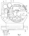
- the tensioning device shown in FIGS. 1 and 2 essentially consists of a holding device 10 in which a circular disk-like base body 11 is rotatably mounted.
- the base body 11 has an axially continuous clamping opening 13 in its center, in which a workpiece to be clamped is positioned. From this clamping opening 13 extends a slot-like, also continuous recess 14 to the edge of the base body 11, so that the base body 11 can be pushed laterally over a workpiece to be clamped, which is guided through the recess 14.
- the recess 14 also continues somewhat on the opposite side of the clamping opening 13.
- the holding device 10 which surrounds the base body 11 in a ring, has an interruption 15, the width of which corresponds to that of the recess 14 and the one in the angular position of the base body 11 shown in FIG. 1 is aligned with the horizontally extending recess 14.
- the interruption 15 naturally also interrupts the row of bearing rollers 12.
- a drive motor 16 flanged to the side of the holding device 10 drives two drive gear wheels 18, 19 for the base body 11 via a first gear wheel 17.
- these engage in a ring gear 20 of the base body 11, which can be arranged next to the running surface for the bearing rollers 12 and, for example, can be screwed onto the base body 11 in a manner not shown.
- the points of attack of the two drive gears 18, 19 on the ring gear 20 are at a distance from one another which is greater than the width of the recess 14, so that when this recess 14 is passed through the drive gears 18, 19, at least one drive gear wheel always engages with the ring gear 20 stands, which is necessarily interrupted in the region of the recess 14.
- Two carriages 21, 22 are arranged opposite one another at the clamping opening 13 and are guided displaceably against one another on guide tracks 23, 24.
- the displacement takes place by means of hydraulic cylinders 25 in the carriage 21, 22, of which only one is shown schematically.
- Molded clamping jaws 26 can now be fitted and fixed onto the slides 21, 22, only one molded clamping jaw 26 being plugged onto the upper carriage 22 in the illustration in FIG. 1.
- This mold clamping jaw is shown in more detail in FIGS. 3 and 4 and is known in principle from the prior art specified at the outset.
- two retaining bolts 27 engage in two retaining openings 28 and are each locked by means of a locking device 29 locked.
- a possible embodiment of such a locking device 29 is shown in more detail in FIG.
- hydraulic connections 30 on the mold clamping jaw 26 engage sealingly in corresponding connection openings 31 of the slide 21 or 22.
- the number of retaining bolts 27 can be freely selected as required, and the number of hydraulic connections 30 or connection openings 31 depends on the respective requirement.
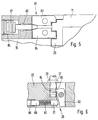
- Each of the two mold clamping jaws 26 has a clamping surface 32 which consists of a multiplicity of plungers 33 (clamping plungers) which can be moved hydraulically independently of one another by a certain stroke distance.
- plungers 33 clamping plungers
- FIG 3 one of the plungers 33 is shown in more detail, i. H. the corresponding area of the mold clamping jaw 26 is shown cut away.
- the inner end region of each tappet 33 is provided with a tappet piston 34, which is hydraulically displaceably arranged in a tappet cylinder 35.
- the cylinder space of the ram cylinder 35 can be closed by a hydraulically actuated shut-off valve 70.
- the required hydraulic distributors and hydraulic lines to the hydraulic connections 30 are not shown for the sake of simplicity.
- the shut-off valves 70 are moved hydraulically into the open position, so that hydraulic fluid can penetrate into the plunger cylinder 35 and move the plunger 33 outwards. Your movement is limited by the stop on a workpiece 71 to be clamped 3 is a turbine blade. Tappets 33 that do not come into contact with the workpiece 71 extend into their end position. After reaching the clamping position, the shut-off valves 70 are brought into their blocking position, so that the tappets 33 are fixed in the clamping position. Check valves, not shown, ensure that the shut-off valves 70 remain in the closed position even when the external pressure supply is lost. The mode of operation of the mold clamping jaws 26 is shown in more detail in the prior art specified at the outset.
- a tensioning band 72 which for example consists of a metal foil, extends over the tensioning surface 32.
- This clamping band runs in the longitudinal direction over the clamping surface 32 and is then deflected via deflection rollers 73 on both sides of the clamping surface 32 into the interior of the mold clamping jaw 26.
- the two ends of the tension band 72 are suspended in tension springs 74 which are fastened in the interior of the mold clamping jaw 26.
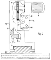
- a hydraulic connecting piece 75 is fixed to the base body 11 symmetrically to the slides 21, 22.
- this connecting piece 75 is opposed by a counter-connecting piece 76 which is arranged on the holding device 10 so as to be hydraulically displaceable.
- a hydraulic cylinder 77 in the interior of the counter connector 76.
- the hydraulic connections 78 are connected via channels (not shown) in the interior of the counter-connection piece 76 to connection openings 80 on the back of the counter-connection piece 76.
- These connection openings 80 can be connected to hydraulic lines (control and supply lines), not shown.
- the mating connector 76 is moved hydraulically and coupled to the connector 75.
- the base body 11 is fixed by a hydraulic parking brake 81, which is shown in more detail in FIG.
- the carriages 21, 22 are moved hydraulically against one another by applying pressure to corresponding pressure lines via the counter-connector 76.
- the internal lines that lead to the slide 21, 22 in the connector 75 are not shown in detail.
- the pressure connection between the connecting piece 75 and the displaceable slide 21, 22 takes place, for example, via displaceable pressure pipes 82, which are only shown schematically.
- the rams 33 are actuated or extended until the workpiece 71 is fixed between them in accordance with FIG. 3.
- the counter connector 26 is again from the connector 75 decoupled and moved back into the position shown in Figure 1.
- Check valves or other locking means ensure that the plunger 33 remain in their clamping position.
- the base body 11 can be rotated together with the clamped workpiece 71. This can be done by means of the drive motor 16, or when the workpiece 71 is rotated, the base body 11 is also rotated.
- the base body 11 is brought back into the basic position shown in FIG. 1 and locked, the mating connector 76 is coupled to the connector 75 and the workpiece is released by moving the plunger 33 and slide 21, 22 back.
- the parking brake 81 shown in more detail in FIG. 5 essentially consists of two pivotably mounted brake shoes 83, 84 which grip around the base body 11 at its bearing area. From the opposite side, a tapered release pin 85 engages between the brake shoes 83, 84. This release pin 85 carries at the opposite end a piston 87 movable in a hydraulic cylinder chamber 86. To brake or lock the base body 11, the cylinder chamber 86 is acted upon by hydraulic pressure, so that the piston 87 and thus the release pin 85 moves toward the base body 11 . Due to the tapered end of the release pin 85, the two brake shoes 83, 84 are spread apart at this point, so that they are on the opposite side due to their swivel mounting Pinch the base 11 between them and hold it in the active end area.
- FIG. 6 shows one of the locking devices 29 for one of the retaining bolts 27 of the mold clamping jaw 26 in the slide 22 in greater detail.
- a holding end is first machined on a corresponding blank in a machining center.
- the blank is then clamped on this, and the curved blade surfaces are produced in a known manner in one or more machining operations. Since the opposite holding end still to be machined is relatively far from the clamped holding end, problems would arise during its machining without further measures. These are the inventive Clamping device released.
- the holding device 10 is first shifted in the longitudinal direction to such an extent that it is positioned next to the machined blade surfaces. Longitudinal guides 95 are used for this purpose, only one of which is shown for simplification. The motor drive for moving the holding device 10 along these longitudinal guides 95 is likewise not shown.
- the holding device 10 is moved on transverse guides 96 transversely to the longitudinal direction of the partially machined turbine blade, which reaches the clamping opening 13 through the recess 14.
- the motor drive for the transverse guides 96 is again not shown for the sake of simplicity.
- the holding device 10 is thus positioned so that the longitudinal axis of the partially machined turbine blade, that is, the longitudinal axis of the already machined holding end of this turbine blade coincides with the axis of rotation of the base body 11. Any necessary adjustment devices for height adjustment of the holding device 10 must of course also be provided if necessary.
- the turbine blade is clamped in the base body 11 with the aid of the mold clamping jaws 26 in the manner already described. Now the still unprocessed holding end of the turbine blade can be processed.
- the partially machined turbine blade can be rotated in the required manner with the aid of the drive motor 16, this rotation also being able to take place via the clamped, already machined holding end of the turbine blade.
- the mold clamping jaws 26 are released in the angular position of the base body 11 shown in FIG. 1, and the holding device 10 is released laterally from the turbine blade moved away. The next turbine blade can now be clamped and the process described is repeated.
- mold jaws 26 of different shapes are accommodated in a magazine (not shown). These can be placed on the sled 21, 22 as required, for. B. by means of a change machine, also not shown.
- the carriages 21, 22 can also be dispensed with, i. H. the mold clamping jaws 26 are placed directly on the base body 11. The clamping movement is then effected solely by the movement of the plunger 33.
- locking devices are provided in a manner known per se, which can also have hydraulic cylinders, for example.
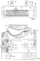
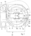
- the second exemplary embodiment shown in FIG. 7 has many individual parts and devices which correspond to those of the first exemplary embodiment.
- the same or equivalent components, assemblies or devices are therefore provided with the same reference numerals and are not described again.
- a holding device 100 consists of two sections 100a, 100b, the section 100b being pivotably mounted on the section 100a via a swivel joint 101, while the section 100a is in a manner corresponding to the holding device 10 of the first embodiment on the in FIG Figure 7 not shown transverse guides 96 is guided, which in turn is movable along the longitudinal guides 95.
- Motorized adjusting devices can also be provided here.
- the two sections 100a and 100b of the holding device 100 together have a shape which essentially corresponds to that of the holding device 10 of the first exemplary embodiment.
- a dividing line 102 or contact surface between the two sections 100a, 100b runs obliquely downwards from the swivel joint 101 arranged at the top left.
- a circular disk-shaped base body 104 is rotatably mounted in this holding device, which also consists of two sections 104a, 104b. In the illustrated rotational position of the base body 104, the dividing line 102 continues through this base body 104 and divides it into the two sections 104a, 104b.
- an axially continuous clamping opening 103 is again provided for receiving workpieces to be clamped, the two mold clamping jaws 26 being arranged on both sides of this clamping opening 103 and each section 104a, 104b carrying such a mold clamping jaw 26.
- the movement of the mold clamping jaws 26 and the plunger 33 takes place according to the first exemplary embodiment, i. H. hydraulically via the connection piece 75 and the counter-connection piece 76 which can be moved relative to this. While the hydraulic lines from the connection piece 75 can be guided in a manner not shown through the section 104a of the base body 104 to its mold clamping jaws 26, the hydraulic feeds to the other mold clamping jaws 26 on the other section 104b across the dividing line 102. This can be done via movable external lines, not shown, or via hydraulic lines integrated in the section 104b, the hydraulic connections being formed across the separating surface formed by the dividing line 102, which sealingly abut one another in the closed state of the sections 104a, 104b.
- the base body 104 has on its circumference a turntable 105 which in turn consists of two parts and, as in the first exemplary embodiment, is rotatably mounted in the holding device 100 via bearing rollers 12.
- the bearing rollers 12 engage in a manner not shown in the turntable 105, wherein engaging elements in or on this turntable 105 prevent the two sections 104a, 104b of the base body 104 from falling out of the holding device 100 in the open state.
- These engaging elements can also be the bearing rollers 12 themselves.
- the drive motor 16 provided with the gear 17 in turn drives the gear rim 20 of the base body 104 via a drive gear 18, which here is inside of the slewing ring 105 or behind it.
- the second drive gear 19 can be omitted here, since the base body 104 and thus the slewing ring 105 each form a closed ring.
- two parking brakes (not shown) are provided for the two sections 104a, 104b, which essentially correspond to the parking brake 81 of the first exemplary embodiment.
- the upper section 100b of the holding device 100 is pivoted upwards together with the upper section 104b of the base body 104. In the open position pivoted upward, the upper section 100b of the holding device 100 then assumes the position shown in broken lines in FIG.
- a hydraulic actuator 106 which is only shown schematically next to the swivel joint 101, is used for automatically controlled swiveling up.
- a plunger 107 of this hydraulic actuator 106 which is arranged in the upper section 100b of the holding device 100, presses the actuating surface of the lower section 100a formed by the dividing line 102 and thereby presses the two sections apart.
- the return movement can be done by gravity, by spring force or also hydraulically.
- another fluidic actuator or a magnetic or electrical actuator instead of a hydraulic actuator another fluidic actuator or a magnetic or electrical actuator.
- a hydraulic locking device 108 is used for this purpose, which is arranged on the edge region of the dividing line 102 that is distant from the swivel joint 101.
- a plunger 109 which tapers at the free end and is hydraulically displaceably mounted in the lower section 100a, engages with a tapered end between two locking members 110. If the plunger 109 moves toward the upper section 100b, the locking members 110 are pressed apart and engage in locking openings 111 in the upper section 100b for locking.
- other known designs of locking devices can also be provided here.
Landscapes
- Engineering & Computer Science (AREA)
- Mechanical Engineering (AREA)
- Jigs For Machine Tools (AREA)
- Mounting, Exchange, And Manufacturing Of Dies (AREA)
- Gripping Jigs, Holding Jigs, And Positioning Jigs (AREA)
Applications Claiming Priority (4)
| Application Number | Priority Date | Filing Date | Title |
|---|---|---|---|
| DE19515894 | 1995-04-29 | ||
| DE19515894 | 1995-04-29 | ||
| DE19539488A DE19539488A1 (de) | 1995-04-29 | 1995-10-24 | Spannvorrichtung zum umfangsseitigen Spannen von Werkstücken mit beliebiger Umfangskontur |
| DE19539488 | 1995-10-24 |
Publications (3)
| Publication Number | Publication Date |
|---|---|
| EP0739672A2 true EP0739672A2 (fr) | 1996-10-30 |
| EP0739672A3 EP0739672A3 (fr) | 1997-09-24 |
| EP0739672B1 EP0739672B1 (fr) | 1999-09-29 |
Family
ID=26014765
Family Applications (1)
| Application Number | Title | Priority Date | Filing Date |
|---|---|---|---|
| EP96104857A Expired - Lifetime EP0739672B1 (fr) | 1995-04-29 | 1996-03-27 | Dispositif de serrage à serrer des pièces à travailler avec une surface non-réguliere |
Country Status (4)
| Country | Link |
|---|---|
| US (1) | US5690323A (fr) |
| EP (1) | EP0739672B1 (fr) |
| JP (1) | JPH08300235A (fr) |
| AT (1) | ATE185097T1 (fr) |
Cited By (9)
| Publication number | Priority date | Publication date | Assignee | Title |
|---|---|---|---|---|
| EP0847847A1 (fr) * | 1996-12-11 | 1998-06-17 | CKD Corporation | Dispositif pour la connexion de tuyaux |
| FR2779676A1 (fr) * | 1998-06-10 | 1999-12-17 | Michel Pioch | Dispositif de bridage et orientation pour l'usinage d'un profile |
| WO2010130590A3 (fr) * | 2009-05-15 | 2011-01-20 | Technische Universität München | Procédé et dispositif destinés à retenir et à usiner une pièce |
| EP2584191A4 (fr) * | 2010-06-16 | 2014-05-07 | Naditec Ingenieria S L | Lunette améliorée pour le support rotatif de pales d'aérogénérateurs |
| CN111590514A (zh) * | 2020-05-22 | 2020-08-28 | 安徽省繁昌县皖南阀门铸造有限公司 | 一种蝶阀专用可调式铸造法兰安装连接组件 |
| WO2021009485A1 (fr) * | 2019-07-15 | 2021-01-21 | Bae Systems Plc | Appareil de fabrication |
| CN112621284A (zh) * | 2020-12-07 | 2021-04-09 | 上海交大智邦科技有限公司 | 加工夹具 |
| EP3978187A1 (fr) * | 2020-09-30 | 2022-04-06 | Rolls-Royce plc | Système de serrage |
| EP3995253A1 (fr) * | 2020-11-04 | 2022-05-11 | GF Machining Solutions AG | Dispositif de stabilisation d'une pièce à usiner dans une machine outil |
Families Citing this family (20)
| Publication number | Priority date | Publication date | Assignee | Title |
|---|---|---|---|---|
| DE19702848C1 (de) * | 1997-01-27 | 1998-02-12 | Hubert W Meintrup | Haltevorrichtung für Werkstücke |
| DE19816014B4 (de) * | 1998-04-09 | 2007-10-31 | Volkswagen Ag | Spannvorrichtung für die Halterung von Karosseriebauteilen |
| US6305678B1 (en) | 2000-06-02 | 2001-10-23 | Hammersmith Mfg. & Sales, Inc. | Welder positioner |
| JP2002301631A (ja) * | 2000-12-26 | 2002-10-15 | Inst Of Physical & Chemical Res | 長尺薄肉形材の加工装置と加工設備 |
| US6679503B2 (en) * | 2001-01-11 | 2004-01-20 | Yamazaki Mazak Kabushiki Kaisha | Chuck unit for machine tool |
| DE10203128A1 (de) * | 2002-01-25 | 2003-07-31 | Hans Funk Gmbh Stahl Und Metal | Vorrichtung zum Spannen von Behältern |
| DE10237233B4 (de) * | 2002-08-14 | 2006-07-13 | Daimlerchrysler Ag | Spanneinrichtung einer Feinbearbeitungsvorrichtung und Verfahren zum verformungsangepassten Feinbearbeiten eines Werkstücks unter Einsatz der Spanneinrichtung |
| US8518051B2 (en) * | 2003-05-16 | 2013-08-27 | Mazor Robotics Ltd. | Robotic total/partial knee arthroplastics |
| US8496237B2 (en) * | 2007-05-31 | 2013-07-30 | Rolle Industries Pty Ltd | Apparatus for fabrication of structural members |
| KR101022648B1 (ko) * | 2008-08-07 | 2011-03-22 | 한국전력공사 | 고 중량물을 회전시키기 위한 방법 및 장치 |
| US8714536B2 (en) * | 2010-05-05 | 2014-05-06 | The Gleason Works | Cradle for machining of large pinions |
| FR2976836B1 (fr) * | 2011-06-21 | 2013-06-21 | Snecma | Dispositif de maintien d'une aube de turbomachine en vue d'un usinage |
| CN102626874A (zh) * | 2012-04-12 | 2012-08-08 | 江苏中港冶金设备科技有限公司 | 切管机的夹持机构 |
| DE102012211877B4 (de) * | 2012-07-06 | 2016-09-29 | Wobben Properties Gmbh | Vorrichtung zum Handhaben eines Windenergieanlagen-Rotorblattes |
| JP6201934B2 (ja) * | 2014-08-27 | 2017-09-27 | トヨタ紡織株式会社 | 内装材用作業台 |
| DE102015101599B3 (de) * | 2015-02-04 | 2016-05-19 | Matrix Gmbh Spannsysteme Und Produktionsautomatisierung | Greifkopf |
| DE102018112028A1 (de) * | 2018-05-18 | 2019-11-21 | Tmd Friction Services Gmbh | Vorrichtung zur Fixierung von Werkstücken, Bearbeitungsanlage und Betätigungsvorrichtung |
| US10913133B2 (en) * | 2018-07-02 | 2021-02-09 | Raytheon Technologies Corporation | Processes and tooling associated with diffusion bonding the periphery of a cavity-back airfoil |
| JP2020131331A (ja) * | 2019-02-18 | 2020-08-31 | 株式会社Ihi | ブレード把持治具 |
| US20240167506A1 (en) * | 2022-11-22 | 2024-05-23 | GM Global Technology Operations LLC | System and method to protect a prefinished rotor journal of a rotor during a manufacturing process |
Family Cites Families (15)
| Publication number | Priority date | Publication date | Assignee | Title |
|---|---|---|---|---|
| US598332A (en) * | 1898-02-01 | Carpet and matting clamp for sewing-machines | ||
| US2113509A (en) * | 1937-03-23 | 1938-04-05 | Leblond Mach Tool Co R K | Crankshaft chuck |
| US2354794A (en) * | 1939-11-18 | 1944-08-01 | Walter A Buehler | Apparatus for manufacturing tanks and the like |
| DE871280C (de) * | 1945-10-15 | 1953-03-23 | Ernst Flueck | Schraubstock mit gegeneinander kippbaren oder in mehrere Spannfinger aufgeteilten Backen |
| US2985455A (en) * | 1960-03-07 | 1961-05-23 | Vernon R Powell | Tube gripping mechanism |
| US3436071A (en) * | 1966-04-04 | 1969-04-01 | Xerox Corp | Work holder |
| JPS524399B2 (fr) * | 1972-08-10 | 1977-02-03 | ||
| US3851869A (en) * | 1973-07-18 | 1974-12-03 | Savage W Co Inc | Rotatable chuck for supporting elongate work piece |
| DE3010096A1 (de) * | 1980-03-15 | 1981-09-24 | Maschinenfabrik Hilma Gmbh, 5912 Hilchenbach | Zusatzbacke fuer maschinenschraubstoecke |
| JP2511439B2 (ja) * | 1987-01-30 | 1996-06-26 | 豊田工機株式会社 | 工作物ロ−ルオ−バ−装置 |
| US4789146A (en) * | 1987-04-29 | 1988-12-06 | Andrew Kuei | Angle vise |
| US4976025A (en) * | 1989-09-22 | 1990-12-11 | Aldridge Jr Billie A | Test assembly for machine tool having hydraulic pallet assemblies |
| JPH0457635A (ja) * | 1990-06-25 | 1992-02-25 | Kitamura Mach Co Ltd | 工作機械 |
| DE4311110A1 (de) * | 1993-04-05 | 1994-10-06 | Goetz Metall Anlagen | Formspannbacken für eine Spannvorrichtung |
| US5407185A (en) * | 1993-08-26 | 1995-04-18 | Hughes Aircraft Company | Reconfigurable clamp |
-
1996
- 1996-03-27 AT AT96104857T patent/ATE185097T1/de not_active IP Right Cessation
- 1996-03-27 EP EP96104857A patent/EP0739672B1/fr not_active Expired - Lifetime
- 1996-04-16 US US08/633,187 patent/US5690323A/en not_active Expired - Fee Related
- 1996-04-25 JP JP8105934A patent/JPH08300235A/ja active Pending
Cited By (15)
| Publication number | Priority date | Publication date | Assignee | Title |
|---|---|---|---|---|
| EP0847847A1 (fr) * | 1996-12-11 | 1998-06-17 | CKD Corporation | Dispositif pour la connexion de tuyaux |
| US6026882A (en) * | 1996-12-11 | 2000-02-22 | Ckd Corporation | Tube connecting apparatus |
| EP0953431A3 (fr) * | 1996-12-11 | 2001-08-01 | Terumo Kabushiki Kaisha | Dispositif pour la connexion de tuyaux |
| US6341637B1 (en) | 1996-12-11 | 2002-01-29 | Terumo Kabushiki Kaisha | Tube connecting apparatus |
| FR2779676A1 (fr) * | 1998-06-10 | 1999-12-17 | Michel Pioch | Dispositif de bridage et orientation pour l'usinage d'un profile |
| WO2010130590A3 (fr) * | 2009-05-15 | 2011-01-20 | Technische Universität München | Procédé et dispositif destinés à retenir et à usiner une pièce |
| EP2584191A4 (fr) * | 2010-06-16 | 2014-05-07 | Naditec Ingenieria S L | Lunette améliorée pour le support rotatif de pales d'aérogénérateurs |
| WO2021009485A1 (fr) * | 2019-07-15 | 2021-01-21 | Bae Systems Plc | Appareil de fabrication |
| US11794294B2 (en) | 2019-07-15 | 2023-10-24 | Bae Systems Plc | Fabrication fixture |
| AU2020313393B2 (en) * | 2019-07-15 | 2025-10-30 | Bae Systems Plc | Fabrication fixture |
| CN111590514A (zh) * | 2020-05-22 | 2020-08-28 | 安徽省繁昌县皖南阀门铸造有限公司 | 一种蝶阀专用可调式铸造法兰安装连接组件 |
| EP3978187A1 (fr) * | 2020-09-30 | 2022-04-06 | Rolls-Royce plc | Système de serrage |
| EP3995253A1 (fr) * | 2020-11-04 | 2022-05-11 | GF Machining Solutions AG | Dispositif de stabilisation d'une pièce à usiner dans une machine outil |
| US11897069B2 (en) | 2020-11-04 | 2024-02-13 | Gf Machining Solutions Ag | Device for stabilizing a workpiece in a machine tool |
| CN112621284A (zh) * | 2020-12-07 | 2021-04-09 | 上海交大智邦科技有限公司 | 加工夹具 |
Also Published As
| Publication number | Publication date |
|---|---|
| EP0739672B1 (fr) | 1999-09-29 |
| EP0739672A3 (fr) | 1997-09-24 |
| JPH08300235A (ja) | 1996-11-19 |
| ATE185097T1 (de) | 1999-10-15 |
| US5690323A (en) | 1997-11-25 |
Similar Documents
| Publication | Publication Date | Title |
|---|---|---|
| EP0739672B1 (fr) | Dispositif de serrage à serrer des pièces à travailler avec une surface non-réguliere | |
| DE3610317C2 (fr) | ||
| DE2736412C2 (de) | Spannvorrichtung | |
| DE2257384C3 (de) | Spannfutter für Drehmaschinen u.dgl. Werkzeugmaschinen | |
| DE2310990C3 (de) | Einrichtung zum Umsetzen von Werkstücken mit einem Armstern, dessen Arme Greifer tragen | |
| EP1554079B1 (fr) | Dispositif de serrage pour des pieces allongees situees dans une machine d'usinage par laser | |
| DE4028775C1 (fr) | ||
| DE1477578B2 (de) | Numerisch gesteuerte werkzeugmaschine | |
| EP0013908B1 (fr) | Mandrin à mâchoires pivotantes pour machines à tourner | |
| EP1136179A2 (fr) | Système adaptif pour le serrage et la manipulation de pièces | |
| DE68920667T2 (de) | Automatischer Palettenwechsler. | |
| DE2926179C2 (fr) | ||
| EP3446816A1 (fr) | Mandrin de serrage pour roues | |
| DE4032881A1 (de) | Verfahren und vorrichtung zum einspannen eines werkstuecks | |
| DE19916765B4 (de) | Handhabungswerkzeug für eine Werkzeugmaschine | |
| EP3964332A1 (fr) | Dispositif de serrage | |
| EP2219811B1 (fr) | Dispositif pour serrer un porte-outil sur un mandrin de serrage pouvant être fixé sur une machine d'usinage | |
| DE19539488A1 (de) | Spannvorrichtung zum umfangsseitigen Spannen von Werkstücken mit beliebiger Umfangskontur | |
| DE19936502C1 (de) | Vorrichtung und Verfahren zur schwenkbaren Werkstückzuführung in den Arbeitsbereich einer Werkzeugmaschine | |
| DE68927402T2 (de) | Stanz- und Nibbel-Maschine mit automatischer Werkzeugschnellwechselvorrichtung | |
| EP0985477A1 (fr) | Dispositif de serrage | |
| EP1442832B1 (fr) | Dispositif de serrage pour serrer un boulon d'ancrage d'alimentation latèral des boules de serrage | |
| DE19631341B4 (de) | Verfahren und Vorrichtung zum Bereitstellen von Kränzen von plattenförmigen Schleifelementen zum Formen von rotierenden Bürsten | |
| DE19531104C2 (de) | Drehmaschinen-Spannfutter mit verstellbarer Exzentrizität | |
| DE10117951A1 (de) | Verfahren zum Wechseln eines rotationssymmetrischen Schneidwerkzeuges sowie Einrichtung zur Durchführung des Verfahrens |
Legal Events
| Date | Code | Title | Description |
|---|---|---|---|
| PUAI | Public reference made under article 153(3) epc to a published international application that has entered the european phase |
Free format text: ORIGINAL CODE: 0009012 |
|
| AK | Designated contracting states |
Kind code of ref document: A2 Designated state(s): AT CH DE ES FR GB IT LI NL SE |
|
| PUAL | Search report despatched |
Free format text: ORIGINAL CODE: 0009013 |
|
| AK | Designated contracting states |
Kind code of ref document: A3 Designated state(s): AT CH DE ES FR GB IT LI NL SE |
|
| 17P | Request for examination filed |
Effective date: 19971020 |
|
| GRAG | Despatch of communication of intention to grant |
Free format text: ORIGINAL CODE: EPIDOS AGRA |
|
| 17Q | First examination report despatched |
Effective date: 19981218 |
|
| GRAG | Despatch of communication of intention to grant |
Free format text: ORIGINAL CODE: EPIDOS AGRA |
|
| GRAH | Despatch of communication of intention to grant a patent |
Free format text: ORIGINAL CODE: EPIDOS IGRA |
|
| GRAH | Despatch of communication of intention to grant a patent |
Free format text: ORIGINAL CODE: EPIDOS IGRA |
|
| GRAA | (expected) grant |
Free format text: ORIGINAL CODE: 0009210 |
|
| RAP1 | Party data changed (applicant data changed or rights of an application transferred) |
Owner name: GOETZ GMBH |
|
| AK | Designated contracting states |
Kind code of ref document: B1 Designated state(s): AT CH DE ES FR GB IT LI NL SE |
|
| PG25 | Lapsed in a contracting state [announced via postgrant information from national office to epo] |
Ref country code: SE Free format text: THE PATENT HAS BEEN ANNULLED BY A DECISION OF A NATIONAL AUTHORITY Effective date: 19990929 Ref country code: NL Free format text: LAPSE BECAUSE OF FAILURE TO SUBMIT A TRANSLATION OF THE DESCRIPTION OR TO PAY THE FEE WITHIN THE PRESCRIBED TIME-LIMIT Effective date: 19990929 Ref country code: ES Free format text: THE PATENT HAS BEEN ANNULLED BY A DECISION OF A NATIONAL AUTHORITY Effective date: 19990929 |
|
| REF | Corresponds to: |
Ref document number: 185097 Country of ref document: AT Date of ref document: 19991015 Kind code of ref document: T |
|
| REG | Reference to a national code |
Ref country code: CH Ref legal event code: EP |
|
| REF | Corresponds to: |
Ref document number: 59603199 Country of ref document: DE Date of ref document: 19991104 |
|
| GBT | Gb: translation of ep patent filed (gb section 77(6)(a)/1977) |
Effective date: 19991020 |
|
| ITF | It: translation for a ep patent filed | ||
| ET | Fr: translation filed | ||
| NLV1 | Nl: lapsed or annulled due to failure to fulfill the requirements of art. 29p and 29m of the patents act | ||
| PGFP | Annual fee paid to national office [announced via postgrant information from national office to epo] |
Ref country code: FR Payment date: 20000315 Year of fee payment: 5 |
|
| PGFP | Annual fee paid to national office [announced via postgrant information from national office to epo] |
Ref country code: GB Payment date: 20000316 Year of fee payment: 5 |
|
| PG25 | Lapsed in a contracting state [announced via postgrant information from national office to epo] |
Ref country code: AT Free format text: LAPSE BECAUSE OF NON-PAYMENT OF DUE FEES Effective date: 20000327 |
|
| PG25 | Lapsed in a contracting state [announced via postgrant information from national office to epo] |
Ref country code: LI Free format text: LAPSE BECAUSE OF NON-PAYMENT OF DUE FEES Effective date: 20000331 Ref country code: CH Free format text: LAPSE BECAUSE OF NON-PAYMENT OF DUE FEES Effective date: 20000331 |
|
| PLBE | No opposition filed within time limit |
Free format text: ORIGINAL CODE: 0009261 |
|
| STAA | Information on the status of an ep patent application or granted ep patent |
Free format text: STATUS: NO OPPOSITION FILED WITHIN TIME LIMIT |
|
| 26N | No opposition filed | ||
| REG | Reference to a national code |
Ref country code: CH Ref legal event code: PL |
|
| PG25 | Lapsed in a contracting state [announced via postgrant information from national office to epo] |
Ref country code: GB Free format text: LAPSE BECAUSE OF NON-PAYMENT OF DUE FEES Effective date: 20010327 |
|
| PGFP | Annual fee paid to national office [announced via postgrant information from national office to epo] |
Ref country code: DE Payment date: 20010427 Year of fee payment: 6 |
|
| GBPC | Gb: european patent ceased through non-payment of renewal fee |
Effective date: 20010327 |
|
| PG25 | Lapsed in a contracting state [announced via postgrant information from national office to epo] |
Ref country code: FR Free format text: LAPSE BECAUSE OF NON-PAYMENT OF DUE FEES Effective date: 20011130 |
|
| REG | Reference to a national code |
Ref country code: FR Ref legal event code: ST |
|
| PG25 | Lapsed in a contracting state [announced via postgrant information from national office to epo] |
Ref country code: IT Free format text: LAPSE BECAUSE OF NON-PAYMENT OF DUE FEES Effective date: 20050327 |
|
| PG25 | Lapsed in a contracting state [announced via postgrant information from national office to epo] |
Ref country code: DE Free format text: LAPSE BECAUSE OF NON-PAYMENT OF DUE FEES Effective date: 20060901 |