EP0739699A2 - Procédé pour préparer des poutres en treillis de renforcement à partir de barres d'acier et dispositif pour la mise en oeuvre du procédé - Google Patents
Procédé pour préparer des poutres en treillis de renforcement à partir de barres d'acier et dispositif pour la mise en oeuvre du procédé Download PDFInfo
- Publication number
- EP0739699A2 EP0739699A2 EP96106342A EP96106342A EP0739699A2 EP 0739699 A2 EP0739699 A2 EP 0739699A2 EP 96106342 A EP96106342 A EP 96106342A EP 96106342 A EP96106342 A EP 96106342A EP 0739699 A2 EP0739699 A2 EP 0739699A2
- Authority
- EP
- European Patent Office
- Prior art keywords
- feed path
- lattice
- transport
- lattice girder
- girders
- Prior art date
- Legal status (The legal status is an assumption and is not a legal conclusion. Google has not performed a legal analysis and makes no representation as to the accuracy of the status listed.)
- Withdrawn
Links
Images




Classifications
-
- B—PERFORMING OPERATIONS; TRANSPORTING
- B28—WORKING CEMENT, CLAY, OR STONE
- B28B—SHAPING CLAY OR OTHER CERAMIC COMPOSITIONS; SHAPING SLAG; SHAPING MIXTURES CONTAINING CEMENTITIOUS MATERIAL, e.g. PLASTER
- B28B23/00—Arrangements specially adapted for the production of shaped articles with elements wholly or partly embedded in the moulding material; Production of reinforced objects
- B28B23/02—Arrangements specially adapted for the production of shaped articles with elements wholly or partly embedded in the moulding material; Production of reinforced objects wherein the elements are reinforcing members
-
- B—PERFORMING OPERATIONS; TRANSPORTING
- B28—WORKING CEMENT, CLAY, OR STONE
- B28B—SHAPING CLAY OR OTHER CERAMIC COMPOSITIONS; SHAPING SLAG; SHAPING MIXTURES CONTAINING CEMENTITIOUS MATERIAL, e.g. PLASTER
- B28B17/00—Details of, or accessories for, apparatus for shaping the material; Auxiliary measures taken in connection with such shaping
-
- B—PERFORMING OPERATIONS; TRANSPORTING
- B28—WORKING CEMENT, CLAY, OR STONE
- B28B—SHAPING CLAY OR OTHER CERAMIC COMPOSITIONS; SHAPING SLAG; SHAPING MIXTURES CONTAINING CEMENTITIOUS MATERIAL, e.g. PLASTER
- B28B23/00—Arrangements specially adapted for the production of shaped articles with elements wholly or partly embedded in the moulding material; Production of reinforced objects
- B28B23/02—Arrangements specially adapted for the production of shaped articles with elements wholly or partly embedded in the moulding material; Production of reinforced objects wherein the elements are reinforcing members
- B28B23/022—Means for inserting reinforcing members into the mould or for supporting them in the mould
Definitions
- the invention relates to a method for processing lattice girders consisting of steel bars according to the preamble of claim 1 and a device for performing this method.
- Lattice girders of this type are used in the construction industry as reinforcement elements for prefabricated components such as ceiling panels, wall elements or the like.
- the lattice girders consist of an upper and a lower flange.
- the upper chord usually consists of a single steel bar, the lower chord of two steel bars; Upper and lower chord rods are arranged so that they form the corners of an isosceles triangle.
- the lower chord bars are connected to the upper chord bar by inclined webs, which consist of a steel of smaller diameter, which runs zigzag or undulating between the upper and lower chord bars and is welded to it.
- the lower flange bars are not directly connected to each other, so that the cross-section of the lattice girder appears as open A.
- Lattice girders are usually manufactured and delivered in fixed lengths, e.g. 14 m. For further use, they must then be tailored to the dimensions of the components. For this preparation, there are systems in which a lattice girder is transported from a lattice girder store to the infeed area of a feed path, from where it is fed in an axial feed to a cutting device and cut by it to the length required for further processing before it, again in axial feed, reaches the outlet area of the feed path. From there, the lattice girder cut to length then goes to an interim storage facility, from which it is later removed for further processing.
- the feed path consists of a number of rotating disks arranged one behind the other, onto each of which a lattice girder is straddled and transported in the direction of its longitudinal axis by rotating all the disks in the same direction. Since the feed force is only transmitted selectively by friction from the rotating disks to the lattice girder and the coefficient of friction steel to steel is low, the feed of the lattice girders is uneven and therefore unreliable, so that only low transport speeds can be achieved. At the end of the outfeed area of the feed path, the cut-to-length lattice girders reach an intermediate store by simply tipping over.
- the further processing of the cut-to-length lattice girders, ie their installation in formwork, is usually carried out in a so-called "pallet circulation system".
- a so-called "pallet circulation system” consists of a longitudinally oval transport path for flat formwork forms, which have floor plan dimensions from approximately 3 to 12 m and on which the areas of individual ceiling and wall elements are delimited by insert parts. In these areas are first crossing longitudinal and transverse bars for basic reinforcement and then the cut lattice girders to increase the bending and shear strength of the slab or Wall plates inserted.
- the transport of the cut-to-length lattice girders from the intermediate storage to the reinforcement station of the pallet orbit and the insertion into the formwork form are usually done manually.
- the object of the invention is therefore to improve the effectiveness and thus the economy of such systems, in particular to increase their performance in the unit of time.
- this object is achieved by a method according to claim 1.
- a device for performing the method is specified in claim 3.
- the basic idea of the invention is to forcibly transport the lattice girders in a controlled manner throughout the processing operations, in such a way that the transport unit of the previous transport operation transfers a lattice girder directly into the work area of the next transport unit.
- lifting or moving devices with high acceleration values for the respective transport processes such as lifting and lowering as well as longitudinal displacement, are used for the individual transport units, it is not only possible to increase the transport speed on the feed path many times, for example by 0.4 m / sec. to about 4 m / sec., but also the transport units for combined lifting and moving operations Adjust speeds.
- electric motors are expediently used as drive means for the transport units, which are operatively connected to chain, rack or belt drives, that is to say means for the positive and thus reliable transmission of a torque in a linear movement.
- the pallet orbit is assigned to the system for processing the lattice girders in such a way that the axis of the transport path for the pallets runs parallel to the feed path for the lattice girders and the station for reinforcing the formwork is adjacent to the outlet area of the feed path . It is thereby achieved that the cut-to-length lattice girders can be lifted off the feed path by means of a lifting device and brought directly onto the formwork form and positioned thereon.
- this hoist must not only be able to perform lifting and lowering movements, but also movements in two horizontal directions offset by 90 degrees to one another and rotary movements about a vertical axis in order to position the cut-off lattice girders accordingly.
- the forced conveyance of the lattice girders proposed by the invention by means of its own lifting or displacement units, together with the use of electric motors for driving them, has in particular in connection with electronic length measuring devices, e.g. Encoders that allow precise positioning of the lifting, rotating and shifting units have the advantage that all transport processes, including the functions of the cutting and welding device, can be computer-controlled, so that the shortest possible machining times can be achieved.
- electronic length measuring devices e.g. Encoders that allow precise positioning of the lifting, rotating and shifting units have the advantage that all transport processes, including the functions of the cutting and welding device, can be computer-controlled, so that the shortest possible machining times can be achieved.
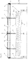
- I denotes the storage area for the lattice girders, II the feed area, which is divided into an inlet area IIa and an outlet area IIb, and III the reinforcement area in the course of a pallet orbit .
- II the feed area
- III the reinforcement area in the course of a pallet orbit .
- the storage area I and the reinforcement area III must run parallel to the feed area II, they can also be arranged in the opposite way to the illustration in FIG. 1.
- the storage area I comprises a Lattice girder storage 1 made up of a plurality of lattice girder stacks 4 arranged between vertical supports 2 on cross girders 3.
- Lattice girders of different sizes and thicknesses, but mostly of the same length, can be kept in stock, which can be removed from the top level as required.
- the cross members 3 can be removable, so that the underlying levels can be used for stocking lattice girders.
- the lattice girder bearing 1 and the feed area II arranged parallel to it are served with a feed path 5 by a transport unit T 1 .
- This consists of at least two, preferably three hoists 6, which are arranged at equal intervals on a cross member 7, which can be moved with carriages 8 in the direction of arrow 11 on rails on the upper longitudinal members 9 of two portals 10, which span the lattice girder bearing 1 and extend into the area of the feed path 5.
- the lifting devices 6 each comprise vertical lifting rods 13, which carry a cross member 14 at the lower end, on which grippers (not shown) are arranged for the clamping fixing of the upper chord bar 15a of a lattice girder 15.
- these grippers can be designed similarly to the clamping tools described below with reference to FIG. 4.
- the lifting rods 13 can be raised and lowered by means of toothed rack or chain gears. The torque required for this is generated by an electric motor 6a arranged on the cross member 7; the torque is transmitted to the hoists 6 by drive shafts 6b mounted on the cross member 7.
- the feed path 5 in the feed area II is shown in FIGS. 4 and 5.
- the feed path 5a essentially consists of the inlet area IIa a guide rail 17 mounted on a longitudinal beam 16, onto which a lattice beam 15 can be placed astride.
- the lattice girder 15 is continuously held and guided on the upper edge of the guide rail 17.
- the longitudinal beam 16 rests on stands 18.
- a slide 21 can be moved parallel to the guide rail 17 and at a small lateral distance from it as a displacement unit V 1 on a rail 20 mounted on a longitudinal member 19.
- This displacement unit V 1 only needs to extend over part of the length of the feed path 5a itself, since a lattice girder resting on the guide rail 17 is pushed forward for cutting according to the length of the cut off parts.
- the carriage 21 has on a gripping arm 23, which can be pivoted about a vertical axis 22 by 180 degrees, a clamping tool 25 equipped with two clamping jaws 24.
- the clamping jaws 24 are intended and suitable for clamping an upper chord bar of a lattice girder 15 between them.
- the carriage 21 is movable along the rail 20, for example by means of a toothed belt or rod drive; during its movement it forcibly takes along the lattice girder 15 sliding on the upper edge of the guide rail 17.
- the guide rail 17 can also be provided in a kind of tandem on a transversely displaceable frame 26.
- the carriage 20 with the gripping tool 25 is arranged centrally between the two guide rails 17 and 17 ', so that the gripper arm 23 can operate both guide rails 17 and 17' by pivoting through 180 degrees. In this way, while a lattice girder 15 is moved on the rail 17, another lattice girder 15 'can already be placed on the guide rail 17' by means of the lifting device 6 and vice versa.
- FIG. 5 a cross section through the exit area IIb of the feed path 5b is shown in FIG. 5 on a larger scale.
- the guide rail 29 for the cut-to-length lattice girders 15 ′′ is designed here as an upwardly open receptacle with a U-shaped cross section; a lattice girder 15 ′′ can thus be moved in a sliding manner with its lower flange on the receptacle of the guide rail 29.
- the guide rail 29 is mounted in a height-adjustable manner on the longitudinal girder 16, which is in turn mounted on stands 18, e.g. by means of one or more spindle-lifting gear 30.
- the feed path 5b here also comprises, as a displacement unit V 2, a slide 31 which can be displaced on a travel rail and has a gripper arm 32, to which, similarly as shown in FIG.
- the carriage 31 is in turn displaceable along its travel rail 33 by means of a toothed belt or rod drive.
- Electric motors which can be controlled via rotary pulse generators, are expediently used as the drive for the two displacement units V 1 and V 2 of the inlet and outlet areas 5a and 5b of the feed path 5.
- This makes it possible to control the displacement units at exact positions. This is important on the one hand in order to feed the lattice girders 15 to the cutting device 27 or the welding device 28, but on the other hand also in order to position the cut lattice girders 15 '' in the outlet area IIb of the sliding track 5 such that they are taken over by the transport unit T 2 arranged there can to on the Formwork form to be placed.
- the transport unit T 2 in the exit area IIb of the feed path and in the reinforcement area III is shown in FIGS. 6 and 7 in cross-section or longitudinal section.
- the transport unit T 2 here comprises a hoist 34 which can be moved in the direction of an arrow 36 as a carriage with undercarriages along the lower flange of a cross member 35.
- the drive takes place by means of an electric motor via racks on the cross member 35 and gears on the carriage.
- the cross member 35 in turn can be moved in the direction of arrow 39 on rails 37 on the upper side of longitudinal members 38 which run in the direction of the lattice girder processing and which rest on stands 40 and form them with these frames.
- the traverse 35 is driven by means of an electric motor via racks on the rails 37 and gears on the traverse 35.
- the position or length measurement is again carried out here by means of rotary pulse generators.
- a lifting rod 41 is mounted on the lifting device 34, which can be raised and lowered in the direction of arrow 42, for example by means of a rack or chain drive (FIG. 7).
- a gripper bar 43 is arranged, which carries gripping tools (not specifically shown) for holding a lattice girder 15 ′′ cut to length.
- the gripping tools are designed similarly to the gripping tools 25 described with reference to FIGS. 4 and 5 with clamping jaws 24.
- the gripper bar 43 is held on the lifting rod 41 by means of a rotating ring 44 with a rotating cylinder in order to be able to rotate a lattice girder 15 ′′ about a vertical axis and to be able to pick it up and set it down in different positions.
- a rotating ring 44 with a rotating cylinder in order to be able to rotate a lattice girder 15 ′′ about a vertical axis and to be able to pick it up and set it down in different positions.
- only two positions come into question, namely 0 degrees and 90 degrees, depending on whether longitudinal members for ceiling elements or cross members for wall elements are to be installed.
- FIG. 6 it is indicated how the lifting device 34 receives a lattice girder 15 ′′ from the outlet area IIb of the feed path 5b and moves along the cross member 35 in order to place it on a concrete pallet 45 which can be moved horizontally along a pallet circulation path 46; the end position of the hoist 34 is indicated by dash-dotted lines in the left half of the illustration. All four travel axes of the transport unit T 2 (arrows 49 in FIG. 1) can be operated in parallel. The axis of the pallet orbit is indicated at 47. On the concrete pallet 45 there is already a basic reinforcement 48 consisting of longitudinal and transverse bars, which, as indicated, is supplemented according to the invention by the lattice girders 15 ′′.
- a basic reinforcement 48 consisting of longitudinal and transverse bars, which, as indicated, is supplemented according to the invention by the lattice girders 15 ′′.
- the concreting pallet 45 is then brought along the pallet circulation path 46 into a concreting station in a manner known per se.
Landscapes
- Engineering & Computer Science (AREA)
- Chemical & Material Sciences (AREA)
- Ceramic Engineering (AREA)
- Mechanical Engineering (AREA)
- Manufacturing & Machinery (AREA)
- Accessories And Tools For Shearing Machines (AREA)
- Specific Conveyance Elements (AREA)
- Carriers, Traveling Bodies, And Overhead Traveling Cranes (AREA)
Applications Claiming Priority (2)
| Application Number | Priority Date | Filing Date | Title |
|---|---|---|---|
| DE19515637 | 1995-04-28 | ||
| DE1995115637 DE19515637A1 (de) | 1995-04-28 | 1995-04-28 | Verfahren zum Bearbeiten von aus Stahlstäben bestehenden Gitterträgern sowie Einrichtung zum Durchführen des Verfahrens |
Publications (2)
| Publication Number | Publication Date |
|---|---|
| EP0739699A2 true EP0739699A2 (fr) | 1996-10-30 |
| EP0739699A3 EP0739699A3 (fr) | 1998-02-25 |
Family
ID=7760591
Family Applications (1)
| Application Number | Title | Priority Date | Filing Date |
|---|---|---|---|
| EP96106342A Withdrawn EP0739699A3 (fr) | 1995-04-28 | 1996-04-23 | Procédé pour préparer des poutres en treillis de renforcement à partir de barres d'acier et dispositif pour la mise en oeuvre du procédé |
Country Status (2)
| Country | Link |
|---|---|
| EP (1) | EP0739699A3 (fr) |
| DE (1) | DE19515637A1 (fr) |
Cited By (4)
| Publication number | Priority date | Publication date | Assignee | Title |
|---|---|---|---|---|
| CN106626052A (zh) * | 2017-02-24 | 2017-05-10 | 中民筑友科技投资有限公司 | 一种预应力钢筋拉线台车及预应力预制件生产线 |
| CN108284510A (zh) * | 2018-02-07 | 2018-07-17 | 北京好运达智创科技有限公司 | 水泥轨枕桁架钢筋自动安装装置 |
| CN118906226A (zh) * | 2024-08-31 | 2024-11-08 | 山西三建集团有限公司 | 一种弹卡式预制桩连接接头装置及其制造系统 |
| CN121552529A (zh) * | 2026-01-21 | 2026-02-24 | 浙江世润建创科技发展有限公司 | 盾构隧道预制装配式内部结构预制体系及施工方法 |
Family Cites Families (7)
| Publication number | Priority date | Publication date | Assignee | Title |
|---|---|---|---|---|
| AT387930B (de) * | 1983-05-31 | 1989-04-10 | Undrau Anstalt | Anlage zur herstellung grossformatiger stahlbeton-fertigteile |
| CH665382A5 (en) * | 1983-12-22 | 1988-05-13 | Emil Metzger | Continuous prodn. line for forming moulded structural elements - has conveyor which transports moulds under charging chute |
| AT379974B (de) * | 1984-06-29 | 1986-03-25 | Evg Entwicklung Verwert Ges | Vorrichtung zum ablaengen von traegerabschnitten gewuenschter laenge von aus einer intermittierend arbeitenden traegerschweissmaschine austretenden gittertraegern |
| DE3615460C1 (de) * | 1986-05-07 | 1987-10-01 | Loesch Manfred Dipl Ing | Vorrichtung zur Herstellung von Bewehrungen von fuer Bauzwecke vorgesehenen Platten aus Stahlbeton fuer Fertigdecken |
| DE3714581C2 (de) * | 1987-04-30 | 1995-04-27 | Hugo Bittlmayer | Vorrichtung zum lagerichtigen Anordnen vorgefertigter Bewehrungen in Stahlbetonelementdeckenplatten |
| DE29501319U1 (de) * | 1995-01-30 | 1995-06-08 | Theis, Klaus, Dr., 60596 Frankfurt | Verlegeeinrichtung für Gitterträger |
| DE29502417U1 (de) * | 1995-01-30 | 1995-04-13 | Theis, Klaus, Dr., 60596 Frankfurt | Verlegeeinrichtung für Bewehrungsstäbe |
-
1995
- 1995-04-28 DE DE1995115637 patent/DE19515637A1/de not_active Withdrawn
-
1996
- 1996-04-23 EP EP96106342A patent/EP0739699A3/fr not_active Withdrawn
Cited By (5)
| Publication number | Priority date | Publication date | Assignee | Title |
|---|---|---|---|---|
| CN106626052A (zh) * | 2017-02-24 | 2017-05-10 | 中民筑友科技投资有限公司 | 一种预应力钢筋拉线台车及预应力预制件生产线 |
| CN106626052B (zh) * | 2017-02-24 | 2022-11-15 | 中民筑友科技投资有限公司 | 一种预应力钢筋拉线台车及预应力预制件生产线 |
| CN108284510A (zh) * | 2018-02-07 | 2018-07-17 | 北京好运达智创科技有限公司 | 水泥轨枕桁架钢筋自动安装装置 |
| CN118906226A (zh) * | 2024-08-31 | 2024-11-08 | 山西三建集团有限公司 | 一种弹卡式预制桩连接接头装置及其制造系统 |
| CN121552529A (zh) * | 2026-01-21 | 2026-02-24 | 浙江世润建创科技发展有限公司 | 盾构隧道预制装配式内部结构预制体系及施工方法 |
Also Published As
| Publication number | Publication date |
|---|---|
| EP0739699A3 (fr) | 1998-02-25 |
| DE19515637A1 (de) | 1996-10-31 |
Similar Documents
| Publication | Publication Date | Title |
|---|---|---|
| DE69328391T3 (de) | Aufbewahrungsvorrichtung für Stangen | |
| EP0583282B1 (fr) | Station d'usinage pour pieces a usiner, en particulier carrosseries de vehicules dans une chaine de transfert | |
| DE3613956C2 (fr) | ||
| EP1405693B1 (fr) | dispositif d'usinage pour des pièces en bois | |
| DE69605551T2 (de) | Verfahren zum Schweissen mindestens eines Schienenstranges und Maschine zur Anwendung dieses Verfahrens | |
| EP0056143A1 (fr) | Machine de coupage de métal à enlèvement des pièces découpées et aimants de transport | |
| DE69202710T2 (de) | Anlage zum Auswählen und Biegen von Stangen für Bauaufgaben. | |
| EP2467233A1 (fr) | Procédé et dispositif pour manipuler des brames aux fins de meulage des surfaces de brames | |
| DE3705773A1 (de) | Verfahren zur justierung, befestigung und/oder bearbeitung von funktionsflaechen eines fahrwegs einer elektromagnetischen schnellbahn | |
| EP0495525A2 (fr) | Dispositif et procédé pour fabriquer des pièces de mur ou des tableaux muraux à l'aide de pierres de construction | |
| DE202008010202U1 (de) | Transporteinrichtung | |
| EP0745453A2 (fr) | Chargeur et déchargeur | |
| EP1488884A2 (fr) | Chaíne de production | |
| AT400340B (de) | Einrichtung zum verlegen von schwellen | |
| DE3232180C2 (de) | Stapelvorrichtung für langgestrecktes Gut | |
| DE2530419A1 (de) | Verfahren und foerderer zum transportieren von metallplatten | |
| EP0439680A2 (fr) | Procédé et dispositif pour transporter des objets le long d'une ligne de production | |
| EP0739699A2 (fr) | Procédé pour préparer des poutres en treillis de renforcement à partir de barres d'acier et dispositif pour la mise en oeuvre du procédé | |
| DE10233084A1 (de) | Vorrichtung und Verfahren zum Fördern von Karosserien | |
| DE4212903C2 (fr) | ||
| DE3624482A1 (de) | Vorrichtung fuer den vorschub von zu beschichtenden bauteilen | |
| EP2635399A2 (fr) | Dispositif pour usiner une pièce de grand format | |
| DE3717867C2 (fr) | ||
| DE4428611C2 (de) | Anlage zum thermischen Trennen von Metallwerkstücken | |
| EP0422422B1 (fr) | Méthode de chargement automatique d'un convoyeur de sol |
Legal Events
| Date | Code | Title | Description |
|---|---|---|---|
| PUAI | Public reference made under article 153(3) epc to a published international application that has entered the european phase |
Free format text: ORIGINAL CODE: 0009012 |
|
| AK | Designated contracting states |
Kind code of ref document: A2 Designated state(s): AT DE DK FR IT NL |
|
| PUAL | Search report despatched |
Free format text: ORIGINAL CODE: 0009013 |
|
| AK | Designated contracting states |
Kind code of ref document: A3 Designated state(s): AT DE DK FR IT NL |
|
| STAA | Information on the status of an ep patent application or granted ep patent |
Free format text: STATUS: THE APPLICATION IS DEEMED TO BE WITHDRAWN |
|
| 18D | Application deemed to be withdrawn |
Effective date: 19981101 |