EP0740032A1 - Nivelliermaschine und ihre Grundstruktur - Google Patents
Nivelliermaschine und ihre Grundstruktur Download PDFInfo
- Publication number
- EP0740032A1 EP0740032A1 EP96200218A EP96200218A EP0740032A1 EP 0740032 A1 EP0740032 A1 EP 0740032A1 EP 96200218 A EP96200218 A EP 96200218A EP 96200218 A EP96200218 A EP 96200218A EP 0740032 A1 EP0740032 A1 EP 0740032A1
- Authority
- EP
- European Patent Office
- Prior art keywords
- disc
- levelling
- levelling machine
- base structure
- flattening
- Prior art date
- Legal status (The legal status is an assumption and is not a legal conclusion. Google has not performed a legal analysis and makes no representation as to the accuracy of the status listed.)
- Granted
Links
- 238000005498 polishing Methods 0.000 claims description 40
- 230000007704 transition Effects 0.000 claims description 16
- 229910052751 metal Inorganic materials 0.000 claims description 7
- 239000002184 metal Substances 0.000 claims description 7
- 230000008859 change Effects 0.000 claims description 5
- 230000006870 function Effects 0.000 claims description 5
- 230000008901 benefit Effects 0.000 description 10
- 239000000463 material Substances 0.000 description 9
- 229910000831 Steel Inorganic materials 0.000 description 4
- 239000010959 steel Substances 0.000 description 4
- 238000010276 construction Methods 0.000 description 3
- 230000000694 effects Effects 0.000 description 3
- 238000000034 method Methods 0.000 description 2
- 229910000838 Al alloy Inorganic materials 0.000 description 1
- UHOVQNZJYSORNB-UHFFFAOYSA-N Benzene Chemical compound C1=CC=CC=C1 UHOVQNZJYSORNB-UHFFFAOYSA-N 0.000 description 1
- 239000004593 Epoxy Substances 0.000 description 1
- FYYHWMGAXLPEAU-UHFFFAOYSA-N Magnesium Chemical compound [Mg] FYYHWMGAXLPEAU-UHFFFAOYSA-N 0.000 description 1
- 238000005299 abrasion Methods 0.000 description 1
- 239000000654 additive Substances 0.000 description 1
- 238000004873 anchoring Methods 0.000 description 1
- 239000003086 colorant Substances 0.000 description 1
- 239000011521 glass Substances 0.000 description 1
- 238000001746 injection moulding Methods 0.000 description 1
- 238000009434 installation Methods 0.000 description 1
- 239000007788 liquid Substances 0.000 description 1
- 229910052749 magnesium Inorganic materials 0.000 description 1
- 239000011777 magnesium Substances 0.000 description 1
- 239000000203 mixture Substances 0.000 description 1
- 230000003647 oxidation Effects 0.000 description 1
- 238000007254 oxidation reaction Methods 0.000 description 1
- 239000011049 pearl Substances 0.000 description 1
- 239000000049 pigment Substances 0.000 description 1
- 239000011505 plaster Substances 0.000 description 1
- 230000002265 prevention Effects 0.000 description 1
- 230000008569 process Effects 0.000 description 1
- 230000009993 protective function Effects 0.000 description 1
- 239000010453 quartz Substances 0.000 description 1
- 239000002994 raw material Substances 0.000 description 1
- 239000004576 sand Substances 0.000 description 1
- VYPSYNLAJGMNEJ-UHFFFAOYSA-N silicon dioxide Inorganic materials O=[Si]=O VYPSYNLAJGMNEJ-UHFFFAOYSA-N 0.000 description 1
- 239000000126 substance Substances 0.000 description 1
- 239000002023 wood Substances 0.000 description 1
Images

Classifications
-
- E—FIXED CONSTRUCTIONS
- E04—BUILDING
- E04F—FINISHING WORK ON BUILDINGS, e.g. STAIRS, FLOORS
- E04F21/00—Implements for finishing work on buildings
- E04F21/20—Implements for finishing work on buildings for laying flooring
- E04F21/24—Implements for finishing work on buildings for laying flooring of masses made in situ, e.g. smoothing tools
- E04F21/245—Rotary power trowels, i.e. helicopter trowels
- E04F21/248—Rotary power trowels, i.e. helicopter trowels used by an operator walking behind the trowel, i.e. walk-behind power trowels
Definitions
- This invention relates to a levelling machine, particularly for levelling and/or for polishing a floor layer, as well as a base structure hereby applied.
- this levelling machine can be applied for the treatment of any floor layer which is made from a flattened quantity of material, for example concrete, floor plaster, and so on.
- this levelling machine can also be applied for levelling and/or polishing of top layers based on plastic material, for example epoxy mortier, which, as is known, can be applied upon a sublayer of concrete or the like.
- plastic material for example epoxy mortier, which, as is known, can be applied upon a sublayer of concrete or the like.
- different additives may be added to such top layers, either by mixing in or by sprinkling over, such as magnesium, quartz, little glass pearls and so on, whereby decorative effects are achieved which show to full advantage particularly after being treated with a levelling machine.
- levelling machine can also be applied in order to flatten newly applied raw material, for example a mixture of sand and concrete, which at that time is still lying completely unflat.
- levelling machines provided with a rotating base structure which is formed by three or four or more flattening blades which are attached on a spider-shaped part.
- a polishing disc may be applied in place of using separate flattening blades, which disc will then be installed loosely under the spider-shaped part and the flattening blades and, during the rotation of the spider-shaped part, will be carried along by means of carrier elements, attached at the top side of the polishing disc, behind which elements the flattening elements are engaging.
- carrier elements attached at the top side of the polishing disc, behind which elements the flattening elements are engaging.
- a protection ring is necessary which has to prevent that the user of the machine might be touched by the flattening blades which are mounted at the ends of the spider-shaped part, and which simultaneously has to prevent that the flattening parts beat against the wall or other objects in the case that it is necessary to work alongside a wall or another object.
- a spider-shaped part also has the disadvantage that it is composed of different constructive parts, which, as far as the price is concerned, has a relatively large influence upon the total price of the levelling machine.
- the invention aims at providing a remedy for one or more of the aforementioned disadvantages. It also aims at a levelling machine which, according to a preferred form of embodiment, also in other points is more advantageous than the forms of embodiment known until now.
- the invention concerns a levelling machine, more particularly for levelling a floor layer, of the type whereby the levelling is performed by means of a rotating base structure, characterized in that this base structure comprises a support structure formed by a disc.
- this base structure comprises a support structure formed by a disc.
- the "support structure” is understood as the structure serving as a support between the flattening surface and the driven shaft of the machine.
- the disc which is functioning as support structure furthermore has the advantage that it can be carried out in a multifunctional manner, whereby is meant that it can, on option, be used as support structure for a flattening and/or polishing disc installed hereunder, or can be applied as such as a flattening and/or polishing element, whereby no separate second disc is necessary.
- the disc functioning as support structure is manufactured in plastic, while the optionally flattening and/or polishing disc installed hereunder preferably consists of metal, for example steel sheet.
- the invention of course also relates to the base structure itself, more particularly to the disc functioning as support structure, either in combination with e.g. a polishing disc mounted or mountable hereunder or not.
- Such base structure can, however, be sold separately and be mounted in exchange of the known embodiments upon existing machines.
- the invention relates to a levelling machine 1, more particularly for levelling a floor layer 2, of the type whereby the levelling is performed by means of a rotating base structure 3.
- the levelling machine 1 mainly consists of a motor 4, a reductor 5 and a control element 6 or such to move the machine over the floor layer 2 to be treated.
- the motor 4 can, as shown, be a thermic motor, for example a benzine motor, but can also be an electric motor which optionally is equipped with a frequency converter.
- the levelling machine 1 rests with the base structure 3 upon the floor layer 3, whereby during working this base structure 3 rotates over the floor layer 2 in a horizontal plane.
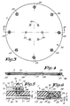
- the particularity of the invention consists in that the base structure 3 forms a support structure which is formed by a disc 7, which preferably has the shape of a circle and extends over the complete or almost complete working surface of the levelling machine 1.
- the disc 7 which functions as support structure is preferably carried out in a multifunctional manner, which means that it, as shown in the figures 1 and 2, can be applied as support structure for a flattening and/or polishing disc 8 installed hereunder as well as it can be applied itself as flattening and/or polishing element, whereby the flattening and/or polishing disc 8 is not present at all.
- the disc 7 which is shown in detail in the figures 3 and 4, preferably consists of plastic, with such a thickness, for example in the order of 20 mm, that it can perform the support function for which it is thought according to the invention.
- the flattening and/or polishing disc 8 preferably consists of metal, more particularly steel sheet with a minor thickness in order to limit weight.
- the base structure 3 is preferably fixed via the disc 7 at a therefore provided machine flange 9, by means of a quick change attachment.
- screw connections 10 formed by bolts 11, extending through the disc 7 and the machine flange 9, and wing nuts 12 are applied, such that these wing nuts 12 are easy attainable along the top side of the base structure 3.
- the bolts 11 are preferably fixed at the disc 7 such that they remain at their place also during the removal of the base structure 3.
- locknuts 13 can be applied which are screwed upon the bolts 11 from the top side 14 of the disc 7 and which can, for example, take place in recesses 15 which are provided in the bottom side of the machine flange 9.
- the bolts 11 are countersunk with their heads 16 into the bottom side 17 of the disc 7, due to which fact they do not form an obstacle for the installation of the flattening and/or polishing disc 8.
- the bolts 11 are countersunk such that they become located at a distance D from the bottom side 17 in order to prevent that these bolts 11 leave traces in the floor layer 2, even after the disc 7 might have become somewhat thinner due to abrasion.
- the base structure 3 is provided with fixation means which allow a preferably positive fixation between the disc 7 and the flattening and/or polishing disc 8.
- fixation means consists in the shown example in screw connections 18 which are arranged along the circumference of the base structure 3.
- screws 19 which are countersunk into the disc 7 can be applied which pass through the disc 7 from the top side and can be screwed into screw fittings 20 which are provided at the flattening and/or polishing disc 8.
- These screw fittings 20 consist in the shown example of nuts 21 which are provided at the top side of the flattening and/or polishing disc 8, which nuts 21 are welded onto the top side 23 by means of intermediate parts 22.
- the disc 7 itself preferably consists only of a plate of mainly constant thickness, with a number of openings 24 and 25 provided herein, respectively for the bolts 11 and the screws 19.
- disc 7 is particularly simple to realize by means of simple cutting techniques or by means of an injection moulding process.
- the disc 7 is preferably provided with at least one rounding 27, which is important in the case that the disc 7 is applied as flattening and/or polishing element.
- this rounding 27 is achieved that the levelling machine 1 becomes easier to steer, especially if a curve has to be made.
- the generation of so-called grinding marks, which are circle-shaped traces produced by the base structure, is hereby excluded.
- the rounding 27 preferably is a circle-shaped rounding.
- the rounding 27 may optionally be preceded by another rounding with a larger radius.
- the combination of the discs 7 and 8 are executed in such a way that they fit precisely into each other in order to obtain that the disc 7 exercises a centering effect onto the flattening and/or polishing disc 8.
- the flattening and/or polishing disc 8 is provided with a standing, preferably vertical edge 28 fitting precisely around the disc 7.
- the fact that the standing edge 28 is vertical enables working very narrowly alongside a wall.
- the flattening and/or polishing disc 8 is also provided with a rounding 29 which is preferably realized with a radius R2 of a circle, in order to avoid the so-called cutting.
- the flattening and/or polishing disc 8 comprises a support plane 30 having, next to the outward circumference, at least one inclined transition part, and still better, as shown in figure 2, two transition parts 31 and 32 showing straight lines in cross section, which parts form different angles A and B with the horizontal plane.
- the central part 33 in between these is preferably flat and extends perpendicular onto the rotation shaft 34.
- the transition part 31 serves for the prevention of the so-called cutting of the disc into the floor layer 2 and also offers the property that the material of the floor layer or, optionally, material to be polished into the floor layer 2, is easily drawn under the disc 8 and processed.
- the transition part 32 which extends under a smaller angle than the transition part 31 allows for the levelling machine 1 to turn into one or other direction simply by tipping, by exerting a suitable pressure onto the handle 6, without running the risk that the levelling machine eventually may gyrate away.
- angles A and B are, for example, of the order of 5 and 3 degrees, respectively.
- the radial length L1 of the transition part 31 is preferably considerably smaller than the radial length L2 of the transition part 32.
- the length L2 is preferably 1,5 up to 2,5 as large as L1.
- the radial length L3 of the central part is preferably equal to 0,5 up to 0,7 times the total length L4 of the radius of the base structure 3.
- transitions between the inclinations are gradual.
- the transition parts 31 and 32 may also consist of curved planes.
- the levelling machine 1 can easily be deducted from the figures and the aforegoing description.
- the flattening and/or polishing disc 8 or, in case this is not present, the disc 7 effects a levelling and/or polishing function on the floor layer 2.
- the base structure 3, for example, can also consist exclusively in a disc 7 having no provisions, such as openings 25, for the attachment of an underlying disc 8. It is also not excluded to fix the discs 7 and 8 to each other by means of a permanent connection.
- the aforementioned disc 7 can also consist of another material than plastic, such as wood or an aluminium alloy, whereby in that case a number of advantages will expire, which, of course, must not be a disadvantage if one wants to achieve a particular application.
Landscapes
- Engineering & Computer Science (AREA)
- Architecture (AREA)
- Civil Engineering (AREA)
- Structural Engineering (AREA)
- Soil Working Implements (AREA)
- Finish Polishing, Edge Sharpening, And Grinding By Specific Grinding Devices (AREA)
- Vehicle Body Suspensions (AREA)
- Machine Tool Units (AREA)
- Motor Or Generator Cooling System (AREA)
- Motor Or Generator Frames (AREA)
Applications Claiming Priority (2)
| Application Number | Priority Date | Filing Date | Title |
|---|---|---|---|
| BE9500387 | 1995-04-28 | ||
| BE9500387A BE1007950A6 (nl) | 1995-04-28 | 1995-04-28 | Egaliseermachine en onderstruktuur hierbij aangewend. |
Publications (2)
| Publication Number | Publication Date |
|---|---|
| EP0740032A1 true EP0740032A1 (de) | 1996-10-30 |
| EP0740032B1 EP0740032B1 (de) | 1999-10-20 |
Family
ID=3888946
Family Applications (1)
| Application Number | Title | Priority Date | Filing Date |
|---|---|---|---|
| EP96200218A Expired - Lifetime EP0740032B1 (de) | 1995-04-28 | 1996-02-01 | Nivelliermaschine |
Country Status (5)
| Country | Link |
|---|---|
| EP (1) | EP0740032B1 (de) |
| AT (1) | ATE185870T1 (de) |
| BE (1) | BE1007950A6 (de) |
| DE (1) | DE69604724T2 (de) |
| ES (1) | ES2140780T3 (de) |
Families Citing this family (2)
| Publication number | Priority date | Publication date | Assignee | Title |
|---|---|---|---|---|
| DE10146698C2 (de) * | 2001-09-21 | 2003-07-03 | Dieter Kerger | Glättscheibe |
| CN106245889B (zh) * | 2014-10-23 | 2018-09-21 | 泉州一锋机械有限公司 | 一种高效水泥砂浆喷涂机 |
Citations (6)
| Publication number | Priority date | Publication date | Assignee | Title |
|---|---|---|---|---|
| DE556874C (de) * | 1932-08-15 | Metallochemische Fabrik Akt Ge | Vorrichtung zum Glaetten des noch weichen Fussbodenbelages aus Asphalt oder Beton | |
| FR1100897A (fr) * | 1954-03-08 | 1955-09-26 | Perfectionnements aux outils pour le traitement des surfaces murales et analogues | |
| BE821515A (fr) * | 1974-10-25 | 1975-02-17 | Appareil de lissage d'un revetement a base de platre. | |
| FR2389731A1 (de) * | 1977-05-12 | 1978-12-01 | Dynapac Maskin Ab | |
| FR2553332A1 (fr) * | 1983-10-14 | 1985-04-19 | Giacomel Caterino | Procede et instrument pour aplanir, uniformiser et dresser une surface, en particulier surface murale ou sol |
| DE9010799U1 (de) * | 1990-07-19 | 1990-10-11 | Sicotan GmbH & Co KG, 4500 Osnabrück | Rotorglätter |
-
1995
- 1995-04-28 BE BE9500387A patent/BE1007950A6/nl not_active IP Right Cessation
-
1996
- 1996-02-01 ES ES96200218T patent/ES2140780T3/es not_active Expired - Lifetime
- 1996-02-01 DE DE69604724T patent/DE69604724T2/de not_active Expired - Fee Related
- 1996-02-01 AT AT96200218T patent/ATE185870T1/de not_active IP Right Cessation
- 1996-02-01 EP EP96200218A patent/EP0740032B1/de not_active Expired - Lifetime
Patent Citations (6)
| Publication number | Priority date | Publication date | Assignee | Title |
|---|---|---|---|---|
| DE556874C (de) * | 1932-08-15 | Metallochemische Fabrik Akt Ge | Vorrichtung zum Glaetten des noch weichen Fussbodenbelages aus Asphalt oder Beton | |
| FR1100897A (fr) * | 1954-03-08 | 1955-09-26 | Perfectionnements aux outils pour le traitement des surfaces murales et analogues | |
| BE821515A (fr) * | 1974-10-25 | 1975-02-17 | Appareil de lissage d'un revetement a base de platre. | |
| FR2389731A1 (de) * | 1977-05-12 | 1978-12-01 | Dynapac Maskin Ab | |
| FR2553332A1 (fr) * | 1983-10-14 | 1985-04-19 | Giacomel Caterino | Procede et instrument pour aplanir, uniformiser et dresser une surface, en particulier surface murale ou sol |
| DE9010799U1 (de) * | 1990-07-19 | 1990-10-11 | Sicotan GmbH & Co KG, 4500 Osnabrück | Rotorglätter |
Also Published As
| Publication number | Publication date |
|---|---|
| ATE185870T1 (de) | 1999-11-15 |
| BE1007950A6 (nl) | 1995-11-21 |
| DE69604724T2 (de) | 2000-05-18 |
| ES2140780T3 (es) | 2000-03-01 |
| DE69604724D1 (de) | 1999-11-25 |
| EP0740032B1 (de) | 1999-10-20 |
Similar Documents
| Publication | Publication Date | Title |
|---|---|---|
| KR100877224B1 (ko) | 추력방지 및 회전속도검출 기능이 구비된 폴리싱 머신용기어툴 박스 구조 | |
| US7144194B2 (en) | Surface finisher | |
| US12497776B2 (en) | Climbing wall assemblies | |
| US11866948B2 (en) | Offset mounting adapter for concrete surface processing tool | |
| US7059801B2 (en) | Metal plate reinforced plastic trowel blade for power troweling | |
| GB2159427A (en) | Mixing apparatus | |
| US11851894B2 (en) | Mounting adapter for concrete surface processing tools | |
| EP0740032B1 (de) | Nivelliermaschine | |
| US7104725B1 (en) | Concrete finishing attachment | |
| US20060083589A1 (en) | Hand-held power finisher | |
| AU2022204386B2 (en) | Potato peeling disc, food processor and method | |
| EP3313561B1 (de) | Mischvorrichtung | |
| CA2474775C (en) | Holding device for a protective cage of an outboard motor | |
| CN218590353U (zh) | 一种真石漆的混合装置 | |
| RU2056496C1 (ru) | Устройство для затирки штукатурного слоя и шлифовки поверхности | |
| CN214598617U (zh) | 一种建筑材料搅拌设备 | |
| AU695973B2 (en) | Accessories and attachments for angle grinder | |
| RU8910U1 (ru) | Погружной рабочий орган устройства для размельчения материала | |
| CN210057997U (zh) | 一种建筑装饰用高效搅拌机 | |
| CN213132749U (zh) | 一种真石漆混合装置 | |
| RU8907U1 (ru) | Погружной рабочий орган устройства для размельчения материала | |
| JP3024048U (ja) | 透水性樹脂舗装に於ける左官仕上げ機 | |
| JPH048926Y2 (de) | ||
| ITPR920019A1 (it) | Testa rotante con mole a settori oscillanti ad azionamento idraulico in macchina per lucidare e levigare marmi, graniti e pietre dure | |
| ITPR910016A1 (it) | Testa rotante con mole a settori oscillanti, in macchina per lucidare e levigare marmi, graniti e pietre dure. |
Legal Events
| Date | Code | Title | Description |
|---|---|---|---|
| PUAI | Public reference made under article 153(3) epc to a published international application that has entered the european phase |
Free format text: ORIGINAL CODE: 0009012 |
|
| AK | Designated contracting states |
Kind code of ref document: A1 Designated state(s): AT BE DE ES FR GB IE LU NL |
|
| 17P | Request for examination filed |
Effective date: 19970416 |
|
| 17Q | First examination report despatched |
Effective date: 19980916 |
|
| GRAG | Despatch of communication of intention to grant |
Free format text: ORIGINAL CODE: EPIDOS AGRA |
|
| GRAG | Despatch of communication of intention to grant |
Free format text: ORIGINAL CODE: EPIDOS AGRA |
|
| GRAH | Despatch of communication of intention to grant a patent |
Free format text: ORIGINAL CODE: EPIDOS IGRA |
|
| GRAH | Despatch of communication of intention to grant a patent |
Free format text: ORIGINAL CODE: EPIDOS IGRA |
|
| GRAA | (expected) grant |
Free format text: ORIGINAL CODE: 0009210 |
|
| AK | Designated contracting states |
Kind code of ref document: B1 Designated state(s): AT BE DE ES FR GB IE LU NL |
|
| REF | Corresponds to: |
Ref document number: 185870 Country of ref document: AT Date of ref document: 19991115 Kind code of ref document: T |
|
| REF | Corresponds to: |
Ref document number: 69604724 Country of ref document: DE Date of ref document: 19991125 |
|
| PGFP | Annual fee paid to national office [announced via postgrant information from national office to epo] |
Ref country code: AT Payment date: 19991215 Year of fee payment: 5 |
|
| ET | Fr: translation filed | ||
| PGFP | Annual fee paid to national office [announced via postgrant information from national office to epo] |
Ref country code: IE Payment date: 20000121 Year of fee payment: 5 |
|
| REG | Reference to a national code |
Ref country code: IE Ref legal event code: FG4D |
|
| REG | Reference to a national code |
Ref country code: ES Ref legal event code: FG2A Ref document number: 2140780 Country of ref document: ES Kind code of ref document: T3 |
|
| PLBE | No opposition filed within time limit |
Free format text: ORIGINAL CODE: 0009261 |
|
| STAA | Information on the status of an ep patent application or granted ep patent |
Free format text: STATUS: NO OPPOSITION FILED WITHIN TIME LIMIT |
|
| 26N | No opposition filed | ||
| PG25 | Lapsed in a contracting state [announced via postgrant information from national office to epo] |
Ref country code: IE Free format text: LAPSE BECAUSE OF NON-PAYMENT OF DUE FEES Effective date: 20010201 Ref country code: AT Free format text: LAPSE BECAUSE OF NON-PAYMENT OF DUE FEES Effective date: 20010201 |
|
| REG | Reference to a national code |
Ref country code: FR Ref legal event code: CA |
|
| REG | Reference to a national code |
Ref country code: FR Ref legal event code: RM |
|
| REG | Reference to a national code |
Ref country code: IE Ref legal event code: MM4A |
|
| REG | Reference to a national code |
Ref country code: GB Ref legal event code: IF02 |
|
| PGFP | Annual fee paid to national office [announced via postgrant information from national office to epo] |
Ref country code: GB Payment date: 20030203 Year of fee payment: 8 |
|
| PGFP | Annual fee paid to national office [announced via postgrant information from national office to epo] |
Ref country code: ES Payment date: 20030228 Year of fee payment: 8 |
|
| PG25 | Lapsed in a contracting state [announced via postgrant information from national office to epo] |
Ref country code: GB Free format text: LAPSE BECAUSE OF NON-PAYMENT OF DUE FEES Effective date: 20040201 |
|
| PG25 | Lapsed in a contracting state [announced via postgrant information from national office to epo] |
Ref country code: ES Free format text: LAPSE BECAUSE OF NON-PAYMENT OF DUE FEES Effective date: 20040202 |
|
| PGFP | Annual fee paid to national office [announced via postgrant information from national office to epo] |
Ref country code: DE Payment date: 20040417 Year of fee payment: 9 |
|
| GBPC | Gb: european patent ceased through non-payment of renewal fee |
Effective date: 20040201 |
|
| PGFP | Annual fee paid to national office [announced via postgrant information from national office to epo] |
Ref country code: LU Payment date: 20050119 Year of fee payment: 10 |
|
| PGFP | Annual fee paid to national office [announced via postgrant information from national office to epo] |
Ref country code: FR Payment date: 20050503 Year of fee payment: 10 |
|
| REG | Reference to a national code |
Ref country code: ES Ref legal event code: FD2A Effective date: 20040202 |
|
| PG25 | Lapsed in a contracting state [announced via postgrant information from national office to epo] |
Ref country code: DE Free format text: LAPSE BECAUSE OF NON-PAYMENT OF DUE FEES Effective date: 20050901 |
|
| PG25 | Lapsed in a contracting state [announced via postgrant information from national office to epo] |
Ref country code: LU Free format text: LAPSE BECAUSE OF NON-PAYMENT OF DUE FEES Effective date: 20060228 |
|
| REG | Reference to a national code |
Ref country code: FR Ref legal event code: ST Effective date: 20061031 |
|
| PG25 | Lapsed in a contracting state [announced via postgrant information from national office to epo] |
Ref country code: FR Free format text: LAPSE BECAUSE OF NON-PAYMENT OF DUE FEES Effective date: 20060228 |
|
| PGFP | Annual fee paid to national office [announced via postgrant information from national office to epo] |
Ref country code: NL Payment date: 20080227 Year of fee payment: 13 |
|
| PGFP | Annual fee paid to national office [announced via postgrant information from national office to epo] |
Ref country code: BE Payment date: 20080111 Year of fee payment: 13 |
|
| BERE | Be: lapsed |
Owner name: *B-MAC B.V.B.A. Effective date: 20090228 |
|
| NLV4 | Nl: lapsed or anulled due to non-payment of the annual fee |
Effective date: 20090901 |
|
| PG25 | Lapsed in a contracting state [announced via postgrant information from national office to epo] |
Ref country code: NL Free format text: LAPSE BECAUSE OF NON-PAYMENT OF DUE FEES Effective date: 20090901 |
|
| PG25 | Lapsed in a contracting state [announced via postgrant information from national office to epo] |
Ref country code: BE Free format text: LAPSE BECAUSE OF NON-PAYMENT OF DUE FEES Effective date: 20090228 |