EP0740219A2 - Entwicklungseinheit und Tonerbehälter - Google Patents
Entwicklungseinheit und Tonerbehälter Download PDFInfo
- Publication number
- EP0740219A2 EP0740219A2 EP96106446A EP96106446A EP0740219A2 EP 0740219 A2 EP0740219 A2 EP 0740219A2 EP 96106446 A EP96106446 A EP 96106446A EP 96106446 A EP96106446 A EP 96106446A EP 0740219 A2 EP0740219 A2 EP 0740219A2
- Authority
- EP
- European Patent Office
- Prior art keywords
- sleeve member
- inner sleeve
- outer sleeve
- toner
- opening
- Prior art date
- Legal status (The legal status is an assumption and is not a legal conclusion. Google has not performed a legal analysis and makes no representation as to the accuracy of the status listed.)
- Withdrawn
Links
Images


Classifications
-
- G—PHYSICS
- G03—PHOTOGRAPHY; CINEMATOGRAPHY; ANALOGOUS TECHNIQUES USING WAVES OTHER THAN OPTICAL WAVES; ELECTROGRAPHY; HOLOGRAPHY
- G03G—ELECTROGRAPHY; ELECTROPHOTOGRAPHY; MAGNETOGRAPHY
- G03G15/00—Apparatus for electrographic processes using a charge pattern
- G03G15/06—Apparatus for electrographic processes using a charge pattern for developing
- G03G15/08—Apparatus for electrographic processes using a charge pattern for developing using a solid developer, e.g. powder developer
- G03G15/0822—Arrangements for preparing, mixing, supplying or dispensing developer
- G03G15/0865—Arrangements for supplying new developer
- G03G15/0867—Arrangements for supplying new developer cylindrical developer cartridges, e.g. toner bottles for the developer replenishing opening
- G03G15/087—Developer cartridges having a longitudinal rotational axis, around which at least one part is rotated when mounting or using the cartridge
- G03G15/0872—Developer cartridges having a longitudinal rotational axis, around which at least one part is rotated when mounting or using the cartridge the developer cartridges being generally horizontally mounted parallel to its longitudinal rotational axis
-
- G—PHYSICS
- G03—PHOTOGRAPHY; CINEMATOGRAPHY; ANALOGOUS TECHNIQUES USING WAVES OTHER THAN OPTICAL WAVES; ELECTROGRAPHY; HOLOGRAPHY
- G03G—ELECTROGRAPHY; ELECTROPHOTOGRAPHY; MAGNETOGRAPHY
- G03G15/00—Apparatus for electrographic processes using a charge pattern
- G03G15/06—Apparatus for electrographic processes using a charge pattern for developing
- G03G15/08—Apparatus for electrographic processes using a charge pattern for developing using a solid developer, e.g. powder developer
- G03G15/0822—Arrangements for preparing, mixing, supplying or dispensing developer
- G03G15/0848—Arrangements for testing or measuring developer properties or quality, e.g. charge, size, flowability
- G03G15/0849—Detection or control means for the developer concentration
- G03G15/0855—Detection or control means for the developer concentration the concentration being measured by optical means
-
- G—PHYSICS
- G03—PHOTOGRAPHY; CINEMATOGRAPHY; ANALOGOUS TECHNIQUES USING WAVES OTHER THAN OPTICAL WAVES; ELECTROGRAPHY; HOLOGRAPHY
- G03G—ELECTROGRAPHY; ELECTROPHOTOGRAPHY; MAGNETOGRAPHY
- G03G15/00—Apparatus for electrographic processes using a charge pattern
- G03G15/06—Apparatus for electrographic processes using a charge pattern for developing
- G03G15/08—Apparatus for electrographic processes using a charge pattern for developing using a solid developer, e.g. powder developer
- G03G15/0822—Arrangements for preparing, mixing, supplying or dispensing developer
- G03G15/0865—Arrangements for supplying new developer
-
- H—ELECTRICITY
- H04—ELECTRIC COMMUNICATION TECHNIQUE
- H04N—PICTORIAL COMMUNICATION, e.g. TELEVISION
- H04N1/00—Scanning, transmission or reproduction of documents or the like, e.g. facsimile transmission; Details thereof
Definitions
- the present invention relates to electrostatic imaging devices such as copiers, facsimile machines, and laser printers, and more specifically to a cylindrical toner cartridge for installation therein.
- Copiers, facsimile machines, laser printers, and other imaging devices generally involve forming an electrostatic latent image on a photoreceptor drum by exposing the photoreceptor drum to a light source.
- imaging devices generally include a developing unit that includes a toner hopper for supplying toner.
- a detachable toner cartridge is installed in the toner hopper, and when the toner is depleted, the toner is replenished by changing the toner cartridge.
- Toner cartridges may be cylindrical in shape. This type of toner cartridge includes a cylindrical member in which the toner is stored, an opening on its peripheral surface through which the toner drops, and a removable sealing film which seals the opening.
- This type of cylindrical toner cartridge is installed in the toner hopper by inserting the toner cartridge into the toner hopper with the opening facing upward, peeling off the sealing film from the opening, and then rotating the toner cartridge 180° so that the toner flows out of the opening and into the toner hopper. The toner cartridge may then be rotated again so that any toner remaining in the toner cartridge falls into the toner hopper.
- toner tends to adhere to the sealing film, which can then soil the hands of the user when the sealing film is removed. Toner may also spill out of the toner cartridge and soil the area surrounding the imaging device. In addition, excess toner remaining in the spent cartridge can spill out when the toner cartridge is replaced.
- a developing unit for an imaging device includes a toner developing member, a toner cartridge and a toner hopper.
- the toner cartridge includes an inner sleeve member which has a first opening therethrough, and an outer sleeve member having a second opening therethrough.
- the toner hopper supplies toner to the toner developing member and supports the toner cartridge.
- the outer sleeve member is disposed around the outer circumference of the inner sleeve member and is relatively rotatable with respect to the inner sleeve member.
- An inner portion of the inner sleeve member is capable of storing toner, and the second opening in the outer sleeve member is alignable with the first opening in the inner sleeve member.
- toner from the toner hopper is supplied to the toner developing member, and an electrostatic latent image formed on a photoreceptor is developed by the toner developing member.
- the outer sleeve member of the empty toner cartridge is rotated so that the first opening is sealed by the outer sleeve member and the cartridge is then removed from the toner hopper.
- a new toner cartridge is then installed in the toner hopper with the first opening facing downward and with the first opening sealed by the outer sleeve member.
- the outer sleeve member is then rotated so that the two openings are aligned facing downward.
- the toner contained in the inner sleeve member is supplied to the toner hopper.
- the first opening is sealed by the outer sleeve member and unsealed by rotating the outer sleeve member. This reduces the likelihood of toner spills relative to the conventional structure, in which the opening is unsealed by peeling off the sealing film.
- the first opening is sealed when the toner cartridge is removed, so any toner remaining in the spent cartridge does not spill from the first opening when the toner cartridge is removed.
- the second opening faces upward during removal, any toner adhering to the vicinity of the second opening may not spill out.
- the developing unit further includes an inner sleeve rotation restricting member disposed on the toner hopper, and an engaging member disposed on an end surface of the inner sleeve member. Rotation of the inner sleeve member is restricted when the engaging member is engaged with the inner sleeve rotation restricting member.
- the engaging member disposed on the inner sleeve member engages the inner sleeve member rotation preventing member disposed on the toner hopper.
- Rotation of the inner sleeve member is restricted when the first opening is facing downward, thereby allowing only the outer sleeve member to rotate. Since the inner sleeve can be locked into or released from a position in which rotation is prevented simply by moving the cartridge in the axial direction, the outer sleeve member can be rotated simply and reliably during installation in order to align the two openings.
- the developing unit further includes a protrusion disposed on a circumferential surface of the outer sleeve member, and an outer sleeve rotation restricting member disposed on the toner hopper.
- the outer sleeve rotation restricting member engages the protrusion and restricts the rotation of the outer sleeve member to no more than 180° with respect to the inner sleeve member when the inner sleeve rotation restricting member and the engaging member are engaged.
- the outer sleeve member is integrally rotatable with the inner sleeve member when the inner sleeve rotation restricting member and the engaging member are disengaged and the first and second openings are aligned.
- the two openings can be aligned precisely.
- the outer sleeve member is permitted to rotate when the inner sleeve member rotation preventing member and the engaging member are disengaged and the two openings are aligned, the inner sleeve member can be rotated in tandem by rotating the outer sleeve member.
- any toner remaining in the interior of the inner sleeve member can reliably dispensed from the toner cartridge.
- the developing unit further includes a detachment preventing member disposed on the toner hopper.
- the detachment preventing member engages the protrusion on the outer sleeve member and prevents the outer sleeve member from being removed from the toner hopper when the first and second openings are aligned. Because the first opening is always sealed when the toner cartridge is removed, the possibility of toner spills is reduced.
- a toner cartridge for a developing unit in an imaging device includes a cylindrical inner sleeve member and a cylindrical outer sleeve member.
- the cylindrical inner sleeve member has a first opening formed in its surface which faces downward during installation into the developing unit.
- the cylindrical outer sleeve portion has a second opening formed in its surface that faces upward during installation.
- the cylindrical outer sleeve member is disposed around the outer circumference of the cylindrical inner sleeve member and is relatively rotatable with it. Toner may be stored in an inner portion of the cylindrical inner sleeve member, and the second opening in the cylindrical outer sleeve member is alignable with the first opening in the cylindrical inner sleeve member.
- the outer sleeve member is rotated to align the first opening and the second opening during installation, so that the toner contained in the inner sleeve member may flow into the toner hopper. Since the first opening is sealed by the outer sleeve member when the toner cartridge installed and removed, the likelihood of toner spills is reduced relative to the conventional structure, in which the opening is unsealed by peeling off a sealing film. In addition, since the first opening is sealed when the toner cartridge is removed, toner remaining in the spent cartridge does not spill from the first opening when the toner cartridge is removed. Since the second opening faces upwards, any toner adhering to the vicinity of the second opening may not spill out.
- the cylindrical toner cartridge further includes an inner sleeve rotation restricting member disposed on the developing unit, and an engaging member disposed on an end surface of the cylindrical inner sleeve member. Rotation of the cylindrical inner sleeve member is restricted when the engaging member is engaged with the inner sleeve rotation restricting member.
- the engaging member on the inner sleeve member engages the inner sleeve member rotation preventing member on the toner hopper.
- Rotation of the inner sleeve member is therefore prevented when the first opening is facing downward, and only the outer sleeve member is permitted to rotate. Since the inner sleeve can be locked into or released from a position in which rotation is prevented simply by moving the toner cartridge in the axial direction, the outer sleeve member can be rotated simply and reliably during installation in order to align the two openings.
- the cylindrical toner cartridge further includes a protrusion disposed on an outer circumference of the cylindrical outer sleeve member, with the protrusion capable of restricting rotation of the cylindrical outer sleeve member within the developing member.
- the protrusion also prevents the removal of the toner cartridge from the toner hopper when the first and second opening are aligned.
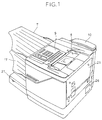
- a facsimile machine in accordance with one embodiment of the present invention includes a reader section 1 for reading image data from an original document, an output section 2 for forming received image data onto a paper surface, and a paper feed section 3 for feeding paper to the output section 2.
- a reader section 1 for reading image data from an original document
- an output section 2 for forming received image data onto a paper surface
- a paper feed section 3 for feeding paper to the output section 2.
- the present invention can be employed in a copier, laser printer, or any other similar type of imaging device.
- the reader section 1 includes an original document stand 5 on which an original document is placed, an original document transport section 6 for transporting the original document through the reader section 1, and an original discharge tray 7 for collecting the paper discharged from the original document transport section 6.
- the original document transport section 6 includes an image data reading sensor 8 for reading image data from an original document.
- a control panel 9, including various keys and a display for controlling and monitoring the functions of the facsimile machine, as well as a handset 10, are located on the upper portion of the facsimile machine.
- the output section 2 includes an aging unit 11 that includes a photoreceptor drum 30, a developing unit 12 for toner development of the electrostatic latent image formed on the photoreceptor drum 30, a transfer roller 13 for transferring the toner image formed on the photoreceptor drum 30 to a paper sheet, a laser device 15 for forming an cage corresponding to received data on the surface of the photoreceptor drum 30 of the imaging unit 11, and a fixing and transport device 16 for fixing the toner image which has been transferred to the paper surface by the transfer roller 13.
- a paper discharge tray 17 is located downstream from the fixing and transport device 16.
- the paper feed section 3 includes a paper cassette 21 that detachably inserts into an opening 20 in the lower section of the main body of the facsimile machine, and a paper feed device 22 that pulls paper sheets from the paper cassette 21 and feeds the paper sheets to the output section 2.
- the developing unit 12 includes a magnetic sleeve-type developing roller 33, a toner hopper 34 that supports the developing roller 33, and a toner cartridge 35 that is installed in the toner hopper 34.
- the main body of the device is divided into an upper case 25 and a lower case 26.
- the upper case 25 can be pivoted away from the lower case 26 by a hinge 27.
- the upper case 25 houses the reader section 1 and the imaging unit 11, the developing unit 12, and the laser device 15.
- the lower case 26 houses the transport roller 13, the fixing and transport device 16, and the paper feed section 3.
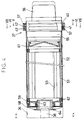
- the toner hopper 34 includes a cartridge installation hole 36 which supports the toner cartridge 35.
- the cartridge installation hole 36 is a cylindrical hole sized to conform to the outer diameter of the toner cartridge 35.
- An annular outer sleeve rotation regulating member 37 is disposed around the entrance of the cartridge installation hole 36 and restricts the rotation of the outer sleeve member of the toner cartridge 35 (described below).
- An inner sleeve rotation restricting member 38 is disposed in the bottom of the cartridge installation hole 36 and restricts the rotation of the inner sleeve member of the toner cartridge 35, as described below in greater detail.
- Fig. 4 shows a cross section of a portion of the cartridge installation hole 36 and the toner cartridge 35.
- a first notch 40 is formed on an outer portion of the outer sleeve rotation regulating member 37.
- the interior of the outer sleeve member rotation regulating member 37 is hollow, and is divided into a forward space 42 and a rear space 43 by a partition 41.
- the forward space 42 includes a first barrier 44 and a second barrier 45 that are disposed on the left side thereof and extend in the vertical direction.
- the gap between the distal end portions of the first and second barriers 44 and 45 is equal to the circumferential width of the first notch 40.
- the partition 41 includes second notch 46 and third notch 47 formed on the left and right sides thereof. Both second and third notches 46 and 47 are shaped identically to the first notch 40. As shown in Fig. 7, the rear space 43 includes third barrier 48 and fourth barrier 49, which are disposed on the left and right sides thereof and extend in the vertical direction.
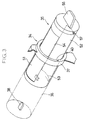
- the toner cartridge 35 includes an inner sleeve member 51 and an outer sleeve member 52.
- Outer sleeve member 52 is disposed around the outer circumference of the inner sleeve member 51 and is capable of both relative rotation and integral rotation with respect to the inner sleeve member 51.
- a first opening 53 is formed in the inner sleeve member 51 and faces downward when the toner cartridge 35 is installed.
- a second opening 54 is formed in the outer sleeve member 52 and can be aligned with the first opening 53.
- a first end of the outer sleeve member 52 is sealed by a first lid 55.
- a tab 56 for rotating outer sleeve member 52 is attached to the front end surface of the first lid 55.
- An engaging protrusion 57 is attached to an outer circumference of the first lid 55 and is disposed on the left side of the first lid 55 when the second opening 54 is facing upward.
- the engaging protrusion 57 is shaped to fit into the first, second and third notches 40, 46, and 47.
- a second end of the outer sleeve member 52 is sealed by a second lid 58.
- a support hole 59 is formed in the center of the second lid 58 and supports the inner sleeve member 51 so as to allow it to rotate freely.
- a first end of the inner sleeve member 51 is sealed by a third lid 61 and a second end thereof is sealed by a fourth lid member 62.
- the central portion of the fourth lid member 62 includes a ring-shaped support member 63 which protrudes outwards and engages the support hole 59.
- a pair of engaging plates 64 are disposed on the inside peripheral surface of the support member 63 and include a gap therebetween for engaging the inner sleeve rotation restricting member 38.
- a felt sealing member 65 is adhered to the perimeter of the first opening 53 and contacts an inner circumferential surface of the outer sleeve member 52 when the toner cartridge 35 is assembled together.
- the sealing member 65 prevents the toner contained in the inner sleeve member 51 from spilling into the outer sleeve member 52.
- the upper case 25 of the facsimile machine is opened to exposed the developing unit 12.
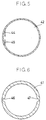
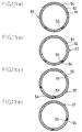
- the tab 56 attached on the outer sleeve member 52 is grasped and the outer sleeve member 52 is rotated 180° in the counterclockwise direction (to the position shown in Fig. 8).
- the inner sleeve rotation restricting member 38 is engaged by the engaging plates 64, and therefore the outer sleeve member 52 rotates with respect to the inner sleeve member 51.
- the first opening 53 which remains facing downward, is sealed by the outer sleeve member 52 because the second opening 54 is positioned facing upward.
- the engaging protrusion 57 attached to the first lid 55 of the outer sleeve member 52 moves to the location shown in Fig. 8.
- the engaging protrusion 57 is positioned within the rear space 43 and can pass through the first and second barriers 44 and 45 disposed in the forward space 42, through the second notch 46 formed in the partition 41, and through the first notch 40.
- the empty cartridge 35 can then be pulled out of the cartridge installation hole 36 with the second opening 54 facing upwards.
- a new toner cartridge 35 is inserted into the cartridge installation hole 36 with the engaging protrusion 57 facing to the left, as shown in Fig. 8.
- the second opening 54 faces upward and the first opening 53 faces downward.
- the engaging protrusion 57 passes through the first notch 40, the first and second barriers 44 and 45, and the second notch 46, and is then positioned within the rear space 43.
- the inner sleeve rotation restricting member 38 is engaged with the engaging plates 64 and the rotation of the inner sleeve member 51 is prevented.
- Third and fourth barriers 48 and 49 allow the outer sleeve member 52 to rotate only 180° due to the presence of the engaging protrusion 57. In other words, when the tab 56 is grasped and rotated, the outer sleeve member 52 rotates by 180° until the engaging protrusion 57 comes into contact with the fourth barrier 49.
- the second opening 54 is aligned with the first opening 53 and the toner contained in the inner sleeve member 51 is supplied to the toner hopper 34.
- the tab 56 may then be grasped and pulled slightly forward.
- the engaging protrusion 57 then passes from the rear space 43 through the fourth notch 47 and enters the front space 42. Since there is no notch on the outer right side of the outer sleeve rotation restricting member 37, the toner cartridge 35 cannot be pulled forward any further. Thus, the toner cartridge 35 cannot be removed from the toner hopper 34 while the first and second openings 53 and 54 are aligned.
- forward space 42 does not have any barriers with which the engaging protrusion 57 can come into contact, and the engaging plates 64 are disengaged from the inner sleeve rotation restricting member 38. Therefore, by grasping the tab 56 and rotating to the left or right, the outer sleeve member 52 and the inner sleeve member 51 may be rotated in tandem, thus allowing any toner remaining in the inner sleeve member to be supplied to the hopper 34.
Landscapes
- Physics & Mathematics (AREA)
- General Physics & Mathematics (AREA)
- Engineering & Computer Science (AREA)
- Multimedia (AREA)
- Signal Processing (AREA)
- Dry Development In Electrophotography (AREA)
- Electrophotography Configuration And Component (AREA)
Applications Claiming Priority (2)
| Application Number | Priority Date | Filing Date | Title |
|---|---|---|---|
| JP10150795A JP3215782B2 (ja) | 1995-04-25 | 1995-04-25 | 現像装置およびトナーカートリッジ |
| JP101507/95 | 1995-04-25 |
Publications (2)
| Publication Number | Publication Date |
|---|---|
| EP0740219A2 true EP0740219A2 (de) | 1996-10-30 |
| EP0740219A3 EP0740219A3 (de) | 1999-04-14 |
Family
ID=14302513
Family Applications (1)
| Application Number | Title | Priority Date | Filing Date |
|---|---|---|---|
| EP96106446A Withdrawn EP0740219A3 (de) | 1995-04-25 | 1996-04-24 | Entwicklungseinheit und Tonerbehälter |
Country Status (5)
| Country | Link |
|---|---|
| EP (1) | EP0740219A3 (de) |
| JP (1) | JP3215782B2 (de) |
| KR (1) | KR960038523A (de) |
| AU (1) | AU5195496A (de) |
| CA (1) | CA2173184A1 (de) |
Cited By (1)
| Publication number | Priority date | Publication date | Assignee | Title |
|---|---|---|---|---|
| US9256160B2 (en) * | 2014-01-23 | 2016-02-09 | Kyocera Document Solutions Inc. | Developer storage container having rotary cylinder portion inside a main body and image forming apparatus provided with same |
Families Citing this family (1)
| Publication number | Priority date | Publication date | Assignee | Title |
|---|---|---|---|---|
| JP5509780B2 (ja) * | 2009-10-08 | 2014-06-04 | 富士ゼロックス株式会社 | トナーカートリッジの保持装置および画像形成装置 |
Family Cites Families (4)
| Publication number | Priority date | Publication date | Assignee | Title |
|---|---|---|---|---|
| US3356248A (en) * | 1965-10-18 | 1967-12-05 | Xerox Corp | Container with a rotatable closure |
| DE2354760A1 (de) * | 1973-11-02 | 1975-05-15 | Minnesota Mining Mfg Gmbh | Auswechselbarer pulverbehaelter zur einmaligen verwendung in einer pulverstation eines trockenkopiergeraetes |
| JPS59126561A (ja) * | 1983-01-08 | 1984-07-21 | Canon Inc | 現像装置 |
| JPS61156269A (ja) * | 1984-12-28 | 1986-07-15 | Mita Ind Co Ltd | 複写機におけるトナ−カ−トリツジ及びその装着装置 |
-
1995
- 1995-04-25 JP JP10150795A patent/JP3215782B2/ja not_active Expired - Fee Related
-
1996
- 1996-04-01 CA CA002173184A patent/CA2173184A1/en not_active Abandoned
- 1996-04-19 KR KR1019960011848A patent/KR960038523A/ko not_active Withdrawn
- 1996-04-23 AU AU51954/96A patent/AU5195496A/en not_active Abandoned
- 1996-04-24 EP EP96106446A patent/EP0740219A3/de not_active Withdrawn
Cited By (1)
| Publication number | Priority date | Publication date | Assignee | Title |
|---|---|---|---|---|
| US9256160B2 (en) * | 2014-01-23 | 2016-02-09 | Kyocera Document Solutions Inc. | Developer storage container having rotary cylinder portion inside a main body and image forming apparatus provided with same |
Also Published As
| Publication number | Publication date |
|---|---|
| JPH08297404A (ja) | 1996-11-12 |
| JP3215782B2 (ja) | 2001-10-09 |
| CA2173184A1 (en) | 1996-10-26 |
| EP0740219A3 (de) | 1999-04-14 |
| AU5195496A (en) | 1996-11-07 |
| KR960038523A (ko) | 1996-11-21 |
Similar Documents
| Publication | Publication Date | Title |
|---|---|---|
| JP3541691B2 (ja) | 画像形成装置及び現像剤収納容器 | |
| US7778556B2 (en) | Toner supply device, image forming apparatus and toner shortage detecting method | |
| US5289241A (en) | Developing unit for an image forming apparatus having adjoining fresh and waste toner containers | |
| JP4603905B2 (ja) | 現像剤補給容器及び現像剤補給システム | |
| US20070206975A1 (en) | Toner container and toner loading method | |
| EP3007009B1 (de) | Enddichtung und magnetfeldabbruch einer magnetrolle einer vorrichtung zur erzeugung elektrofotografischer bilder mit zweikomponentenentwicklung | |
| JP2003066704A (ja) | 封止部材及びトナー補給容器及びトナー補給装置 | |
| EP0740219A2 (de) | Entwicklungseinheit und Tonerbehälter | |
| US7319837B2 (en) | Developing unit and electrophotographic image forming apparatus having the same | |
| JPH09106123A (ja) | プロセスカートリッジ及びこれを用いる画像形成装置 | |
| JP4060998B2 (ja) | トナー供給装置及びそれを有する画像形成装置 | |
| JP6287884B2 (ja) | 現像剤収容容器、およびこれを備えた画像形成装置 | |
| JP7751443B2 (ja) | 粉体収容装置及びそれを備えた画像形成装置 | |
| JPH01296261A (ja) | 画像形成装置及びプロセスカートリッジ | |
| JP2614952B2 (ja) | 電子写真装置 | |
| JP4308631B2 (ja) | 現像装置 | |
| CN110320768B (zh) | 调色剂容器和图像形成装置 | |
| JPH09311533A (ja) | 画像形成装置 | |
| JP3326978B2 (ja) | トナー収容器 | |
| JP4262005B2 (ja) | 現像剤補給装置及び画像形成装置 | |
| JPH09134075A (ja) | 画像形成装置 | |
| JP6645472B2 (ja) | 現像剤収容容器、およびこれを備えた画像形成装置 | |
| JPH10254237A (ja) | 画像形成装置 | |
| JP6800605B2 (ja) | 画像形成装置 | |
| JP3562955B2 (ja) | トナー供給装置及びそれを使用する画像形成装置 |
Legal Events
| Date | Code | Title | Description |
|---|---|---|---|
| PUAI | Public reference made under article 153(3) epc to a published international application that has entered the european phase |
Free format text: ORIGINAL CODE: 0009012 |
|
| AK | Designated contracting states |
Kind code of ref document: A2 Designated state(s): CH DE ES FR GB IT LI |
|
| PUAL | Search report despatched |
Free format text: ORIGINAL CODE: 0009013 |
|
| STAA | Information on the status of an ep patent application or granted ep patent |
Free format text: STATUS: THE APPLICATION IS DEEMED TO BE WITHDRAWN |
|
| AK | Designated contracting states |
Kind code of ref document: A3 Designated state(s): CH DE ES FR GB IT LI |
|
| 18D | Application deemed to be withdrawn |
Effective date: 19981103 |