EP0740251A2 - Optimierungsgerät zum Entfernen von Gefahren durch Arrangierung der Befehlsreihenfolge - Google Patents
Optimierungsgerät zum Entfernen von Gefahren durch Arrangierung der Befehlsreihenfolge Download PDFInfo
- Publication number
- EP0740251A2 EP0740251A2 EP96302868A EP96302868A EP0740251A2 EP 0740251 A2 EP0740251 A2 EP 0740251A2 EP 96302868 A EP96302868 A EP 96302868A EP 96302868 A EP96302868 A EP 96302868A EP 0740251 A2 EP0740251 A2 EP 0740251A2
- Authority
- EP
- European Patent Office
- Prior art keywords
- instruction
- instructions
- resource
- child
- parent
- Prior art date
- Legal status (The legal status is an assumption and is not a legal conclusion. Google has not performed a legal analysis and makes no representation as to the accuracy of the status listed.)
- Granted
Links
Images





Classifications
-
- G—PHYSICS
- G06—COMPUTING OR CALCULATING; COUNTING
- G06F—ELECTRIC DIGITAL DATA PROCESSING
- G06F8/00—Arrangements for software engineering
- G06F8/40—Transformation of program code
- G06F8/41—Compilation
- G06F8/44—Encoding
- G06F8/445—Exploiting fine grain parallelism, i.e. parallelism at instruction level
Definitions
- This invention relates to an optimization apparatus for arranging the order of instructions executed in machine-language programs and securing optimum orders of instructions.
- the pipeline processing realizes high-speed processing by executing instructions of a machine-language program in parallel which are divided into a plurality of stages.
- each instruction starts processing delayed by one stage from the previous instruction.
- a "resource” represents a hardware element such as a register, a memory, or a flag such as a zero flag or a carry flag which can store data. Storing a value in a resource is called a "definition" of a resource, and using a value stored in a resource is called a "reference" of a resource.
- Fig.2 shows instructions that cause a problem.
- An instruction scheduling is a conventional method for overcoming execution delays due to the hazard.
- an instruction order is changed so that one or more instructions are inserted between hazard-generating instructions to remove the hazards.
- DAGs Directed Acyclic Graphs
- a conventional DAG comprises nodes (instruction nodes) and links (edges) which connect the nodes.
- a node is an instruction in the machine-language program. Links are set so that the order of the linked instructions is protected. The link is divided into three types: a link between a definition and a reference; a link between a reference and a definition; and a link between a definition and a definition.
- the link between a definition and a reference indicates a relation between an instruction that defines a resource and an instruction that refers to the resource.
- the link between a reference and a definition indicates a relation between an instruction that refers to a resource and an instruction that defines the resource.
- a data flow via register D0 exists between (1) and (2); and a data flow via register D0 between (3) and (4).
- initial values of registers D1 and D2 are both zero.
- the data is not correctly transferred although the order satisfies the linking condition described in (a). 200 is added to respective values in registers D1 and D2. Therefore, the order of instructions of (2) and (3) is maintained through the execution of the instruction scheduling.
- the link between a definition and a definition indicates a relation between an instruction that defines a resource and an instruction that defines the resource.
- a conventional optimization apparatus refers to conventional DAGs to maintain the data flows when executing instruction scheduling. This is described with reference to Fig.3.
- the conventional optimization apparatus divides a machine-language program into basic blocks by detecting jump instructions and jump target labels so that the basic blocks do not include any jump instructions.
- Fig.3 (a) shows a basic block comprising seven instructions.
- Fig.3 (a) indicates that a hazard occurs when instructions 5 and 6 are consecutively executed. Instructions 1, 2, and 3 are linked to form a DAG, and instructions 4, 5, 6, and 7 are linked to form another DAG.
- the conventional optimization apparatus rearranges the instructions to remove the hazard, taking care to maintain the links of the DAGs.
- instruction 1 is inserted between instructions 5 and 6, and instructions 2 and 3 are placed after instruction 7.
- the conventional method has a problem. Since the conventional method uses three kinds of dependence to form DAGs, nodes are easily connected, and possibilities for rearranging instructions are narrowed. In such a case, even if the basic block includes a hazard, the hazard cannot be removed. This is described with reference to Fig.4.
- Fig.4 shows a basic block whose all instructions are linked in sequence in a DAG.
- Fig.4 indicates that a hazard occurs between instructions "MOV (A0),D1" and "ADD D1,D1".
- MOV A0
- D1 Address Only Memory
- no other instruction cannot be inserted between the instructions since all the instructions are linked by dependence. In such a case, the hazard cannot be removed.
- an optimization apparatus for removing hazards from a program by rearranging instructions for each program segment, wherein each program segment does not include any jump instruction nor any jump target label, comprising: a Directed Acyclic Graph (hereinafter DAG) generating means for generating a plurality of DAGs for each program segment, the DAG showing relation between the instructions by parent-to-child relation wherein the parent instructions define resources and the child instructions refer to the resources; a hazard marking means for marking hazard-including combinations of a parent instruction and a child instruction in the DAGs for hazard; and a rearranging means for rearranging the instructions for each program segment so that instructions are inserted between the instructions of each marked combination, wherein the inserted instructions do not destroy values stored in resources used by the instructions of the marked combination.
- DAG Directed Acyclic Graph
- the optimization apparatus may further comprise: a priority assigning means for assigning a higher priority to a top instruction of a DAG whose descendant instructions include a hazard, and assigning a lower priority to a top instruction of a DAG whose descendant instructions do not include a hazard, wherein descendant instructions of a top instruction are instructions in the DAG which are traced from the top instruction through parent-to-child relations directly or indirectly; and wherein the rearranging means comprises: a n extracting means for extracting a selected top instruction from the DAGs; an instruction storage means for storing the extracted instructions serially in order of extraction; a destructive instruction detecting means for detecting, as a destructive instruction, a top instruction of a DAG that destroys a value stored in a resource to be referred to later by another instruction in program segments; a marked instruction detecting means for detecting a top instruction of a DAG whose parent instruction is a last instruction in the instruction storage means, and which makes up a marked combination with the parent instruction; an
- the extraction prohibiting means prohibits the extracting means from extracting the destructive instructions and the instruction detected by the marked instruction detecting means, and one or more instructions are inserted between the instructions of the combinations, hazards are removed with higher ratios. It is also secured by assigning priorities to instructions based on the presence of hazard.
- the optimization apparatus may further comprise: a resource flag storage means for storing resource flags which correspond to resources, wherein a resource flag is set to "ON" when the corresponding resource is used in a program segment, and is set to "OFF” when the corresponding resource is not used, wherein an initial state of resource flags of the program segment reflects a final state of those of a preceding program segment; and an updating means for updating the resource flags each time an instruction is stored in the instruction storage means by setting a resource flag to "ON" when a corresponding resource is defined by the instruction and is referred to later by another instruction, and by setting a resource flag to "OFF” when a corresponding resource is referred to by the instruction as a last reference, wherein the destructive instruction detecting means refers to "ON" resource flags and judges whether a value stored in any of corresponding resources is destroyed by a top instruction.
- a resource flag storage means for storing resource flags which correspond to resources, wherein a resource flag is set to "ON" when the corresponding resource is used in
- the destructive instruction detecting means of the optimization apparatus may further comprise: a candidate nominating unit for nominating a top instruction of a DAG in a program segment as a destructive-instruction candidate; a resource flag checking unit for checking to see if all resource flags corresponding to resources defined by the destructive-instruction candidate are set to "OFF"; a first removing unit for removing the top instruction from the destructive-instruction candidate if the resource flag checking unit confirms that all the resource flags are set to "OFF”; a second parent instruction detecting unit for detecting all parent instructions of the destructive-instruction candidate if the resource flag checking unit confirms that at least one resource flag is set to s are set to "ON"; a second child instruction detecting unit for detecting all child instructions of the parent instructions detected by the second parent instruction detecting unit for each of the parent instructions; a second extraction judging unit for judging whether all of the child instructions detected by the second child instruction detecting unit, excluding the destructive-instruction candidate, have been extracted; a second
- the rearranging means of the optimization apparatus may further comprise: a first restoring means for restoring the DAGs before an extraction of a last instruction in the instruction storage means if the destructive instruction detecting means detects all the top instructions of DAGs of the program segment as destructive instructions; and a second restoring means for causing resource flags corresponding to resources whose values have been changed by the last instruction to return to a state before the extraction of the last instruction; and wherein after the last instruction is returned to a DAG, the instruction selecting means selects an instruction with a priority next to that of the returned instruction.
- instructions can be rearranged without preloading an instruction. Therefore, the rearrangement of the instructions is simple and speedy.
- the back-track method prevents a stall in the rearrangement process, a total processing time can be set appropriately.
- an optimization apparatus for removing hazards from a program by rearranging instructions for each program segment, wherein each program segment does not include any jump instruction nor any jump target label, comprising: a Directed Acyclic Graph (hereinafter DAG) generating means for generating a plurality of DAGs for each program segment, the DAG showing relation between the instructions by parent-to-child relation wherein the parent instructions define resources and the child instructions refer to the resources; a hazard marking means for marking hazard-including combinations of a parent instruction and a child instruction in the DAGs for hazard; a rearranging means for rearranging the instructions for each program segment so that instructions are inserted between the instructions of each marked combination, wherein the inserted instructions do not destroy values stored in resources used by the instructions of the marked combination; and a priority assigning means for assigning a higher priority to a top instruction of a DAG whose descendant instructions include a hazard, and assigning a lower priority to a top instruction of a DAG
- an optimization apparatus for removing delays in pipeline processing by rearranging instructions for each program segment, wherein the delays occur since a resource defined by a load instruction is referred to by any of an Arithmetic Logic Unit (hereinafter ALU) operation and an address operation both of which succeed to the load instruction, and wherein each program segment does not include any jump instruction nor any jump target label, comprising: a Directed Acyclic Graph (hereinafter DAG) generating means for generating a plurality of DAGs for each program segment, the DAG showing relation between the instructions by parent-to-child relation wherein the parent instructions define resources and the child instructions refer to the resources; a hazard marking means for marking an instruction sequence in which a resource defined by a load instruction is referred to by any of an ALU operation and an address operation both of which succeed to the load instruction; and a rearranging means for rearranging the instructions for each program segment so that instructions are inserted between the instructions of each marked instruction sequence, wherein the inserted instructions do not destroy values
- Fig.5 is a block diagram showing a construction of an optimization apparatus of the present invention.
- the optimization apparatus comprises instruction inputting unit 11, code dividing unit 12, data flow analyzing unit 13, DAG holding unit 14, DAG generating unit 15, resource state holding unit 16, output list buffer 17, scheduling unit 18, and instruction outputting unit 19.
- Instruction inputting unit 11 reads assembler source codes stored in units of files, and converts the codes to intermediate codes written by intermediate language.
- Code dividing unit 12 detects jump instructions in the file and divides the file into basic blocks based on the jump instructions and jump target labels.
- Data flow analyzing unit 13 checks to see if there are active resources at the entrance and exit of each basic block.
- An active resource at the entrance is a resource that has been defined by the preceding basic block and is referred to by any instructions in the present basic block; and an active resource at the exit a resource that is defined in the present basic block and referred to by any instructions in the succeeding basic block.
- each item, which corresponds to each instruction, of a DAG comprises an instruction node number, an instruction itself, a pointer for a parent instruction node, a pointer for a child instruction node, and a flag indicating whether a hazard exists between the present instruction node and the parent instruction node.
- a parent instruction node is an instruction node that defines a resource referred to by another instruction.
- a child instruction node is an instruction node that refers to a resource defined by another instruction. That is, parent instructions define resources and the child instructions refer to the resources. There may be more than one parent or child instruction node for a resource.
- descendant instructions of a top instruction of a DAG are instructions in the DAG which are traced from the top instruction through parent-to-child relations directly or indirectly.
- Fig.6B shows a DAG held by DAG holding unit 15.
- the DAG links the same instructions shown in Fig.4, which includes a hazard between instructions 5 and 6.
- the broken-line arrows indicate data flows between resources.
- the DAG of the present embodiment differs from that of Fig.4 in that it only links definition-reference, not reference-definition. As a result, instructions "MOV A0,mem” and "MOV 20,A0" are not linked. In this way, the dependence between instructions in the DAG of the present embodiment is looser than that of Fig.4, that is, there is more room for rearranging the instructions.
- Fig.6C shows another DAG which has active resource, register A0, at the entrance.
- DAG generating unit 15 generates DAGs by linking instructions with "definition-reference" relation, then, stores the DAGs in DAG holding unit 14.
- Fig.7 is a flowchart showing how DAG generating unit 15 operates.
- step g1 it is judged whether an instruction node refers to a resource. If refers to, the instruction node is linked with an instruction node that defines the resource at step g2. If not, or after step g2, it is judged whether the instruction node defines a resource at step g3. If defines, a definition position of the resource is stored in a definition position information at step g4. Note that the definition position and the definition position information are not explained here since they are not relevant to the subject matter of the present invention. After the above steps are repeated for each instruction node in the basic block, DAGs are generated.
- DAG generating unit 15 detects each instruction node of ALU operation or address operation, and judges whether a resource referred to by the detected instruction node has been defined by a parent instruction node with a value read from a memory. If defined, DAG generating unit 15 sets a flag indicating the presence of a hazard between the instruction node and the parent instruction node.
- DAG generating unit 15 detects combinations of ALU operation or address operation instruction node and an instruction node that defines the resource referred to by the ALU operation or address operation instruction. This is because First Embodiment deals with a pipeline processing with five stages. Note that what kinds of instruction sequences DAG generating unit 15 detects are determined by the pipeline structure.
- Resource state holding unit 16 holds resource state information.
- Fig.8A shows an example of the resource state information.
- the resource state information indicates whether each resource is used.
- the information reflects the last instruction stored in output list buffer 17.
- the "used” means that the resource has been defined and is referred to by any succeeding instructions in the basic block; and "not used” means that the resource has not been defined, or that the resource has been defined but is not referred to by any succeeding instructions in the basic block. For example, suppose a resource is referred to by n succeeding instructions. Then, the resource remains to be “used” after the n-1 th instruction has been output, while the resource turns to be "not used” after the n th instruction has been output.
- Fig.8A The upper items of Fig.8A indicate resources, and the lower items indicates the states of the resources.
- S in the register D0 item indicates that register D0 has been defined by the preceding basic block and is used.
- 4" in the register D1 item indicates that register D1 has been defined by instruction 4 and is used.
- Fig.8B shows relation between the resource state information and instruction nodes 1, 2, and 3 shown in Fig.6B.
- the register D0 item shows "not used” because instruction 2, which is the last instruction node to use the resource, has been output.
- Fig.8C shows relation between the resource state information and instruction nodes 4, 5, and 6 shown in Fig.6B.
- the resource state information shows the state of each resource at every output of instruction.
- Output list buffer 17 stores instructions output by scheduling unit 18 in order of the output, thus rearranging the instructions in the file to be executed.
- Scheduling unit 18 selects instructions based on the DAGs generated by DAG generating unit 15 and the resource state information held by resource state holding unit 16, then outputs the selected instructions one by one in order to output list buffer 17.
- Instruction outputting unit 19 generates assembler source codes based on the results of scheduling unit 18, and outputs the generated assembler source codes.
- Fig.9 is a main flowchart of scheduling unit 18.
- scheduling unit 18 nominates instruction nodes in a DAG as output candidates.
- the loop ranging from step S3 to step S10 is controlled.
- scheduling unit selects an instruction node among the candidates.
- scheduling unit 18 judges whether there is a resource defined by the selected instruction node. If not, the selected instruction node is output to output list buffer 17 at step S5.
- scheduling unit 18 refers to the resource state information. Then, if the resource is not being used, the selected instruction node is output at step S5.
- step S11 it is judged whether the selected instruction node is the last instruction node to refer to the resource at step S11. If it is, the selected instruction node is output to output list buffer 17 at step S5. Note that the judgement at step S11 is done by checking to see if all the instruction nodes that refers to the resource defined by the selected instruction node have been output but one, and the remaining one is the selected instruction node. When a plurality of resources are defined by the selected instruction node, each defined resource is checked in the step.
- scheduling unit 18 judges whether all the instruction nodes have been output to output list buffer 17 at step S6: if not, updates the resource state information at step S7; and if output, returns to the start with an "OK" return value at step S20.
- step S11 if it is judged that the selected instruction node is not the last reference, the instruction node is excluded from the candidates.
- scheduling unit 18 After the resource state is updated at step S7, scheduling unit 18 performs a recursive call at step 8. Each time scheduling unit 18 performs a recursive call at step 8, steps S1 to S8 are repeated. During the process, based on the judgement at step S4, an instruction node is stored in output list buffer 17 at step S5. That is to say, as steps S1 to S8 are repeated by the recursive call, instructions are stored in output list buffer 17, each of the instructions reflecting the resource state at the time.
- step S2 the loop ranging from step S3 to step S10 is controlled.
- the steps are repeated for each candidate nominated by scheduling unit 18.
- the loop may stop midway according to the judgement at step S4 or step S11. That is, the steps are repeated until an instruction node appropriate for the resource state is detected.
- Fig.10 is a sub-flowchart for step S1 of Fig.9.
- instruction nodes are nominated for output candidates by taking care to maintain dependence between instructions.
- it is judged whether there is a link between an instruction node and its parent instruction node. In case of the top instruction node of a DAG generated by DAG generating unit 15, it is judged that there is no link between the instruction and the parent instruction node. Then, the top instruction node is nominated for an output candidate.
- step t2 it is judged whether all parent instruction nodes of the instruction node have been output: if output, the instruction node is nominated for an output candidate. This is done so that descendant instruction nodes are not output unless all the parent instruction nodes are output. As steps tl and t2 are repeated, instruction nodes of the DAG are nominated for output candidates.
- Fig.11 is a sub-flowchart for step S3 of Fig.9.
- instruction nodes of a DAG are selected with their ranks by detecting a link including a hazard.
- step p1 it is judged whether a hazard exists between a candidate instruction node and its parent instruction node: if exists, it is judged whether the parent instruction node has been stored in output list buffer 17 immediately before the judgement. If stored, the instruction node receives rank 3 at step p3. If not, it is judged whether a hazard exists between descendant instruction nodes at step p2. If not, the instruction node receives rank 2 at step p4; and if exists, rank 1 at step p5.
- each candidate has its rank. Then, at step p6, an instruction with the highest rank is selected.
- Fig.12 is a sub-flowchart for step S7 of Fig.9.
- the resource state information is updated.
- step r1 it is judged whether an instruction node refers to one or more resources. If refers to, it is judged whether the references are the last references for each resource at step r2. More specifically, it is judged whether other child instruction nodes of a resource's parent instruction node have been output. If output, it is judged that the instruction node is the last reference for the resource at step r2.
- step r2 first it is judged whether register D0 is referred to by the instruction as the last reference, then it is judged whether register D1 is referred to by the instruction as the last reference.
- the resource state information is updated by setting the resource of the last reference to "not used”.
- scheduling unit 18 When no instruction has been output to output list buffer 17 after all the candidate instruction nodes are checked for resource state through steps S1 to S12, scheduling unit 18 returns to step S9 with an "NG" return value at step S13. At step S9, it is judged whether the return value is "OK” or "NG”: if "NG”, the candidate instruction nodes are canceled, and the former state is resumed at step S10. Then, scheduling unit 18 repeats the steps for candidates nominated at step S1 of the preceding recursive call.
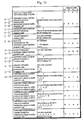
- Fig.13 shows how scheduling unit 18 determines an order of the instructions in the DAG shown in Fig.6B.
- the resource state information is provided.
- data registers D0, D1, and an address register AO are shown in the figure, and memories and flags are not shown.
- Fig.13 “candidates” item provides serial numbers of instruction nodes, "instruction selection” item a serial number of instruction node selected at step S3, "resource state” item the resource state at judgement of step 4, "output buffer” the order instruction nodes stored in output list buffer 17, “resource update” item the updated resource state after the instruction node is output to output list buffer 17, and "recursive call” item the number of times the recursive call is performed.
- Scheduling unit 18 is activated for the DAG of Fig.6B which is generated by DAG generating unit 15 and held by DAG holding unit 14. Since instruction nodes 1 and 4 are both top instruction nodes, having no link with parent instruction nodes (step t1), they are nominated for output candidates (step t3).
- Instruction node 4 receives rank 1 since a descendant instruction node has a hazard (step p5). Instruction node 1 receives rank 2 since no descendant instruction node has a hazard (step p4). As a result, instruction node 4 is selected as an output candidate because it has the highest rank 1 (step p6).
- Scheduling unit 18 refers to the resource state information to judge whether a resource defined by the selected instruction node is used (step S4). At this stage, since all the resources are "not used", instruction node 4 is output to output list buffer 17 (step S5). Then, scheduling unit 18 judges whether all the instruction nodes have been output to output list buffer 17 (step S6). At this stage, they have not been output. Therefore, the resource state information is updated, that is, register A0 defined by instruction node 4 is set to "used” (step S7). Then, the first recursive call is performed (step S8).
- instruction node 1 is a top instruction node, having no link with the parent instruction node (step t1), it is nominated for an output candidate (step t3).
- Instruction node 5 is also nominated for an output candidate since the parent instruction node 4 has been output (steps t2 and t3).
- Instruction node 5 receives rank 1 since a descendant instruction node has a hazard (step p5). Instruction node 1 receives rank 2 since no descendant instruction node has a hazard (step p4). As a result, instruction node 5 is selected as an output candidate because it has the highest rank 1 (step p6).
- Scheduling unit 18 refers to the resource state information to judge whether a resource defined by the selected instruction node is used (step S4). Since register D1 is "not used", instruction node 5 is output to output list buffer 17 (step S5). Then, since all the instruction nodes have not been output to output list buffer 17 (step S6), the resource state information is updated, that is, register A0 having had the last reference is set to "not used” (step S7). Then, the second recursive call is performed (step S8).
- Instruction node 1 is again nominated for an output candidate (step t3).
- Instruction node 6 is nominated for an output candidate since the parent instruction node 5 has been output (steps t2 and t3).
- Instruction node 6 receives rank 3 since a hazard exists between the instruction node and the parent instruction node 5, which is the latest output instruction node (step p3). Instruction node 1 receives rank 2 (step p4). As a result, instruction node 1 is selected as an output candidate because it has the highest rank (step p6).
- step S4 register D0 defined by instruction node 1 is "not used". Therefore, instruction node 1 is output to output list buffer 17 (step S5). Then, since all the instruction nodes have not been output to output list buffer 17 (step S6), the resource state information is updated, that is, register D0 is set to "used” (step S7). Then, the third recursive call is performed (step S8).
- Instruction nodes 2 and 6 are nominated for output candidates since the respective parent instruction nodes 1 and 5 have been output (steps t2 and t3).
- Instruction node 2 receives rank 2 since there is no hazard between the instruction node and the preceding output instruction node, nor has any descendant instruction node a hazard (step p4). Also, instruction node 6 receives rank 2 for the same reason (step p4). While either of instruction nodes 2 and 6 can be selected as an output candidate since they have the same rank, it is supposed that instruction node 6 is selected here (step p6).
- step S4 register D1 defined by instruction node 6 is "used" since it is defined by instruction node 5.
- instruction node 6 is the last reference of register D1 defined by instruction node 5 (step S11)
- instruction node 6 is output to output list buffer 17 (step S5).
- step S6 since all the instruction nodes have not been output to output list buffer 17 (step S6), the resource state information is updated, that is, register D1 defined by instruction node 6 is set to "used” (step S7).
- step S8 the fourth recursive call is performed.
- Instruction node 2 is nominated for an output candidate since the parent instruction node 1 has been output (steps t2 and t3).
- Instruction node 2 receives rank 2 since there is no hazard between the instruction node and the preceding output instruction node, nor has any descendant instruction node a hazard (step p4). Instruction node 2 is selected as an output candidate since there is no other candidate.
- step S4 register A0 defined by instruction node 2 is "not used”. Therefore, instruction node 2 is output to output list buffer 17 (step S5). Then, since all the instruction nodes have not been output to output list buffer 17 (step S6), the resource state information is updated, that is, register D0 of the last reference is set to "not used” (step S7). Then, the fifth recursive call is performed (step S8).
- Instruction node 3 is nominated for an output candidate since the parent instruction node 2 has been output (steps t2 and t3).
- Instruction node 3 receives rank 2 since there is no hazard between the instruction node and the preceding output instruction node, nor has any descendant instruction node a hazard (step p4). Instruction node 3 is selected as an output candidate since there is no other candidate.
- step S4 resource "mem” (not shown) defined by instruction node 3 is "not used”. Therefore, instruction node 3 is output to output list buffer 17 (step S5). Then, since all the instruction nodes of the basic block have been output to output list buffer 17, scheduling unit 18 returns to the start (steps S6 and S20).
- the instructions have been rearranged and stored in output list buffer 17 in order of 4-5-1-6-2-3, that is, in order of "MOV 20,A0”, “MOV (A0),D1” , “MOV 10,D0”, “ADD D1, D1” , “MOV D0,A0”, and “MOV 10,mem”.
- the underlined instructions were consecutive, having a hazard in between. They are separated now, and the hazard has been removed.
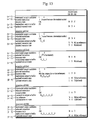
- Fig.14 shows how scheduling unit 18 determines an order of the instructions in the DAG shown in Fig.6C by using a back-track (return).
- the resource state information is provided on the right-hand side of the figure.
- data registers D0, D1, and D2 and an address register A0 are shown in the figure, and memories and flags are not shown.
- recursive call item provides a level of the number of times the recursive call is performed.
- Scheduling unit 18 is activated for the DAG of Fig.6C which is generated by DAG generating unit 15 and held by DAG holding unit 14. Since instruction node 4 is a top instruction node, having no link with the parent instruction node (step t1), it is nominated for an output candidate (step t3). On the other hand, though instruction node 1 has a link with the parent instruction node or with the start of the basic block, scheduling unit regards the parent instruction node as having been output, and nominates the instruction node 1 for an output candidate (steps t2 and t3).
- Instruction node 4 receives rank 1 since a descendant instruction node has a hazard (step p5). Instruction node 1 receives rank 2 since no descendant instruction node has a hazard (step p4). As a result, instruction node 4 is selected as an output candidate because it has the highest rank 1 (step p6).
- Scheduling unit 18 refers to the resource state information to judge whether a resource defined by the selected instruction node is used (step S4). Since a resource defined by instruction node 4 is "not used", instruction node 4 is output to output list buffer 17 (step S5). Since all the instruction nodes have not been output to output list buffer 7 (step S6), the resource state information is updated, that is, register D0 defined by instruction node 4 is set to "used” (step S7). Then, level-1 recursive call is performed (step S8).
- instruction node 1 is a top instruction node, having no link with the parent instruction node (step t1), it is nominated for an output candidate (step t3).
- Instruction node 5 is also nominated for an output candidate since the parent instruction node 4 has been output (steps t2 and t3).
- Instruction node 5 receives rank 1 since a descendant instruction node has a hazard (step p5). Instruction node 1 receives rank 2 since no descendant instruction node has a hazard (step p4). As a result, instruction node 5 is selected as an output candidate because it has the highest rank 1 (step p6).
- Scheduling unit 18 refers to the resource state information to judge whether a resource defined by the selected instruction node is used (step S4).
- register A0 defined by instruction node 5 is "used” ("S"), and instruction node 5 is not the last reference of register A0 for the definition indicated by "S”. Therefore, instruction node 5 is not output to output list buffer 17 (step S4, S11, and S12).
- instruction node 1 is selected as an output candidate (step 2).
- step S4 since register D0 defined by instruction node 1 is "used”, and instruction node 1 is not the last one to refer to register D0 for the definition indicated by "4" (step S4, S11, and S12), instruction node 1 is excluded from output candidates.
- scheduling unit 18 returns to step S9 with an "NG" return value (step S13).
- step S10 A former state when instruction node 4 has been output to output list buffer 17 and when instruction node 1 has been selected as an output candidate is resumed (step S10). Instruction node 4 stored in output list buffer 17 is canceled, and a former state when instruction node 4 has not been output is resumed (step 10). Then, scheduling unit 18 returns to step S2.
- Instruction node 1 receives rank 2 since no descendant instruction node has a hazard (step p4). Instruction node 1 is selected as an output candidate because there is no other candidate (step p6).
- step S5 Since register D0 defined by instruction node 1 is "not used", instruction node 1 is output to output list buffer 17 (step S5).
- the resource state information is updated, that is, register D0 defined by instruction node 1 is set to "used” (step S7), register A0 having had the last reference is returned to "not used”. Then, level-1 recursive call is performed (step S8).
- Instruction node 2 is nominated for an output candidate because the parent instruction node 1 has been output, and instruction node 4 is also nominated because it is a top node (steps t2 and t3).
- Instruction node 2 receives rank 2 since there is no hazard between the instruction node and the preceding output instruction node, nor has any descendant instruction node a hazard (step p4). On the other hand, instruction node 4 receives rank 1 since it has a hazard (step p5). As a result, instruction node 4 is selected as an output candidate (step p6).
- step S4 since instruction node 4 defines register DO, instruction node 4 is not output to output list buffer 17 (step S4, S11, and S12). Also, since instruction node 4 is not the last one to refer to register D0 defined by instruction node 1 (step S11), instruction node 4 is excluded from output candidates (step S12). Then, scheduling unit 18 returns to step S2.
- Scheduling unit 18 refers to the resource state information for the other output candidate, instruction node 2 (step S4). According to the reference result, instruction node 2 is output to output list buffer 17 (step S5). Since all the instruction nodes have not been output (step S6), register D0 having had the last reference is returned to "not used", and register D2 defined by instruction node 2 is set to "used” (step S7). Then, level-2 recursive call is performed (step S8).
- Instruction node 3 receives rank 2 since there is no hazard between the instruction node and the preceding output instruction node, nor has any descendant instruction node a hazard (step p4). Instruction node 4 receives rank 1 since a descendant instruction node has a hazard (step p5).
- the optimization apparatus of the present invention preserves dependence between instruction nodes with DAGs with only definition-reference links and resource state information taken from the last instruction stored in a buffer. As a result, there is more room for rearranging instructions. This increases the rate of removing hazards, assuring the generation of machine-language programs appropriate for pipeline processing.
- Second Embodiment partly modifies First Embodiment.
- step S11 of First Embodiment if it is judged that the selected instruction node is not the last reference, the instruction node is excluded from the candidates.
- Second Embodiment provides a chance for the instruction node to be output by replacing a resource in the instruction node by another resource.
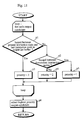
- Fig.15 shows steps S14, S15, and S16 are added to the flowchart of Fig.9.
- step S14 it is judged whether a resource defined by an instruction node can be replaced by another resource.
- the resource is also called a replacement object resource. If can, the replacement object resource is replaced by another resource at step S15. Then, all the same replacement object resources in a data-flow section for the resource are replaced by the resource at step S16. As for the data-flow section, see (b) below.
- step S14 the following three conditions are checked for a "replacing resource" in the judgement:
- MUL D1,D0 is a multiplication instruction with a function to multiply a value of D1 by that of D0.
- register A0 stores data with a format for memory access. Therefore, the processor does not succeed in executing instruction "MUL A0,D0.”
- types e.g. data register, address register, memory, etc.
- types of instructions which either define or refer to the resources and a type of the destructive instruction are identified.
- the types include indirect reference instruction, multiplication instruction, division instruction, etc.
- each combination of types of an instruction and a resource is compared with combination patterns stored in the processor, and resources in combinations that do not match the combination patterns are excluded from replacement-candidate resources.
- Fig.16 shows a DAG whose instruction nodes cannot be rearranged since a resource is always used.
- a hazard occurs between instructions 1 and 2 because register D0 defined by instruction 1 is referred to by instruction 2. Also, a hazard occurs between instructions 4 and 5 due to the same reason.
- Fig.17 shows replacements of resources defined by the instructions of the DAG as shown in Fig.16.
- step S14 it is judged whether the replacement object resource defined by instruction node 4 can be replaced by another resource. Since all the other resources are not used in the basic block, the above conditions (a) to (c) are satisfied. As a result, it is judged that register D0 is replaceable. At step 15, register D0 is replaced by register D1. Then, instruction node 2 "MOV mem_b, D0" is replaced by instruction node "MOV mem_b,D1" at step S16. Similarly, at step S16, all the other register D0s used in the descendant instruction nodes are replaced by register D1s.
- the optimization apparatus of Second Embodiment outputs instruction nodes by replacing resources in the instruction nodes by other resources maintaining dependence between instructions. As a result, there is more room for rearranging instructions. This increases the rate of removing hazards in pipeline processing.
- the optimization apparatus of the present invention deals with source programs written in an assembler language.
- the apparatus may be built in a compiler so that the apparatus operates on assembler programs with assembly codes output by the compiler.
Landscapes
- Engineering & Computer Science (AREA)
- General Engineering & Computer Science (AREA)
- Theoretical Computer Science (AREA)
- Software Systems (AREA)
- Physics & Mathematics (AREA)
- General Physics & Mathematics (AREA)
- Advance Control (AREA)
- Devices For Executing Special Programs (AREA)
- Storage Device Security (AREA)
- Document Processing Apparatus (AREA)
Applications Claiming Priority (3)
| Application Number | Priority Date | Filing Date | Title |
|---|---|---|---|
| JP10430095 | 1995-04-27 | ||
| JP07104300A JP3113792B2 (ja) | 1995-04-27 | 1995-04-27 | 最適化装置 |
| JP104300/95 | 1995-04-27 |
Publications (3)
| Publication Number | Publication Date |
|---|---|
| EP0740251A2 true EP0740251A2 (de) | 1996-10-30 |
| EP0740251A3 EP0740251A3 (de) | 1997-06-11 |
| EP0740251B1 EP0740251B1 (de) | 2002-07-10 |
Family
ID=14377080
Family Applications (1)
| Application Number | Title | Priority Date | Filing Date |
|---|---|---|---|
| EP96302868A Expired - Lifetime EP0740251B1 (de) | 1995-04-27 | 1996-04-24 | Optimierungsgerät zum Entfernen von Gefahren durch Arrangierung der Befehlsreihenfolge |
Country Status (7)
| Country | Link |
|---|---|
| US (1) | US5850552A (de) |
| EP (1) | EP0740251B1 (de) |
| JP (1) | JP3113792B2 (de) |
| KR (1) | KR100238330B1 (de) |
| CN (1) | CN1160627C (de) |
| DE (1) | DE69622219T2 (de) |
| TW (1) | TW352424B (de) |
Cited By (1)
| Publication number | Priority date | Publication date | Assignee | Title |
|---|---|---|---|---|
| CN110221838A (zh) * | 2019-05-28 | 2019-09-10 | 中国科学院高能物理研究所 | 一种基于遗传算法和有向无环图进行程序自动设计优化的方法 |
Families Citing this family (28)
| Publication number | Priority date | Publication date | Assignee | Title |
|---|---|---|---|---|
| USRE37093E1 (en) | 1991-06-03 | 2001-03-13 | Ricoh Company, Ltd. | Optical disk drive unit with a sealing type bearing member |
| US6044221A (en) * | 1997-05-09 | 2000-03-28 | Intel Corporation | Optimizing code based on resource sensitive hoisting and sinking |
| US5978588A (en) * | 1997-06-30 | 1999-11-02 | Sun Microsystems, Inc. | Method and apparatus for profile-based code placement using a minimum cut set of the control flow graph |
| JP3220055B2 (ja) * | 1997-07-17 | 2001-10-22 | 松下電器産業株式会社 | 機械語命令列またはアセンブリ言語命令列を最適化する最適化装置、及び、高級言語で記載されたソースプログラムを機械語またはアセンブリ言語の命令列に変換するコンパイラ装置。 |
| CN100347668C (zh) * | 1997-08-29 | 2007-11-07 | 松下电器产业株式会社 | 指令变换装置 |
| US6189141B1 (en) * | 1998-05-04 | 2001-02-13 | Hewlett-Packard Company | Control path evaluating trace designator with dynamically adjustable thresholds for activation of tracing for high (hot) activity and low (cold) activity of flow control |
| US6158049A (en) * | 1998-08-11 | 2000-12-05 | Compaq Computer Corporation | User transparent mechanism for profile feedback optimization |
| US6145125A (en) * | 1998-11-12 | 2000-11-07 | International Business Machines Corporation | Method and storage medium for building very large executable programs |
| US7058647B1 (en) | 1999-08-31 | 2006-06-06 | Charles E. Hill & Associates | Electronic presentation generation system and method |
| US6681387B1 (en) | 1999-12-01 | 2004-01-20 | Board Of Trustees Of The University Of Illinois | Method and apparatus for instruction execution hot spot detection and monitoring in a data processing unit |
| KR100304527B1 (ko) * | 2000-01-10 | 2001-11-03 | 이동욱, 이정호 | 현금카드를 통한 실시간 현금 결제 처리 방법 |
| US7433881B1 (en) | 2000-08-31 | 2008-10-07 | Charles E. Hill & Associates, Inc. | System and method for handling multi-resolution graphics files |
| US6675376B2 (en) * | 2000-12-29 | 2004-01-06 | Intel Corporation | System and method for fusing instructions |
| US7185327B2 (en) * | 2001-01-09 | 2007-02-27 | Hewlett-Packard Development Company, L.P. | System and method for optimizing operations via dataflow analysis |
| JP2002304823A (ja) * | 2001-04-10 | 2002-10-18 | Fujitsu Ltd | リオーダリングコントローラ、リオーダリング方法及び記憶装置 |
| US7000095B2 (en) * | 2002-09-06 | 2006-02-14 | Mips Technologies, Inc. | Method and apparatus for clearing hazards using jump instructions |
| US7448030B2 (en) * | 2004-03-18 | 2008-11-04 | Intel Corporation | Optimized ordering of firmware modules in pre-boot environment |
| US7506331B2 (en) * | 2004-08-30 | 2009-03-17 | International Business Machines Corporation | Method and apparatus for determining the profitability of expanding unpipelined instructions |
| CN100590592C (zh) * | 2005-01-13 | 2010-02-17 | Nxp股份有限公司 | 处理器及其指令发布方法 |
| US7908163B2 (en) * | 2005-07-15 | 2011-03-15 | The Board Of Trustees Of The University Of Alabama | Method and system for parallel scheduling of complex dags under uncertainty |
| US7330962B2 (en) * | 2005-11-14 | 2008-02-12 | Nvidia Corporation | Dynamic instruction sequence selection during scheduling |
| US8539467B2 (en) * | 2006-07-27 | 2013-09-17 | International Business Machines Corporation | Method and data processing system for solving resource conflicts in assembler programs |
| TWI334571B (en) * | 2007-02-16 | 2010-12-11 | Via Tech Inc | Program instruction rearrangement methods |
| US8612944B2 (en) * | 2008-04-17 | 2013-12-17 | Qualcomm Incorporated | Code evaluation for in-order processing |
| US9690591B2 (en) * | 2008-10-30 | 2017-06-27 | Intel Corporation | System and method for fusing instructions queued during a time window defined by a delay counter |
| JP5140105B2 (ja) * | 2010-03-23 | 2013-02-06 | Necシステムテクノロジー株式会社 | 命令スケジューリング装置、命令スケジューリング方法および命令スケジューリングプログラム |
| CN106959957B (zh) * | 2016-01-11 | 2020-07-07 | 阿里巴巴集团控股有限公司 | 一种有向无环图dag连线提示方法及装置 |
| JP6325625B2 (ja) * | 2016-10-14 | 2018-05-16 | ファナック株式会社 | プログラム最適化システム |
Family Cites Families (6)
| Publication number | Priority date | Publication date | Assignee | Title |
|---|---|---|---|---|
| US5161216A (en) * | 1989-03-08 | 1992-11-03 | Wisconsin Alumni Research Foundation | Interprocedural slicing of computer programs using dependence graphs |
| JPH03135630A (ja) * | 1989-10-20 | 1991-06-10 | Nec Corp | 命令スケジューリング方式 |
| US5119495A (en) * | 1989-12-21 | 1992-06-02 | Bull Hn Information Systems Inc. | Minimizing hardware pipeline breaks using software scheduling techniques during compilation |
| US5107418A (en) * | 1990-06-11 | 1992-04-21 | Supercomputer Systems Limited Partnership | Method for representing scalar data dependences for an optimizing compiler |
| US5202993A (en) * | 1991-02-27 | 1993-04-13 | Sun Microsystems, Inc. | Method and apparatus for cost-based heuristic instruction scheduling |
| US5448737A (en) * | 1992-03-17 | 1995-09-05 | International Business Machines Corporation | System and method for optimizing computer code using a compact data flow representation |
-
1995
- 1995-04-27 JP JP07104300A patent/JP3113792B2/ja not_active Expired - Lifetime
-
1996
- 1996-04-08 TW TW085104068A patent/TW352424B/zh active
- 1996-04-08 US US08/628,904 patent/US5850552A/en not_active Expired - Lifetime
- 1996-04-24 DE DE69622219T patent/DE69622219T2/de not_active Expired - Fee Related
- 1996-04-24 EP EP96302868A patent/EP0740251B1/de not_active Expired - Lifetime
- 1996-04-26 KR KR1019960013068A patent/KR100238330B1/ko not_active Expired - Fee Related
- 1996-04-27 CN CNB961084553A patent/CN1160627C/zh not_active Expired - Fee Related
Cited By (1)
| Publication number | Priority date | Publication date | Assignee | Title |
|---|---|---|---|---|
| CN110221838A (zh) * | 2019-05-28 | 2019-09-10 | 中国科学院高能物理研究所 | 一种基于遗传算法和有向无环图进行程序自动设计优化的方法 |
Also Published As
| Publication number | Publication date |
|---|---|
| JPH08305577A (ja) | 1996-11-22 |
| CN1146577A (zh) | 1997-04-02 |
| DE69622219T2 (de) | 2002-10-31 |
| EP0740251A3 (de) | 1997-06-11 |
| KR100238330B1 (ko) | 2000-01-15 |
| US5850552A (en) | 1998-12-15 |
| TW352424B (en) | 1999-02-11 |
| EP0740251B1 (de) | 2002-07-10 |
| JP3113792B2 (ja) | 2000-12-04 |
| KR960038647A (ko) | 1996-11-21 |
| CN1160627C (zh) | 2004-08-04 |
| DE69622219D1 (de) | 2002-08-14 |
Similar Documents
| Publication | Publication Date | Title |
|---|---|---|
| US5850552A (en) | Optimization apparatus for removing hazards by arranging instruction order | |
| Gamrath et al. | The SCIP optimization suite 7.0 | |
| US5604908A (en) | Computer program product for using build status indicators in connection with building of complex computer programs from source code parts | |
| US5712996A (en) | Process for dividing instructions of a computer program into instruction groups for parallel processing | |
| US7533375B2 (en) | Program parallelization device, program parallelization method, and program parallelization program | |
| US6243864B1 (en) | Compiler for optimizing memory instruction sequences by marking instructions not having multiple memory address paths | |
| US7120904B1 (en) | Data-flow method for optimizing exception-handling instructions in programs | |
| US7010787B2 (en) | Branch instruction conversion to multi-threaded parallel instructions | |
| US5828886A (en) | Compiling apparatus and method for promoting an optimization effect of a program | |
| EP0899656B1 (de) | Programmkonvertiergerät für konstantenrekonstruierenden VLIW Prozessor | |
| US5894576A (en) | Method and apparatus for instruction scheduling to reduce negative effects of compensation code | |
| US20040083468A1 (en) | Instruction scheduling method, instruction scheduling device, and instruction scheduling program | |
| US6298479B1 (en) | Method and system for compiling and linking source files | |
| US9582321B2 (en) | System and method of data processing | |
| US20090313600A1 (en) | Concurrent code generation | |
| US6675380B1 (en) | Path speculating instruction scheduler | |
| US5367683A (en) | Smart recompilation of performing matchup/difference after code generation | |
| US20020035722A1 (en) | Interactive instruction scheduling and block ordering | |
| EP0749067A2 (de) | Optimierer | |
| JP3179536B2 (ja) | ディジタルコンピュータの操作方法 | |
| US7069555B1 (en) | Super-region instruction scheduling and code generation for merging identical instruction into the ready-to-schedule instruction | |
| US6564372B1 (en) | Critical path optimization-unzipping | |
| US5535392A (en) | Using hint generation to cause portions of object files to remain the same | |
| US5276821A (en) | Operation assignment method and apparatus therefor | |
| JP3311381B2 (ja) | コンパイラにおける命令スケジューリング処理方法 |
Legal Events
| Date | Code | Title | Description |
|---|---|---|---|
| PUAI | Public reference made under article 153(3) epc to a published international application that has entered the european phase |
Free format text: ORIGINAL CODE: 0009012 |
|
| AK | Designated contracting states |
Kind code of ref document: A2 Designated state(s): DE FR GB NL |
|
| PUAL | Search report despatched |
Free format text: ORIGINAL CODE: 0009013 |
|
| AK | Designated contracting states |
Kind code of ref document: A3 Designated state(s): DE FR GB NL |
|
| 17P | Request for examination filed |
Effective date: 19970707 |
|
| 17Q | First examination report despatched |
Effective date: 20000320 |
|
| GRAG | Despatch of communication of intention to grant |
Free format text: ORIGINAL CODE: EPIDOS AGRA |
|
| GRAG | Despatch of communication of intention to grant |
Free format text: ORIGINAL CODE: EPIDOS AGRA |
|
| GRAG | Despatch of communication of intention to grant |
Free format text: ORIGINAL CODE: EPIDOS AGRA |
|
| GRAH | Despatch of communication of intention to grant a patent |
Free format text: ORIGINAL CODE: EPIDOS IGRA |
|
| GRAH | Despatch of communication of intention to grant a patent |
Free format text: ORIGINAL CODE: EPIDOS IGRA |
|
| GRAA | (expected) grant |
Free format text: ORIGINAL CODE: 0009210 |
|
| AK | Designated contracting states |
Kind code of ref document: B1 Designated state(s): DE FR GB NL |
|
| REG | Reference to a national code |
Ref country code: GB Ref legal event code: FG4D |
|
| REF | Corresponds to: |
Ref document number: 69622219 Country of ref document: DE Date of ref document: 20020814 |
|
| ET | Fr: translation filed | ||
| PLBE | No opposition filed within time limit |
Free format text: ORIGINAL CODE: 0009261 |
|
| STAA | Information on the status of an ep patent application or granted ep patent |
Free format text: STATUS: NO OPPOSITION FILED WITHIN TIME LIMIT |
|
| 26N | No opposition filed |
Effective date: 20030411 |
|
| PGFP | Annual fee paid to national office [announced via postgrant information from national office to epo] |
Ref country code: NL Payment date: 20090427 Year of fee payment: 14 Ref country code: FR Payment date: 20090417 Year of fee payment: 14 Ref country code: DE Payment date: 20090420 Year of fee payment: 14 |
|
| PGFP | Annual fee paid to national office [announced via postgrant information from national office to epo] |
Ref country code: GB Payment date: 20090422 Year of fee payment: 14 |
|
| REG | Reference to a national code |
Ref country code: NL Ref legal event code: V1 Effective date: 20101101 |
|
| GBPC | Gb: european patent ceased through non-payment of renewal fee |
Effective date: 20100424 |
|
| REG | Reference to a national code |
Ref country code: FR Ref legal event code: ST Effective date: 20101230 |
|
| PG25 | Lapsed in a contracting state [announced via postgrant information from national office to epo] |
Ref country code: NL Free format text: LAPSE BECAUSE OF NON-PAYMENT OF DUE FEES Effective date: 20101101 |
|
| PG25 | Lapsed in a contracting state [announced via postgrant information from national office to epo] |
Ref country code: DE Free format text: LAPSE BECAUSE OF NON-PAYMENT OF DUE FEES Effective date: 20101103 |
|
| PG25 | Lapsed in a contracting state [announced via postgrant information from national office to epo] |
Ref country code: GB Free format text: LAPSE BECAUSE OF NON-PAYMENT OF DUE FEES Effective date: 20100424 |
|
| PG25 | Lapsed in a contracting state [announced via postgrant information from national office to epo] |
Ref country code: FR Free format text: LAPSE BECAUSE OF NON-PAYMENT OF DUE FEES Effective date: 20100430 |