EP0740318A2 - Transformateur à haute tension pour un récepteur de télévision - Google Patents
Transformateur à haute tension pour un récepteur de télévision Download PDFInfo
- Publication number
- EP0740318A2 EP0740318A2 EP96106154A EP96106154A EP0740318A2 EP 0740318 A2 EP0740318 A2 EP 0740318A2 EP 96106154 A EP96106154 A EP 96106154A EP 96106154 A EP96106154 A EP 96106154A EP 0740318 A2 EP0740318 A2 EP 0740318A2
- Authority
- EP
- European Patent Office
- Prior art keywords
- core
- leg
- legs
- core leg
- chamfer
- Prior art date
- Legal status (The legal status is an assumption and is not a legal conclusion. Google has not performed a legal analysis and makes no representation as to the accuracy of the status listed.)
- Granted
Links
Images
Classifications
-
- H—ELECTRICITY
- H01—ELECTRIC ELEMENTS
- H01F—MAGNETS; INDUCTANCES; TRANSFORMERS; SELECTION OF MATERIALS FOR THEIR MAGNETIC PROPERTIES
- H01F3/00—Cores, Yokes, or armatures
- H01F3/10—Composite arrangements of magnetic circuits
- H01F3/14—Constrictions; Gaps, e.g. air-gaps
-
- H—ELECTRICITY
- H01—ELECTRIC ELEMENTS
- H01F—MAGNETS; INDUCTANCES; TRANSFORMERS; SELECTION OF MATERIALS FOR THEIR MAGNETIC PROPERTIES
- H01F38/00—Adaptations of transformers or inductances for specific applications or functions
- H01F38/42—Flyback transformers
-
- H—ELECTRICITY
- H01—ELECTRIC ELEMENTS
- H01F—MAGNETS; INDUCTANCES; TRANSFORMERS; SELECTION OF MATERIALS FOR THEIR MAGNETIC PROPERTIES
- H01F5/00—Coils
- H01F5/02—Coils wound on non-magnetic supports, e.g. formers
- H01F2005/022—Coils wound on non-magnetic supports, e.g. formers wound on formers with several winding chambers separated by flanges, e.g. for high voltage applications
Definitions
- the invention is based on a high-voltage transformer according to the preamble of claim 1.
- a transformer is known from DE-OS 43 02 271.
- a wedge-shaped air gap is created between the ends of the core legs colliding, which advantageously influences the magnetization characteristic of the transformer.
- the two legs meet e.g. together on the outer edge of the core.
- the contact surface is punctiform or linear and therefore very small. This small area results in a high system pressure. Due to tolerance-related deviations in the geometric position of the two core legs relative to one another and in the dimensions of the core legs, it can therefore happen that the outer edges of the two core legs match exactly and then the risk of an edge breaking out on the outside of a core leg is particularly great.
- the invention has for its object to modify the core so that the two core legs are properly supported even with tolerances and the risk of core parts breaking out is reduced.
- the end of a core leg is thus chamfered or rounded on the outside such that the contact area between the core legs is removed from the outer edges of the core legs.
- the contact area in which the two ends of the two legs meet is moved from the outer edge of the core legs towards the center of the core legs. If tolerances now occur in the position of this area, there is no longer any risk that the Contact area with the edges of the core legs.
- the contact area, which is in particular punctiform or line-shaped, is thus with certainty for a core always in an area of the front end of the core leg that is far enough from the edge. The risk of breakage is thus eliminated for this core.
- the edge of one core leg, with which it rests on the front end of the other core leg forms an angle of 90 ° and is therefore relatively sharp.
- the edge at the end of one core leg, which meets the front end of the other core leg forms an increased angle of the order of 130-150 ° and is therefore less sharp, which reduces the risk of damage to this core leg becomes.
- the invention is applicable to core legs with a round and rectangular cross section.
- the end of the core leg is preferably provided with a chamfer. Such a chamfer can be produced when the core is pressed without any significant additional effort.
- the chamfer preferably forms an angle of the order of 130 ° with the front end of the core leg and extends e.g. over about 10% of the width or diameter of the core leg.
- the core leg is preferably symmetrically chamfered or rounded on opposite edges in the same way. This can simplify production and, in particular, avoid stresses during sintering of the core.
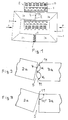
- Fig. 1 shows a ferrite core 1 with two U-shaped core halves 2, 3 whose parallel legs 2a, 2b and 3a, 3b are each composed. This results in a first joint between the core legs 2a and 3a and a second joint between the core legs 2b and 3b.
- the two core halves 2, 3 are tilted against each other. This results in a wedge-shaped air gap 5 at the upper joint, which causes the described improvement in the magnetization characteristic of the transformer and the reduction in the internal resistance of the high-voltage source.
- the core legs 2a and 3a carry the coil former 8, which carries the primary winding 9 and the high-voltage winding 10 designed as a chamber winding.
- the front end of the core leg 3a is now provided with a bevel in the form of a chamfer 11, which forms an angle ⁇ of approximately 130 ° with the remaining surface area of the front end of the core leg 3a.
- a chamfer 11 which forms an angle ⁇ of approximately 130 ° with the remaining surface area of the front end of the core leg 3a.
- the joint 4 which would in itself lie on the upper edge of the core legs 2a and 3a, is displaced in the direction of the center of the core legs 2a, 3a.
- the joint 4 is now so far from the edge of the Core leg 2a and 3a removed that the edge at the end of the core leg 3a rests much more prone to breakage on the end face of the core leg 2a.
- Fig. 2 shows the formation of the core legs 2a and 3a somewhat enlarged. It can be seen that the angle ⁇ between the chamfer 11 and the rest of the front end of the core leg 3a is substantially greater than 90 °, namely approximately 130-150 °. This increased angle reduces the risk of the core being destroyed or individual core parts breaking out. For manufacturing reasons, the chamfer 11 is also provided symmetrically on the other edge of the core leg 3a.
- Fig. 3 shows a known arrangement of the mutually tilted core legs 2a, 3a. This results in the dangerous punctiform or linear support 11 between two sharp edges, in which the risk of breaking out of ferrite parts is very high.
Landscapes
- Engineering & Computer Science (AREA)
- Power Engineering (AREA)
- Chemical & Material Sciences (AREA)
- Composite Materials (AREA)
- Coils Or Transformers For Communication (AREA)
Applications Claiming Priority (2)
| Application Number | Priority Date | Filing Date | Title |
|---|---|---|---|
| DE19515226 | 1995-04-28 | ||
| DE19515226A DE19515226A1 (de) | 1995-04-28 | 1995-04-28 | Hochspannungstransformator für einen Fernsehempfänger |
Publications (3)
| Publication Number | Publication Date |
|---|---|
| EP0740318A2 true EP0740318A2 (fr) | 1996-10-30 |
| EP0740318A3 EP0740318A3 (fr) | 1997-06-04 |
| EP0740318B1 EP0740318B1 (fr) | 1999-05-26 |
Family
ID=7760343
Family Applications (1)
| Application Number | Title | Priority Date | Filing Date |
|---|---|---|---|
| EP96106154A Expired - Lifetime EP0740318B1 (fr) | 1995-04-28 | 1996-04-19 | Transformateur à haute tension pour un récepteur de télévision |
Country Status (4)
| Country | Link |
|---|---|
| US (1) | US5754087A (fr) |
| EP (1) | EP0740318B1 (fr) |
| JP (1) | JP3545128B2 (fr) |
| DE (2) | DE19515226A1 (fr) |
Families Citing this family (6)
| Publication number | Priority date | Publication date | Assignee | Title |
|---|---|---|---|---|
| DE19545304A1 (de) * | 1995-12-05 | 1997-06-12 | Bosch Gmbh Robert | Transformator mit aufgeteilter Primärwicklung in einer Sperrwandler-Versorgungsschaltung |
| AU2001260837A1 (en) * | 2000-05-11 | 2001-11-20 | Canterbury TX Limited | Partial core, low frequency transformer |
| JP4775254B2 (ja) * | 2006-12-26 | 2011-09-21 | トヨタ自動車株式会社 | リアクトルコアおよびリアクトル |
| WO2016049316A1 (fr) * | 2014-09-24 | 2016-03-31 | Hiq Solar, Inc. | Nouvelle construction de bobine d'induction à double entrefer |
| CN106716563A (zh) * | 2014-09-24 | 2017-05-24 | Hiq太阳能股份有限公司 | 双间隙感应器的新颖构造 |
| US20170194091A1 (en) * | 2016-01-05 | 2017-07-06 | The Boeing Company | Saturation resistant electromagnetic device |
Family Cites Families (4)
| Publication number | Priority date | Publication date | Assignee | Title |
|---|---|---|---|---|
| DE2753709A1 (de) * | 1977-12-02 | 1979-06-07 | Blum Eisen & Metallind | Aus blechen zu bildendes paket fuer elektrische maschinen, wie transformatoren, drosselspulen, zuendspulen, elektromotore, generatoren o.dgl. |
| DE3017368A1 (de) * | 1980-05-07 | 1981-11-12 | Licentia Patent-Verwaltungs-Gmbh, 6000 Frankfurt | Zeilentransformator fuer einen fernsehempfaenger |
| DE8428108U1 (de) * | 1984-09-24 | 1985-01-03 | Siemens AG, 1000 Berlin und 8000 München | Speicherdrossel |
| DE4302271A1 (de) * | 1993-01-28 | 1994-08-04 | Thomson Brandt Gmbh | Hochspannungstransformator für einen Fernsehempfänger |
-
1995
- 1995-04-28 DE DE19515226A patent/DE19515226A1/de not_active Withdrawn
-
1996
- 1996-03-27 US US08/622,915 patent/US5754087A/en not_active Expired - Lifetime
- 1996-04-19 EP EP96106154A patent/EP0740318B1/fr not_active Expired - Lifetime
- 1996-04-19 DE DE59601975T patent/DE59601975D1/de not_active Expired - Fee Related
- 1996-04-25 JP JP10555796A patent/JP3545128B2/ja not_active Expired - Fee Related
Also Published As
| Publication number | Publication date |
|---|---|
| US5754087A (en) | 1998-05-19 |
| EP0740318B1 (fr) | 1999-05-26 |
| DE59601975D1 (de) | 1999-07-01 |
| JP3545128B2 (ja) | 2004-07-21 |
| DE19515226A1 (de) | 1996-11-07 |
| EP0740318A3 (fr) | 1997-06-04 |
| JPH0945565A (ja) | 1997-02-14 |
Similar Documents
| Publication | Publication Date | Title |
|---|---|---|
| DE69105673T2 (de) | Transformator. | |
| EP0793243B1 (fr) | Transformateur | |
| EP0740318B1 (fr) | Transformateur à haute tension pour un récepteur de télévision | |
| EP0024319B1 (fr) | Procédé de fabrication de tôles de noyau en E et de tôles de culasse en I d'une bobine d'induction ou d'un transformateur, en particulier pour des lampes à décharge gazeuse | |
| DE69728709T2 (de) | Vakuum-lastschalter oder-leistungsschalter | |
| DE4219806C2 (de) | Filtersteckverbinder | |
| EP0226907A2 (fr) | Relais | |
| EP0176607A1 (fr) | Dispositif de liaison électrique au bout d'un bobinage | |
| DE2647203C3 (de) | Elektromagnetisches Miniaturrelais | |
| DE3413740A1 (de) | Schraubklemme | |
| EP0100922A1 (fr) | Moitié d'un dispositif de connexion multipolaire | |
| DE1588160C3 (de) | Überspannungsschutzvorrichtung | |
| DE3637626C2 (de) | Verfahren zum Festlegen eines Metallstifts innerhalb eines keramischen Isolierkörpers | |
| EP0069973B1 (fr) | Bobine de transformateur | |
| DE10127556A1 (de) | Metallischer Draht | |
| DE1942643A1 (de) | Klemmelement zum loetfreien Anschluss isolierter elektrischer Leiter | |
| EP0152096B1 (fr) | Ballast inductif pour lampes à décharge | |
| DE1234876B (de) | Elektromagnetische Verzoegerungsstrecke in Form einer Kunstleitung | |
| DE4302271A1 (de) | Hochspannungstransformator für einen Fernsehempfänger | |
| EP0776064A2 (fr) | Contact de soudage, en particulier pour une application dans un corps de bobine | |
| DE3611069A1 (de) | Vorschaltdrossel, insbesondere fuer gasentladungslampen | |
| DE9213889U1 (de) | Spule für ein elektromagnetisches Relais | |
| DE4132699C2 (de) | Mehrfachzündspule | |
| DE2150890A1 (de) | Vorschaltdrossel fuer leuchtstofflampen | |
| DE2745984C2 (de) | Drehschalter |
Legal Events
| Date | Code | Title | Description |
|---|---|---|---|
| PUAI | Public reference made under article 153(3) epc to a published international application that has entered the european phase |
Free format text: ORIGINAL CODE: 0009012 |
|
| AK | Designated contracting states |
Kind code of ref document: A2 Designated state(s): DE FR GB IT |
|
| PUAL | Search report despatched |
Free format text: ORIGINAL CODE: 0009013 |
|
| AK | Designated contracting states |
Kind code of ref document: A3 Designated state(s): DE FR GB IT |
|
| 17P | Request for examination filed |
Effective date: 19971031 |
|
| 17Q | First examination report despatched |
Effective date: 19980129 |
|
| GRAG | Despatch of communication of intention to grant |
Free format text: ORIGINAL CODE: EPIDOS AGRA |
|
| GRAG | Despatch of communication of intention to grant |
Free format text: ORIGINAL CODE: EPIDOS AGRA |
|
| GRAH | Despatch of communication of intention to grant a patent |
Free format text: ORIGINAL CODE: EPIDOS IGRA |
|
| GRAH | Despatch of communication of intention to grant a patent |
Free format text: ORIGINAL CODE: EPIDOS IGRA |
|
| GRAA | (expected) grant |
Free format text: ORIGINAL CODE: 0009210 |
|
| ITF | It: translation for a ep patent filed | ||
| AK | Designated contracting states |
Kind code of ref document: B1 Designated state(s): DE FR GB IT |
|
| GBT | Gb: translation of ep patent filed (gb section 77(6)(a)/1977) |
Effective date: 19990526 |
|
| ET | Fr: translation filed | ||
| REF | Corresponds to: |
Ref document number: 59601975 Country of ref document: DE Date of ref document: 19990701 |
|
| PLBE | No opposition filed within time limit |
Free format text: ORIGINAL CODE: 0009261 |
|
| STAA | Information on the status of an ep patent application or granted ep patent |
Free format text: STATUS: NO OPPOSITION FILED WITHIN TIME LIMIT |
|
| 26N | No opposition filed | ||
| REG | Reference to a national code |
Ref country code: GB Ref legal event code: 746 Effective date: 20010808 |
|
| REG | Reference to a national code |
Ref country code: FR Ref legal event code: D6 |
|
| REG | Reference to a national code |
Ref country code: GB Ref legal event code: IF02 |
|
| PGFP | Annual fee paid to national office [announced via postgrant information from national office to epo] |
Ref country code: DE Payment date: 20070424 Year of fee payment: 12 |
|
| PGFP | Annual fee paid to national office [announced via postgrant information from national office to epo] |
Ref country code: FR Payment date: 20070424 Year of fee payment: 12 |
|
| PGFP | Annual fee paid to national office [announced via postgrant information from national office to epo] |
Ref country code: GB Payment date: 20080326 Year of fee payment: 13 |
|
| PGFP | Annual fee paid to national office [announced via postgrant information from national office to epo] |
Ref country code: IT Payment date: 20080424 Year of fee payment: 13 |
|
| PG25 | Lapsed in a contracting state [announced via postgrant information from national office to epo] |
Ref country code: DE Free format text: LAPSE BECAUSE OF NON-PAYMENT OF DUE FEES Effective date: 20081101 |
|
| REG | Reference to a national code |
Ref country code: FR Ref legal event code: ST Effective date: 20081231 |
|
| PG25 | Lapsed in a contracting state [announced via postgrant information from national office to epo] |
Ref country code: FR Free format text: LAPSE BECAUSE OF NON-PAYMENT OF DUE FEES Effective date: 20080430 |
|
| GBPC | Gb: european patent ceased through non-payment of renewal fee |
Effective date: 20090419 |
|
| PG25 | Lapsed in a contracting state [announced via postgrant information from national office to epo] |
Ref country code: GB Free format text: LAPSE BECAUSE OF NON-PAYMENT OF DUE FEES Effective date: 20090419 |
|
| PG25 | Lapsed in a contracting state [announced via postgrant information from national office to epo] |
Ref country code: IT Free format text: LAPSE BECAUSE OF NON-PAYMENT OF DUE FEES Effective date: 20090419 |