EP0740374A2 - Kontakhalterungssystem - Google Patents
Kontakhalterungssystem Download PDFInfo
- Publication number
- EP0740374A2 EP0740374A2 EP96301955A EP96301955A EP0740374A2 EP 0740374 A2 EP0740374 A2 EP 0740374A2 EP 96301955 A EP96301955 A EP 96301955A EP 96301955 A EP96301955 A EP 96301955A EP 0740374 A2 EP0740374 A2 EP 0740374A2
- Authority
- EP
- European Patent Office
- Prior art keywords
- contact
- passageway
- latch
- housing
- body portion
- Prior art date
- Legal status (The legal status is an assumption and is not a legal conclusion. Google has not performed a legal analysis and makes no representation as to the accuracy of the status listed.)
- Granted
Links
- 230000014759 maintenance of location Effects 0.000 title claims abstract description 15
- 238000003780 insertion Methods 0.000 claims abstract description 14
- 230000037431 insertion Effects 0.000 claims abstract description 14
- 238000004519 manufacturing process Methods 0.000 description 5
- 230000013011 mating Effects 0.000 description 4
- 230000004888 barrier function Effects 0.000 description 3
- 239000002184 metal Substances 0.000 description 3
- 229910052751 metal Inorganic materials 0.000 description 3
- 239000000463 material Substances 0.000 description 2
- 229910000906 Bronze Inorganic materials 0.000 description 1
- OAICVXFJPJFONN-UHFFFAOYSA-N Phosphorus Chemical compound [P] OAICVXFJPJFONN-UHFFFAOYSA-N 0.000 description 1
- 238000013459 approach Methods 0.000 description 1
- 239000010974 bronze Substances 0.000 description 1
- KUNSUQLRTQLHQQ-UHFFFAOYSA-N copper tin Chemical compound [Cu].[Sn] KUNSUQLRTQLHQQ-UHFFFAOYSA-N 0.000 description 1
- 239000003989 dielectric material Substances 0.000 description 1
- 150000002739 metals Chemical class 0.000 description 1
- 238000000034 method Methods 0.000 description 1
- 229920000728 polyester Polymers 0.000 description 1
- 230000036316 preload Effects 0.000 description 1
- 230000000717 retained effect Effects 0.000 description 1
Images


Classifications
-
- H—ELECTRICITY
- H01—ELECTRIC ELEMENTS
- H01R—ELECTRICALLY-CONDUCTIVE CONNECTIONS; STRUCTURAL ASSOCIATIONS OF A PLURALITY OF MUTUALLY-INSULATED ELECTRICAL CONNECTING ELEMENTS; COUPLING DEVICES; CURRENT COLLECTORS
- H01R13/00—Details of coupling devices of the kinds covered by groups H01R12/70 or H01R24/00 - H01R33/00
- H01R13/40—Securing contact members in or to a base or case; Insulating of contact members
-
- H—ELECTRICITY
- H01—ELECTRIC ELEMENTS
- H01R—ELECTRICALLY-CONDUCTIVE CONNECTIONS; STRUCTURAL ASSOCIATIONS OF A PLURALITY OF MUTUALLY-INSULATED ELECTRICAL CONNECTING ELEMENTS; COUPLING DEVICES; CURRENT COLLECTORS
- H01R43/00—Apparatus or processes specially adapted for manufacturing, assembling, maintaining, or repairing of line connectors or current collectors or for joining electric conductors
- H01R43/20—Apparatus or processes specially adapted for manufacturing, assembling, maintaining, or repairing of line connectors or current collectors or for joining electric conductors for assembling or disassembling contact members with insulating base, case or sleeve
-
- H—ELECTRICITY
- H01—ELECTRIC ELEMENTS
- H01R—ELECTRICALLY-CONDUCTIVE CONNECTIONS; STRUCTURAL ASSOCIATIONS OF A PLURALITY OF MUTUALLY-INSULATED ELECTRICAL CONNECTING ELEMENTS; COUPLING DEVICES; CURRENT COLLECTORS
- H01R12/00—Structural associations of a plurality of mutually-insulated electrical connecting elements, specially adapted for printed circuits, e.g. printed circuit boards [PCB], flat or ribbon cables, or like generally planar structures, e.g. terminal strips, terminal blocks; Coupling devices specially adapted for printed circuits, flat or ribbon cables, or like generally planar structures; Terminals specially adapted for contact with, or insertion into, printed circuits, flat or ribbon cables, or like generally planar structures
- H01R12/70—Coupling devices
- H01R12/71—Coupling devices for rigid printing circuits or like structures
- H01R12/72—Coupling devices for rigid printing circuits or like structures coupling with the edge of the rigid printed circuits or like structures
- H01R12/721—Coupling devices for rigid printing circuits or like structures coupling with the edge of the rigid printed circuits or like structures cooperating directly with the edge of the rigid printed circuits
Definitions
- the present invention relates to electrical connectors and more particularly to a contact retention system for electrical connectors.
- the various ways of retaining the contacts include providing an interference fit within contact receiving passageways of a housing, using outwardly projecting lances on the contacts which abut an internal surface within the passageway or use of a secondary step in manufacturing, such as staking, use of a tool and a high force latch or the like.
- a secondary step in manufacturing such as staking, use of a tool and a high force latch or the like.
- a contact retention system using a self-seating contact includes a housing having at least one contact receiving passageway extending from an assembly face to a connecting face and a contact associated with the passageway, and insertable into the passageway from the assembly face.
- the contact has a selected thickness, opposed side surfaces and opposed edges, and leading and trailing end portions of selected widths.
- the leading end includes a connecting section.
- the contact further has a body portion intermediate the leading and trailing end portions to be disposed along a portion of the passageway upon full contact insertion.
- the contact body portion has a dimension wider than the leading and trailing end portions.
- a section of the contact body portion extends laterally outwardly from at least one edge of the contact and defines at least one forwardly facing latch surface and at least one rearwardly facing latch surface.
- the housing passageway portion includes first and second opposed side surfaces associated with the side surfaces of the contact.
- a first passageway side surface has at least one first latching projection extending toward a second passageway side surface and defines a forwardly facing stop surface associated with the rearwardly facing latch surface on the contact.
- the second passageway side surface has at least one second latch projection extending toward the first passageway side surface and defines a rearwardly facing stop surface associated with the forward facing latch surface of the contact.
- the first and second latch projections are offset from the edges of trailing and leading end portions of the contact and axially spaced from each other a distance slightly greater than the length of the body portion.
- the housing includes a biasing surface proximate the assembly face and opposed from the first passageway side surface, and the contact includes a biasing portion along the trailing end portion engageable with the biasing surface prior to full contact insertion.
- the biasing surface urges the body portion against the first projection along the first passageway side surface until the body portion passes the projection.
- the leading end encounters the first latching projection so that the trailing end of the contact is constrained to urge the contact against the first latching projection until full insertion thereafter the latch seats.
- the wide body portion is thereby disposed between the two latch projections upon being seated in the housing and is self latching in the passageway portion.
- the body portion has a section thereof that extends outwardly from both side edges of the contact defining two forwardly facing latch surfaces and two rearwardly facing latch surfaces.
- the passageway in the housing includes two rearwardly and two forwardly facing stop surfaces that engage the respective latch surfaces on the contact.
- the second latch projection is spaced from side surface a distance less that the thickness of the contact and defines a constriction along the connecting face.
- the contact retention system of the present invention has a relatively low insertion force thereby allowing multiple contacts, such as in a strip of contacts, to be inserted in the housing simultaneously.
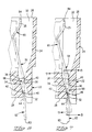
- FIGURE 1 is a cross sectional view of an electrical connector having the contact retention system of the present invention.
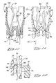
- FIGURE 2 is a isometric view of the contact used in the connector of Figure 1.
- FIGURE 3 is a enlarged fragmentary sectional view of the contact passageway portion with the contact removed there from.
- FIGURES 4 through 7 illustrate the sequential insertion of the contact of Figure 2 into the connector of Figure 1 with the contact in Figure 7 being shown fully inserted.
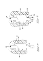
- FIGURE 8 is a cross sectional view taken along line 8-8 of Figure 7.
- FIGURE 9 is a sectional view taken along the line 9-9 of Figure 7.
- FIGURE 10 is an alternative embodiment of the contact retention system of the present invention.
- FIGURE 11 is a cross sectional view of a prior art connector.
- FIGURE 12 is an enlarged fragmentary portion of the connector of the of Figure 10 and a tool being used to latch the contact in place.
- connector 20 is shown as a card edge style connector having contacts 56 with spring arms portions that are prestressed during insertion. It is to be understood that other types of connectors such as those having contacts having spring portions that are anchored in the housing, known in the art as having a "preloaded contact spring or stress" applied during the insertion of the contacts into respective housing passageways. It is to be understood that this retention system and self-seating contact structure may be used with connectors other than card edge connectors.
- FIGS 1, 2 and 3 illustrate a connector 20 made in accordance with the present invention.
- Connector 20 includes a housing 22 having a plurality of contacts 56 disposed within respective contact receiving passageways 30 thereof.
- Housing 22 includes sidewalls 24, assembly face 26, and connecting face 28.
- Contact receiving passageways 30 extend from the assembly face 26 to the connecting face 28 and include a passageway portion 34 having first and second opposed side surfaces 36, 42 associated with side surfaces 70, 68 of the contact 56 disposed therein.
- One side surface 36 of each contact receiving passageway 30 includes at least one latching projection 38 extending toward the second passageway side surface 42 defining a forwardly facing stop surface 40 cooperable with a rearwardly facing latch surface 74 on the contact 56.
- the latching projection 38 is at the innermost end of passageway portion 34.
- the second passageway side surface 42 has at least one second latching projection 44 extending toward the first passageway side surface 36 and defining a rearwardly facing stop surface 46 associated with a forwardly facing latch surface 76 of the contact 56.
- Contact 56 has opposed side surfaces 58, opposed edges 60 and a selected width.
- Contact 56 includes a leading end portion 62, a trailing end portion 80 and a intermediate body portion 66.
- leading end portion 62 includes a connecting section 64 for insertion into through holes of a circuit board (not shown) and trailing end portion 80 includes a contact section 82 for engaging circuit pads on a circuit board (not shown).
- Intermediate body portion 66 is adapted to be disposed along passageway portion 34 upon full insertion of contact 56 into the housing passageway 30.
- Intermediate body portion 66 is a generally flat member having opposed body surfaces 68, 70, opposed side edges 72, and opposed end edges 74 and 76.
- the contact body portion 66 has a dimension wider than the leading and trailing end portions 62, 80 and extends laterally outwardly from at least one edge 60 and define at least one forwardly facing latch surface 76 and at least one rearwardly facing latch surface 74.
- body portion 66 extends outwardly from both side edges 60 of contact 56 and define two forwardly facing and two rearwardly facing latch surfaces 76, 74 respectively.
- trailing end portion 80 is adapted to be captured behind an internal wall or barrier 25 within the connector housing 22 thereby pre-stressing the spring arm leading end portion 80 with the contact section 82 extending into the cavity proximate the assembly or mating face 26 for mating with pads on a circuit board (not shown).
- contact 56 is inserted into contact receiving passageway 30 from the assembly face 26 of housing 22 with the free end 63 of the leading end portion 62 moving along the surface of projection 38 and exiting passageway opening 32 as the contact 56 is moved into passageway 30.
- Surface 70 of intermediate body portion 66 engages the surface of projection 38 along the first passageway side surface 36 and moves therealong until the body portion 66 passes projection 38.
- the free end 84 of trailing end portion 80 approaches the assembly face 26.
- the free end 84 of the trailing end portion 80 is then pulled behind the preload barrier 25 within housing 22.
- the resulting force on contact 56 causes contact 56 to pivot about the surface of projection 38.
- contact 56 is moved further into the passageway 30 and contact body surface 70 continues to move along the first projection 38 until it reaches the end edge or rearwardly facing latch surface 74 whereupon forwardly facing stop surface 40 of projection 38 latches over rearwardly facing latch surface 74.
- This causes the body portion 66 of the contact 56 to spring toward passageway side surface 42 such that upon full seating of the contact 56 the forwardly facing latch surface 76 engages rearwardly facing stop surface 46 on second projection 44 as best seen in Figures 7, 8 and 9 thereby snapping the flat body portion 66 into engagement between the two latching projections 38, 42 and securing the contact 56 in the passageway portion 34.
- first and second latch projections 38, 44 of the housing sidewalls 36, 42 engage outwardly extending latch surfaces 74, 76 of the intermediate body portion 66 at two locations, one along each edge of the contact 56 as shown in Figures 8 and 9.
- the forces generated by the preloaded contact cause contact 56 to be self-seating, that is it is secured from axial movement in either direction and needs no further staking, or use of a high force preformed latch.
- the stop surfaces 40, 46 on the two projections 38, 42 respectively are spaced axially apart a distance slightly greater than the distance between the opposed latch surfaces 74, 76 of body portion 66 and keep the contact 56 from moving downwardly in the housing passageway 30 or upwardly in housing passageway 30 once the contact has been fully seated.
- the self-seating or latching feature of the present invention enables the connector 20 to be assembled with a minimum number of manufacturing processes, thereby making it more cost effective to manufacture than the prior art connector 120 shown in Figures 11 and 12. Additionally the contact retention system of the present invention requires less insertion force in disposing the contacts in the housing cavities, thereby permitting mass insertion of the contacts, such as for example, contacts extending from a carrier strip. After inserting the contacts into the respective passageways the carrier strip is removed.
- Figure 10 shows an alternative embodiment 220 of a connector made in accordance with the present invention.
- the housing 222 includes an assembly face 226, connecting face 228 and contact receiving cavities 230.
- the leading end portion 62 of contact 56 has a selected width and the second latch projection 244 of the passageway 230 is spaced from the other passageway side surface a distance less than the thickness of the contact 56 and defines a constriction 248 proximate the opening along the connecting face 228.
- the prior art connector 120 includes a housing 122 and contacts 156.
- the housing sidewalls 124 include an opening 125 at the lower edge thereof for receiving a tool 90 inserted into the contact passageway 130 to move a lance 186 in the contact after the contact has been fully inserted into the housing 122.
- the latching surface 188 on the leading end 180 of the contact 56 engages a stop surface 144 on a inner wall 146 of housing 122.
- the present invention provides a self latching contact that is retained within the housing without resorting to the use of high force devices to stake plastic or metal or to drive the contacts into an interference fit within the housing. Furthermore, no special tool is needed to prevent the contacts 56 from moving toward the mating or assembly face 26 and outwardly of the housing passageways 30 during mounting of the connector 20 to a circuit board.
- the contact of the present invention is preferably stamped and form from metal such as phosphor bronze or other metals having the desired spring characteristics.
- the housing is made of material of dielectric materials such as polyesters or other suitable materials as known in the art.
Landscapes
- Engineering & Computer Science (AREA)
- Manufacturing & Machinery (AREA)
- Connector Housings Or Holding Contact Members (AREA)
Applications Claiming Priority (2)
| Application Number | Priority Date | Filing Date | Title |
|---|---|---|---|
| US414260 | 1995-03-31 | ||
| US08/414,260 US5609502A (en) | 1995-03-31 | 1995-03-31 | Contact retention system |
Publications (3)
| Publication Number | Publication Date |
|---|---|
| EP0740374A2 true EP0740374A2 (de) | 1996-10-30 |
| EP0740374A3 EP0740374A3 (de) | 1998-02-04 |
| EP0740374B1 EP0740374B1 (de) | 2001-10-17 |
Family
ID=23640659
Family Applications (1)
| Application Number | Title | Priority Date | Filing Date |
|---|---|---|---|
| EP96301955A Expired - Lifetime EP0740374B1 (de) | 1995-03-31 | 1996-03-21 | Kontakhalterungssystem |
Country Status (4)
| Country | Link |
|---|---|
| US (1) | US5609502A (de) |
| EP (1) | EP0740374B1 (de) |
| JP (1) | JPH08273739A (de) |
| DE (1) | DE69615906T2 (de) |
Cited By (2)
| Publication number | Priority date | Publication date | Assignee | Title |
|---|---|---|---|---|
| EP1049202A3 (de) * | 1999-04-28 | 2001-08-01 | Berg Electronics Manufacturing B.V. | Elektrischer Verbinder |
| EP1892803A3 (de) * | 2006-08-24 | 2008-05-07 | Hon Hai Precision Industry Co., Ltd. | Elektrischer Steckverbinder mit verbesserter Vorspannungsstruktur |
Families Citing this family (93)
| Publication number | Priority date | Publication date | Assignee | Title |
|---|---|---|---|---|
| JP2002500810A (ja) * | 1997-05-27 | 2002-01-08 | ザ ウィタカー コーポレーション | カードエッジコネクタ及びコンタクト |
| JP3494850B2 (ja) * | 1997-06-12 | 2004-02-09 | 矢崎総業株式会社 | コネクタ用端子 |
| JPH11135178A (ja) * | 1997-10-30 | 1999-05-21 | Mitsumi Electric Co Ltd | コネクタソケット |
| US6071152A (en) * | 1998-04-22 | 2000-06-06 | Molex Incorporated | Electrical connector with inserted terminals |
| US5941715A (en) * | 1998-05-27 | 1999-08-24 | Huang; A-Chao | Electric connector |
| DE19829551C2 (de) * | 1998-07-02 | 2000-12-14 | Amphenol Tuchel Elect | Kontaktträger |
| US5984735A (en) * | 1998-08-28 | 1999-11-16 | Lucent Technologies Inc. | Material displacement type retention mechanism for connector terminals |
| US6869292B2 (en) * | 2001-07-31 | 2005-03-22 | Fci Americas Technology, Inc. | Modular mezzanine connector |
| US7390200B2 (en) | 2001-11-14 | 2008-06-24 | Fci Americas Technology, Inc. | High speed differential transmission structures without grounds |
| US6981883B2 (en) * | 2001-11-14 | 2006-01-03 | Fci Americas Technology, Inc. | Impedance control in electrical connectors |
| US20050196987A1 (en) * | 2001-11-14 | 2005-09-08 | Shuey Joseph B. | High density, low noise, high speed mezzanine connector |
| US6652318B1 (en) | 2002-05-24 | 2003-11-25 | Fci Americas Technology, Inc. | Cross-talk canceling technique for high speed electrical connectors |
| US6994569B2 (en) | 2001-11-14 | 2006-02-07 | Fci America Technology, Inc. | Electrical connectors having contacts that may be selectively designated as either signal or ground contacts |
| EP2451026A3 (de) * | 2001-11-14 | 2013-04-03 | Fci | Gegenseitige Störbeeinflussung für elektrische Anschlüsse |
| US6743053B2 (en) * | 2002-08-09 | 2004-06-01 | Hon Hai Precision Ind. Co., Ltd. | Electrical connector with improved spacer |
| US7008250B2 (en) * | 2002-08-30 | 2006-03-07 | Fci Americas Technology, Inc. | Connector receptacle having a short beam and long wipe dual beam contact |
| US6899548B2 (en) * | 2002-08-30 | 2005-05-31 | Fci Americas Technology, Inc. | Electrical connector having a cored contact assembly |
| US7270573B2 (en) * | 2002-08-30 | 2007-09-18 | Fci Americas Technology, Inc. | Electrical connector with load bearing features |
| US6764357B2 (en) * | 2002-09-12 | 2004-07-20 | Hon Hai Precision Ind. Co., Ltd. | Electrical connector and method of assembling the same |
| US20040147169A1 (en) | 2003-01-28 | 2004-07-29 | Allison Jeffrey W. | Power connector with safety feature |
| US7018246B2 (en) * | 2003-03-14 | 2006-03-28 | Fci Americas Technology, Inc. | Maintenance of uniform impedance profiles between adjacent contacts in high speed grid array connectors |
| US7083432B2 (en) * | 2003-08-06 | 2006-08-01 | Fci Americas Technology, Inc. | Retention member for connector system |
| US7524209B2 (en) | 2003-09-26 | 2009-04-28 | Fci Americas Technology, Inc. | Impedance mating interface for electrical connectors |
| US7517250B2 (en) * | 2003-09-26 | 2009-04-14 | Fci Americas Technology, Inc. | Impedance mating interface for electrical connectors |
| CN101882718B (zh) | 2003-12-31 | 2012-11-21 | Fci公司 | 电源触头及包括电源触头的连接器 |
| US7458839B2 (en) * | 2006-02-21 | 2008-12-02 | Fci Americas Technology, Inc. | Electrical connectors having power contacts with alignment and/or restraining features |
| US7229324B2 (en) * | 2004-04-06 | 2007-06-12 | Fci Sa | High speed receptacle connector part |
| US20050221682A1 (en) * | 2004-04-06 | 2005-10-06 | Fci Americas Technology, Inc. | High speed receptacle connector part |
| US7242325B2 (en) * | 2004-08-02 | 2007-07-10 | Sony Corporation | Error correction compensating ones or zeros string suppression |
| US7160117B2 (en) * | 2004-08-13 | 2007-01-09 | Fci Americas Technology, Inc. | High speed, high signal integrity electrical connectors |
| US7214104B2 (en) * | 2004-09-14 | 2007-05-08 | Fci Americas Technology, Inc. | Ball grid array connector |
| US7281950B2 (en) * | 2004-09-29 | 2007-10-16 | Fci Americas Technology, Inc. | High speed connectors that minimize signal skew and crosstalk |
| US7476108B2 (en) * | 2004-12-22 | 2009-01-13 | Fci Americas Technology, Inc. | Electrical power connectors with cooling features |
| US7226296B2 (en) * | 2004-12-23 | 2007-06-05 | Fci Americas Technology, Inc. | Ball grid array contacts with spring action |
| US7384289B2 (en) * | 2005-01-31 | 2008-06-10 | Fci Americas Technology, Inc. | Surface-mount connector |
| US7303427B2 (en) * | 2005-04-05 | 2007-12-04 | Fci Americas Technology, Inc. | Electrical connector with air-circulation features |
| US20060228912A1 (en) * | 2005-04-07 | 2006-10-12 | Fci Americas Technology, Inc. | Orthogonal backplane connector |
| US20060245137A1 (en) * | 2005-04-29 | 2006-11-02 | Fci Americas Technology, Inc. | Backplane connectors |
| US7396259B2 (en) * | 2005-06-29 | 2008-07-08 | Fci Americas Technology, Inc. | Electrical connector housing alignment feature |
| JP2007018747A (ja) * | 2005-07-05 | 2007-01-25 | D D K Ltd | 電気コネクタ |
| US7819708B2 (en) * | 2005-11-21 | 2010-10-26 | Fci Americas Technology, Inc. | Receptacle contact for improved mating characteristics |
| US7425145B2 (en) * | 2006-05-26 | 2008-09-16 | Fci Americas Technology, Inc. | Connectors and contacts for transmitting electrical power |
| US7726982B2 (en) * | 2006-06-15 | 2010-06-01 | Fci Americas Technology, Inc. | Electrical connectors with air-circulation features |
| US7462924B2 (en) * | 2006-06-27 | 2008-12-09 | Fci Americas Technology, Inc. | Electrical connector with elongated ground contacts |
| US8142236B2 (en) * | 2006-08-02 | 2012-03-27 | Tyco Electronics Corporation | Electrical connector having improved density and routing characteristics and related methods |
| US7753742B2 (en) * | 2006-08-02 | 2010-07-13 | Tyco Electronics Corporation | Electrical terminal having improved insertion characteristics and electrical connector for use therewith |
| US7670196B2 (en) * | 2006-08-02 | 2010-03-02 | Tyco Electronics Corporation | Electrical terminal having tactile feedback tip and electrical connector for use therewith |
| US7549897B2 (en) * | 2006-08-02 | 2009-06-23 | Tyco Electronics Corporation | Electrical connector having improved terminal configuration |
| US7591655B2 (en) * | 2006-08-02 | 2009-09-22 | Tyco Electronics Corporation | Electrical connector having improved electrical characteristics |
| US7500871B2 (en) * | 2006-08-21 | 2009-03-10 | Fci Americas Technology, Inc. | Electrical connector system with jogged contact tails |
| US7713088B2 (en) | 2006-10-05 | 2010-05-11 | Fci | Broadside-coupled signal pair configurations for electrical connectors |
| US7708569B2 (en) | 2006-10-30 | 2010-05-04 | Fci Americas Technology, Inc. | Broadside-coupled signal pair configurations for electrical connectors |
| US7497736B2 (en) * | 2006-12-19 | 2009-03-03 | Fci Americas Technology, Inc. | Shieldless, high-speed, low-cross-talk electrical connector |
| US20080203547A1 (en) * | 2007-02-26 | 2008-08-28 | Minich Steven E | Insert molded leadframe assembly |
| US7422444B1 (en) * | 2007-02-28 | 2008-09-09 | Fci Americas Technology, Inc. | Orthogonal header |
| US7641500B2 (en) * | 2007-04-04 | 2010-01-05 | Fci Americas Technology, Inc. | Power cable connector system |
| US7905731B2 (en) * | 2007-05-21 | 2011-03-15 | Fci Americas Technology, Inc. | Electrical connector with stress-distribution features |
| US7811100B2 (en) * | 2007-07-13 | 2010-10-12 | Fci Americas Technology, Inc. | Electrical connector system having a continuous ground at the mating interface thereof |
| US7762857B2 (en) | 2007-10-01 | 2010-07-27 | Fci Americas Technology, Inc. | Power connectors with contact-retention features |
| US7845992B2 (en) * | 2008-01-31 | 2010-12-07 | Fci Americas Technology, Inc. | Electrical connector with contact arm preloading |
| US8764464B2 (en) * | 2008-02-29 | 2014-07-01 | Fci Americas Technology Llc | Cross talk reduction for high speed electrical connectors |
| US8062051B2 (en) * | 2008-07-29 | 2011-11-22 | Fci Americas Technology Llc | Electrical communication system having latching and strain relief features |
| US8545240B2 (en) | 2008-11-14 | 2013-10-01 | Molex Incorporated | Connector with terminals forming differential pairs |
| MY155071A (en) | 2008-12-12 | 2015-08-28 | Molex Inc | Resonance modifying connector |
| US7704100B1 (en) * | 2009-01-09 | 2010-04-27 | Tyco Electronics Corporation | Electrical connector assembly with anti-stubbing feature |
| USD606497S1 (en) | 2009-01-16 | 2009-12-22 | Fci Americas Technology, Inc. | Vertical electrical connector |
| USD608293S1 (en) | 2009-01-16 | 2010-01-19 | Fci Americas Technology, Inc. | Vertical electrical connector |
| USD640637S1 (en) | 2009-01-16 | 2011-06-28 | Fci Americas Technology Llc | Vertical electrical connector |
| USD606496S1 (en) | 2009-01-16 | 2009-12-22 | Fci Americas Technology, Inc. | Right-angle electrical connector |
| USD664096S1 (en) | 2009-01-16 | 2012-07-24 | Fci Americas Technology Llc | Vertical electrical connector |
| USD610548S1 (en) | 2009-01-16 | 2010-02-23 | Fci Americas Technology, Inc. | Right-angle electrical connector |
| US8323049B2 (en) * | 2009-01-30 | 2012-12-04 | Fci Americas Technology Llc | Electrical connector having power contacts |
| USD619099S1 (en) | 2009-01-30 | 2010-07-06 | Fci Americas Technology, Inc. | Electrical connector |
| US9277649B2 (en) | 2009-02-26 | 2016-03-01 | Fci Americas Technology Llc | Cross talk reduction for high-speed electrical connectors |
| US8366485B2 (en) | 2009-03-19 | 2013-02-05 | Fci Americas Technology Llc | Electrical connector having ribbed ground plate |
| USD618180S1 (en) | 2009-04-03 | 2010-06-22 | Fci Americas Technology, Inc. | Asymmetrical electrical connector |
| USD618181S1 (en) | 2009-04-03 | 2010-06-22 | Fci Americas Technology, Inc. | Asymmetrical electrical connector |
| US8608510B2 (en) * | 2009-07-24 | 2013-12-17 | Fci Americas Technology Llc | Dual impedance electrical connector |
| US8267721B2 (en) * | 2009-10-28 | 2012-09-18 | Fci Americas Technology Llc | Electrical connector having ground plates and ground coupling bar |
| US8616919B2 (en) * | 2009-11-13 | 2013-12-31 | Fci Americas Technology Llc | Attachment system for electrical connector |
| CN102725919B (zh) * | 2009-12-30 | 2015-07-08 | Fci公司 | 具有阻抗调节肋的电连接器 |
| US9136634B2 (en) | 2010-09-03 | 2015-09-15 | Fci Americas Technology Llc | Low-cross-talk electrical connector |
| EP2624034A1 (de) | 2012-01-31 | 2013-08-07 | Fci | Abbaubare optische Kupplungsvorrichtung |
| USD718253S1 (en) | 2012-04-13 | 2014-11-25 | Fci Americas Technology Llc | Electrical cable connector |
| US8944831B2 (en) | 2012-04-13 | 2015-02-03 | Fci Americas Technology Llc | Electrical connector having ribbed ground plate with engagement members |
| USD727268S1 (en) | 2012-04-13 | 2015-04-21 | Fci Americas Technology Llc | Vertical electrical connector |
| US9257778B2 (en) | 2012-04-13 | 2016-02-09 | Fci Americas Technology | High speed electrical connector |
| USD727852S1 (en) | 2012-04-13 | 2015-04-28 | Fci Americas Technology Llc | Ground shield for a right angle electrical connector |
| US9543703B2 (en) | 2012-07-11 | 2017-01-10 | Fci Americas Technology Llc | Electrical connector with reduced stack height |
| USD751507S1 (en) | 2012-07-11 | 2016-03-15 | Fci Americas Technology Llc | Electrical connector |
| USD745852S1 (en) | 2013-01-25 | 2015-12-22 | Fci Americas Technology Llc | Electrical connector |
| USD720698S1 (en) | 2013-03-15 | 2015-01-06 | Fci Americas Technology Llc | Electrical cable connector |
| US9570824B1 (en) * | 2015-09-23 | 2017-02-14 | Dell Products, L.P. | Reinforced right-angle type board edge connector |
Family Cites Families (9)
| Publication number | Priority date | Publication date | Assignee | Title |
|---|---|---|---|---|
| US3601775A (en) * | 1969-02-04 | 1971-08-24 | Amp Inc | Printed circuit connector |
| GB1317394A (en) * | 1971-03-12 | 1973-05-16 | Plessey Co Ltd | Electrical edge connector |
| JPS5274884A (en) * | 1975-12-19 | 1977-06-23 | Nec Corp | Connector for electronic circuit package |
| US4274699A (en) * | 1978-04-27 | 1981-06-23 | E. I. Du Pont De Nemours And Company | Press fit terminal with spring arm contact for edgecard connector |
| US4184735A (en) * | 1978-05-22 | 1980-01-22 | Elfab Corporation | Discrete connector |
| US4288139A (en) * | 1979-03-06 | 1981-09-08 | Amp Incorporated | Trifurcated card edge terminal |
| US4396245A (en) * | 1981-03-12 | 1983-08-02 | Amp Incorporated | Cover for multiple terminal electrical connector |
| US4832614A (en) * | 1987-12-22 | 1989-05-23 | Amp Incorporated | Electrical connector with improved shunt |
| US5137454A (en) * | 1991-05-31 | 1992-08-11 | Amp Incorporated | Surface-mount solder-tail terminal member |
-
1995
- 1995-03-31 US US08/414,260 patent/US5609502A/en not_active Expired - Fee Related
-
1996
- 1996-03-21 EP EP96301955A patent/EP0740374B1/de not_active Expired - Lifetime
- 1996-03-21 DE DE69615906T patent/DE69615906T2/de not_active Expired - Fee Related
- 1996-03-27 JP JP8097446A patent/JPH08273739A/ja active Pending
Cited By (3)
| Publication number | Priority date | Publication date | Assignee | Title |
|---|---|---|---|---|
| EP1049202A3 (de) * | 1999-04-28 | 2001-08-01 | Berg Electronics Manufacturing B.V. | Elektrischer Verbinder |
| US6425785B1 (en) | 1999-04-28 | 2002-07-30 | Berg Technology, Inc. | Electric connector |
| EP1892803A3 (de) * | 2006-08-24 | 2008-05-07 | Hon Hai Precision Industry Co., Ltd. | Elektrischer Steckverbinder mit verbesserter Vorspannungsstruktur |
Also Published As
| Publication number | Publication date |
|---|---|
| EP0740374A3 (de) | 1998-02-04 |
| US5609502A (en) | 1997-03-11 |
| EP0740374B1 (de) | 2001-10-17 |
| DE69615906D1 (de) | 2001-11-22 |
| DE69615906T2 (de) | 2002-04-25 |
| JPH08273739A (ja) | 1996-10-18 |
Similar Documents
| Publication | Publication Date | Title |
|---|---|---|
| US5609502A (en) | Contact retention system | |
| EP0830712B1 (de) | Elektrische anschlussklemme | |
| US4114971A (en) | Cluster assembly and block therefor | |
| JP3301329B2 (ja) | コネクタ | |
| US10770836B2 (en) | Plug connector including a profiled latch | |
| US5591035A (en) | Electrical connector with shortened contact | |
| JPH02244574A (ja) | コネクタ | |
| EP0608863A2 (de) | Abgeschirmter Verbinder | |
| EP0407864B1 (de) | Randverbinder für gedruckte Leiterplatten | |
| US5454740A (en) | Connector with terminal locking spacer | |
| JP3247344B2 (ja) | コネクタのハウジング及びこれを用いたコネクタ | |
| JP3311228B2 (ja) | 端子係止具付きコネクタ | |
| US6325679B2 (en) | Receptacle terminal and forming method of the same | |
| JPH113739A (ja) | コネクタ用端子 | |
| JPH06231823A (ja) | 電気端子及びそれを使用する電気コネクタ | |
| US5630733A (en) | Female terminal | |
| CN111834788A (zh) | 带有端子锁的电端子壳体 | |
| US20090042434A1 (en) | Electrical Connector | |
| US5556304A (en) | Electric connection terminal | |
| JPH0869842A (ja) | コネクタ | |
| EP0967687A2 (de) | Kontakthalterung eines Verbinders | |
| US5810619A (en) | Double lock connector with flexible lance on spacer | |
| US5613878A (en) | Reverse insertion preventing connector | |
| EP0700127A2 (de) | Überbrückungsteckverbinder | |
| JPH10189118A (ja) | 端子のハウジングへの固定構造 |
Legal Events
| Date | Code | Title | Description |
|---|---|---|---|
| PUAI | Public reference made under article 153(3) epc to a published international application that has entered the european phase |
Free format text: ORIGINAL CODE: 0009012 |
|
| AK | Designated contracting states |
Kind code of ref document: A2 Designated state(s): DE FR GB |
|
| PUAL | Search report despatched |
Free format text: ORIGINAL CODE: 0009013 |
|
| AK | Designated contracting states |
Kind code of ref document: A3 Designated state(s): DE FR GB IE IT NL |
|
| 17P | Request for examination filed |
Effective date: 19980508 |
|
| 17Q | First examination report despatched |
Effective date: 19990722 |
|
| RIC1 | Information provided on ipc code assigned before grant |
Free format text: 7H 01R 43/20 A, 7H 01R 13/42 B, 7H 01R 12/18 B, 7H 01R 13/40 B |
|
| GRAG | Despatch of communication of intention to grant |
Free format text: ORIGINAL CODE: EPIDOS AGRA |
|
| GRAG | Despatch of communication of intention to grant |
Free format text: ORIGINAL CODE: EPIDOS AGRA |
|
| GRAH | Despatch of communication of intention to grant a patent |
Free format text: ORIGINAL CODE: EPIDOS IGRA |
|
| GRAH | Despatch of communication of intention to grant a patent |
Free format text: ORIGINAL CODE: EPIDOS IGRA |
|
| RBV | Designated contracting states (corrected) |
Designated state(s): DE FR GB |
|
| GRAA | (expected) grant |
Free format text: ORIGINAL CODE: 0009210 |
|
| AK | Designated contracting states |
Kind code of ref document: B1 Designated state(s): DE FR GB |
|
| REF | Corresponds to: |
Ref document number: 69615906 Country of ref document: DE Date of ref document: 20011122 |
|
| REG | Reference to a national code |
Ref country code: GB Ref legal event code: IF02 |
|
| ET | Fr: translation filed | ||
| PLBE | No opposition filed within time limit |
Free format text: ORIGINAL CODE: 0009261 |
|
| STAA | Information on the status of an ep patent application or granted ep patent |
Free format text: STATUS: NO OPPOSITION FILED WITHIN TIME LIMIT |
|
| 26N | No opposition filed | ||
| PGFP | Annual fee paid to national office [announced via postgrant information from national office to epo] |
Ref country code: GB Payment date: 20030204 Year of fee payment: 8 |
|
| PGFP | Annual fee paid to national office [announced via postgrant information from national office to epo] |
Ref country code: FR Payment date: 20030303 Year of fee payment: 8 |
|
| PGFP | Annual fee paid to national office [announced via postgrant information from national office to epo] |
Ref country code: DE Payment date: 20030331 Year of fee payment: 8 |
|
| PG25 | Lapsed in a contracting state [announced via postgrant information from national office to epo] |
Ref country code: GB Free format text: LAPSE BECAUSE OF NON-PAYMENT OF DUE FEES Effective date: 20040321 |
|
| PG25 | Lapsed in a contracting state [announced via postgrant information from national office to epo] |
Ref country code: DE Free format text: LAPSE BECAUSE OF NON-PAYMENT OF DUE FEES Effective date: 20041001 |
|
| GBPC | Gb: european patent ceased through non-payment of renewal fee |
Effective date: 20040321 |
|
| PG25 | Lapsed in a contracting state [announced via postgrant information from national office to epo] |
Ref country code: FR Free format text: LAPSE BECAUSE OF NON-PAYMENT OF DUE FEES Effective date: 20041130 |
|
| REG | Reference to a national code |
Ref country code: FR Ref legal event code: ST |