EP0740476A1 - Beleuchtungssystem eines Flüssigkristallschirms - Google Patents
Beleuchtungssystem eines Flüssigkristallschirms Download PDFInfo
- Publication number
- EP0740476A1 EP0740476A1 EP96400876A EP96400876A EP0740476A1 EP 0740476 A1 EP0740476 A1 EP 0740476A1 EP 96400876 A EP96400876 A EP 96400876A EP 96400876 A EP96400876 A EP 96400876A EP 0740476 A1 EP0740476 A1 EP 0740476A1
- Authority
- EP
- European Patent Office
- Prior art keywords
- polarization
- face
- beams
- light
- liquid crystal
- Prior art date
- Legal status (The legal status is an assumption and is not a legal conclusion. Google has not performed a legal analysis and makes no representation as to the accuracy of the status listed.)
- Granted
Links
- 239000004973 liquid crystal related substance Substances 0.000 title claims abstract description 40
- 238000005286 illumination Methods 0.000 title claims abstract description 7
- 239000011159 matrix material Substances 0.000 claims abstract description 8
- 230000010287 polarization Effects 0.000 claims description 65
- 239000000463 material Substances 0.000 claims description 3
- 239000011521 glass Substances 0.000 description 26
- 230000003098 cholesteric effect Effects 0.000 description 15
- 230000005540 biological transmission Effects 0.000 description 10
- 230000003287 optical effect Effects 0.000 description 8
- 238000006243 chemical reaction Methods 0.000 description 7
- 238000000034 method Methods 0.000 description 7
- PEDCQBHIVMGVHV-UHFFFAOYSA-N Glycerine Chemical compound OCC(O)CO PEDCQBHIVMGVHV-UHFFFAOYSA-N 0.000 description 6
- 230000004907 flux Effects 0.000 description 5
- 238000000926 separation method Methods 0.000 description 5
- 230000008901 benefit Effects 0.000 description 4
- 230000010363 phase shift Effects 0.000 description 4
- 241001639412 Verres Species 0.000 description 3
- 239000007787 solid Substances 0.000 description 3
- 238000004458 analytical method Methods 0.000 description 2
- RBFQJDQYXXHULB-UHFFFAOYSA-N arsane Chemical compound [AsH3] RBFQJDQYXXHULB-UHFFFAOYSA-N 0.000 description 2
- 230000002238 attenuated effect Effects 0.000 description 2
- 210000004027 cell Anatomy 0.000 description 2
- 230000008859 change Effects 0.000 description 2
- 230000000295 complement effect Effects 0.000 description 2
- 230000006798 recombination Effects 0.000 description 2
- 238000005215 recombination Methods 0.000 description 2
- 239000010409 thin film Substances 0.000 description 2
- 241001676573 Minium Species 0.000 description 1
- 239000004988 Nematic liquid crystal Substances 0.000 description 1
- NIXOWILDQLNWCW-UHFFFAOYSA-N acrylic acid group Chemical group C(C=C)(=O)O NIXOWILDQLNWCW-UHFFFAOYSA-N 0.000 description 1
- 239000006117 anti-reflective coating Substances 0.000 description 1
- 230000001427 coherent effect Effects 0.000 description 1
- 239000003086 colorant Substances 0.000 description 1
- 239000012141 concentrate Substances 0.000 description 1
- 210000002858 crystal cell Anatomy 0.000 description 1
- 230000007423 decrease Effects 0.000 description 1
- 230000001419 dependent effect Effects 0.000 description 1
- 238000005516 engineering process Methods 0.000 description 1
- 239000010408 film Substances 0.000 description 1
- 230000000873 masking effect Effects 0.000 description 1
- 230000008520 organization Effects 0.000 description 1
- 238000009877 rendering Methods 0.000 description 1
- 239000012780 transparent material Substances 0.000 description 1
Images




Classifications
-
- G—PHYSICS
- G02—OPTICS
- G02F—OPTICAL DEVICES OR ARRANGEMENTS FOR THE CONTROL OF LIGHT BY MODIFICATION OF THE OPTICAL PROPERTIES OF THE MEDIA OF THE ELEMENTS INVOLVED THEREIN; NON-LINEAR OPTICS; FREQUENCY-CHANGING OF LIGHT; OPTICAL LOGIC ELEMENTS; OPTICAL ANALOGUE/DIGITAL CONVERTERS
- G02F1/00—Devices or arrangements for the control of the intensity, colour, phase, polarisation or direction of light arriving from an independent light source, e.g. switching, gating or modulating; Non-linear optics
- G02F1/01—Devices or arrangements for the control of the intensity, colour, phase, polarisation or direction of light arriving from an independent light source, e.g. switching, gating or modulating; Non-linear optics for the control of the intensity, phase, polarisation or colour
- G02F1/13—Devices or arrangements for the control of the intensity, colour, phase, polarisation or direction of light arriving from an independent light source, e.g. switching, gating or modulating; Non-linear optics for the control of the intensity, phase, polarisation or colour based on liquid crystals, e.g. single liquid crystal display cells
- G02F1/133—Constructional arrangements; Operation of liquid crystal cells; Circuit arrangements
- G02F1/1333—Constructional arrangements; Manufacturing methods
- G02F1/1335—Structural association of cells with optical devices, e.g. polarisers or reflectors
- G02F1/1336—Illuminating devices
- G02F1/13362—Illuminating devices providing polarized light, e.g. by converting a polarisation component into another one
-
- G—PHYSICS
- G02—OPTICS
- G02B—OPTICAL ELEMENTS, SYSTEMS OR APPARATUS
- G02B27/00—Optical systems or apparatus not provided for by any of the groups G02B1/00 - G02B26/00, G02B30/00
- G02B27/28—Optical systems or apparatus not provided for by any of the groups G02B1/00 - G02B26/00, G02B30/00 for polarising
-
- G—PHYSICS
- G02—OPTICS
- G02F—OPTICAL DEVICES OR ARRANGEMENTS FOR THE CONTROL OF LIGHT BY MODIFICATION OF THE OPTICAL PROPERTIES OF THE MEDIA OF THE ELEMENTS INVOLVED THEREIN; NON-LINEAR OPTICS; FREQUENCY-CHANGING OF LIGHT; OPTICAL LOGIC ELEMENTS; OPTICAL ANALOGUE/DIGITAL CONVERTERS
- G02F1/00—Devices or arrangements for the control of the intensity, colour, phase, polarisation or direction of light arriving from an independent light source, e.g. switching, gating or modulating; Non-linear optics
- G02F1/01—Devices or arrangements for the control of the intensity, colour, phase, polarisation or direction of light arriving from an independent light source, e.g. switching, gating or modulating; Non-linear optics for the control of the intensity, phase, polarisation or colour
- G02F1/13—Devices or arrangements for the control of the intensity, colour, phase, polarisation or direction of light arriving from an independent light source, e.g. switching, gating or modulating; Non-linear optics for the control of the intensity, phase, polarisation or colour based on liquid crystals, e.g. single liquid crystal display cells
- G02F1/133—Constructional arrangements; Operation of liquid crystal cells; Circuit arrangements
- G02F1/1333—Constructional arrangements; Manufacturing methods
- G02F1/1335—Structural association of cells with optical devices, e.g. polarisers or reflectors
- G02F1/133526—Lenses, e.g. microlenses or Fresnel lenses
-
- H—ELECTRICITY
- H04—ELECTRIC COMMUNICATION TECHNIQUE
- H04N—PICTORIAL COMMUNICATION, e.g. TELEVISION
- H04N9/00—Details of colour television systems
- H04N9/12—Picture reproducers
- H04N9/31—Projection devices for colour picture display, e.g. using electronic spatial light modulators [ESLM]
- H04N9/3102—Projection devices for colour picture display, e.g. using electronic spatial light modulators [ESLM] using two-dimensional electronic spatial light modulators
- H04N9/3105—Projection devices for colour picture display, e.g. using electronic spatial light modulators [ESLM] using two-dimensional electronic spatial light modulators for displaying all colours simultaneously, e.g. by using two or more electronic spatial light modulators
- H04N9/3108—Projection devices for colour picture display, e.g. using electronic spatial light modulators [ESLM] using two-dimensional electronic spatial light modulators for displaying all colours simultaneously, e.g. by using two or more electronic spatial light modulators by using a single electronic spatial light modulator
-
- H—ELECTRICITY
- H04—ELECTRIC COMMUNICATION TECHNIQUE
- H04N—PICTORIAL COMMUNICATION, e.g. TELEVISION
- H04N9/00—Details of colour television systems
- H04N9/12—Picture reproducers
- H04N9/31—Projection devices for colour picture display, e.g. using electronic spatial light modulators [ESLM]
- H04N9/3141—Constructional details thereof
- H04N9/315—Modulator illumination systems
- H04N9/3167—Modulator illumination systems for polarizing the light beam
-
- G—PHYSICS
- G02—OPTICS
- G02F—OPTICAL DEVICES OR ARRANGEMENTS FOR THE CONTROL OF LIGHT BY MODIFICATION OF THE OPTICAL PROPERTIES OF THE MEDIA OF THE ELEMENTS INVOLVED THEREIN; NON-LINEAR OPTICS; FREQUENCY-CHANGING OF LIGHT; OPTICAL LOGIC ELEMENTS; OPTICAL ANALOGUE/DIGITAL CONVERTERS
- G02F1/00—Devices or arrangements for the control of the intensity, colour, phase, polarisation or direction of light arriving from an independent light source, e.g. switching, gating or modulating; Non-linear optics
- G02F1/01—Devices or arrangements for the control of the intensity, colour, phase, polarisation or direction of light arriving from an independent light source, e.g. switching, gating or modulating; Non-linear optics for the control of the intensity, phase, polarisation or colour
- G02F1/13—Devices or arrangements for the control of the intensity, colour, phase, polarisation or direction of light arriving from an independent light source, e.g. switching, gating or modulating; Non-linear optics for the control of the intensity, phase, polarisation or colour based on liquid crystals, e.g. single liquid crystal display cells
- G02F1/133—Constructional arrangements; Operation of liquid crystal cells; Circuit arrangements
- G02F1/1333—Constructional arrangements; Manufacturing methods
- G02F1/1335—Structural association of cells with optical devices, e.g. polarisers or reflectors
- G02F1/133528—Polarisers
- G02F1/133536—Reflective polarizers
-
- G—PHYSICS
- G02—OPTICS
- G02F—OPTICAL DEVICES OR ARRANGEMENTS FOR THE CONTROL OF LIGHT BY MODIFICATION OF THE OPTICAL PROPERTIES OF THE MEDIA OF THE ELEMENTS INVOLVED THEREIN; NON-LINEAR OPTICS; FREQUENCY-CHANGING OF LIGHT; OPTICAL LOGIC ELEMENTS; OPTICAL ANALOGUE/DIGITAL CONVERTERS
- G02F1/00—Devices or arrangements for the control of the intensity, colour, phase, polarisation or direction of light arriving from an independent light source, e.g. switching, gating or modulating; Non-linear optics
- G02F1/01—Devices or arrangements for the control of the intensity, colour, phase, polarisation or direction of light arriving from an independent light source, e.g. switching, gating or modulating; Non-linear optics for the control of the intensity, phase, polarisation or colour
- G02F1/13—Devices or arrangements for the control of the intensity, colour, phase, polarisation or direction of light arriving from an independent light source, e.g. switching, gating or modulating; Non-linear optics for the control of the intensity, phase, polarisation or colour based on liquid crystals, e.g. single liquid crystal display cells
- G02F1/133—Constructional arrangements; Operation of liquid crystal cells; Circuit arrangements
- G02F1/1333—Constructional arrangements; Manufacturing methods
- G02F1/1335—Structural association of cells with optical devices, e.g. polarisers or reflectors
- G02F1/133528—Polarisers
- G02F1/13355—Polarising beam splitters [PBS]
Definitions
- the invention relates to a lighting system for a liquid crystal screen and in particular a system making it possible to effectively use the two polarizations of a non-polarized lighting source.
- liquid crystal display technology offers an excellent outlet for video projection techniques.
- the light emitted by an arc lamp is modulated by a liquid crystal cell.
- the image formed by the liquid crystal display device is projected by an optical system onto a screen.
- the AM-TFT TNLCD technique i.e. twisted nematic liquid crystal display controlled by an active matrix of thin film transistors
- the light incident on the liquid crystal screen must be linearly polarized.
- the major drawback of this technique is its low yield.
- Attenuation such as color rendering, white balance, and Fresnel loss.
- the invention relates to a high-performance polarization converter, which can be combined with conventional microlenses so as to obtain a high-efficiency headlamp, characterized by higher performance levels which can reach a factor of 3 compared to a conventional system.
- the contrast of the LCD liquid crystal display is largely dependent on the lighting aperture. If ⁇ ⁇ 10 deg, the contrast will always be acceptable for projection. Thus, ⁇ is limited to a value ⁇ 1. Said limitation is also linked to the objective lens used for projection.
- liquid crystal screens having a fairly small diameter have been chosen in order to reduce the cost of said systems and their optical components, hence a reduced lighting area S1.
- E lamp that is to say the light output will be equal to 100%.
- the polarization conversion system doubles the value of the extent E because the light from the two polarization components is spatially split in two directions.
- E focus S (circular surface at the periphery of the LCD display). 2. ⁇ [1-cos (n. ⁇ glass)
- n refractive index of the glass of the LCD display.
- the total yield is the ratio of the focus E on E lamp .
- the extension of the solid angle ⁇ can be carried out in different ways: either in the direction of the orifice, or in a direction (horizontal or vertical relative to the distribution of the isocontrast of the LCD display ). Extending the screen contrast in the right direction is possible in this case.
- the invention therefore relates to a system for illuminating a liquid crystal screen comprising a light source emitting a beam of unpolarized light, a polarization separator device receiving this beam of unpolarized light and retransmitting towards the liquid crystal screen first and second beams, polarized in the same polarization direction, the axes of the two beams making a determined angle; characterized in that it comprises a matrix of microlenses at the rate of a microlens for two image elements neighboring the liquid crystal screen, each microlens directs the part of the first beam which it receives on one of the two image elements and the part of the second beam it receives on the other image element.
- the light emitted by the LA arc lamp inside a parabolic reflector for example is incident on the polarization splitter PBS ("Polarizing Beam Splitters", that is to say polarization beam splitter) having cholesteric filters, or other components sensitive to polarization.
- the light is split into two parts of complementary polarizations (beams F1 and F2).
- One of the polarizations is rotated along ⁇ / 2 using for example a TN cell with liquid crystals.
- Two beams are recombined by the mirrors M1 and M2 or by total reflection prisms towards a double DPC prism. The latter combines the two beams F1 and F2 and provides extended lighting with twice the luminous flux (except Fresnel losses).
- the heart of this system is the double DPC prism.
- a reflection total internal takes place inside the glass to the right of the glass / air diopter for example when the incident light becomes greater than the critical angle ⁇ c (equal to Arsin (1 / n), n being the refractive index of the glass ).
- ⁇ c critical angle
- n the refractive index of the glass
- Each beam having an index angle greater than ⁇ c on this surface is completely reflected.
- beams with a low index angle are transmitted (with the exception of Fresnel losses) in air or from air to glass due to the symmetry of the propagation. It can therefore be seen that in the directions of the beams F1, F2 provided by the mirrors M1, M2, the beam F2 is transmitted by the double prism DPC and the beam F1 is reflected.
- microlenses Light is incident on the LCD liquid crystal display via an ⁇ L microlens array.
- These microlenses can be spherical or cylindrical.
- a microlens covers at least two pixels. It is then planned to direct a beam towards one pixel, and the second towards the other pixel. For example, the beam F1 transmitted by the microlens ⁇ L1 lights the pixel EL1 and the beam F2 lights the pixel EL2. Using this method, all of the light passes through the liquid crystal display, resulting in optimal results.
- Figures 2a, 2b show a system according to the invention in which the orientable mirrors have been replaced by prisms. In this case, the inclination of the two glass / air diopters in the recombination plane poses no problem.
- Figures 3a and 3b show an example where the glass has an index 1.5168 (BK7).
- the light emitted by the double prism is not centered on the normal at the exit face of the double prism.
- each microlens allows to illuminate four pixels.
- the system has two lenses SL1, SL2 receiving the two angularly separated beams and supplied by the beam separation system described above.
- these two beams are provided by the double prism DPC of FIGS. 1a and 2a.
- the SL1 lens provides two beams F3 and F4.
- the lens SL2 provides two beams F5 and F6, not shown and similar to FIGS. F3 and F4.
- These different beams are integrated by four relay lenses RL and a collection lens CL so that each beam is superimposed on the surface of the microlens array ⁇ L.
- These different beams are incident on the surface of ⁇ L at different angles of incidence.
- Each ⁇ L1 microlens focuses a beam in a pixel EL1 to EL4.
- each ⁇ L1 microlens can illuminate four pixels of the LCD screen.
- the light source can be extended according to the largest dimension of the liquid crystal screen, for example according to dimension 16 for a 16 ⁇ 9 screen.
- the microlenses can be cylindrical (focusing along the axis 16) or spherical. In the latter case, the gain in light flux is greater.
- the microlenses can be produced according to the prior art.
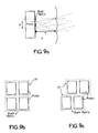
- the pixels can be arranged in rows and columns.
- Four pixels can be lit by a single ⁇ L lens, according to the lighting system in Figure 4, or each group of two pixels can be lit by one lens.
- the pixel lines are offset with respect to each other.
- Each group of two pixels is illuminated by a ⁇ L lens.
- FIGS. 11 and 12 it is also possible to design arrangements of lenses with respect to the pixels so that each lens illuminates several pixels.
- FIGS. 5a and 5b represent systems according to the invention in which the double DPC prism fulfills the functions of polarization separation, polarization rotation, and recombination of the beams in the direction of the liquid crystal screen.
- This system is based on the principle of total internal reflection with a view to combining the two beams.
- the non-polarized beam F is completely reflected by the first glass / air diopter D1.
- 50% of the beam intensity is transmitted for the right circular polarization (for example), and 50% is reflected by the cholesteric filter FC, then becomes incident to the right of the glass / air diopter D1, with an incident angle ⁇ 2 so that ⁇ 2 is less than this critical angle.
- the beam is then transmitted until it is reflected on the mirror M3 (metallized surface). Upon reflection, the direction of polarization reverses from right to left.
- this beam crosses the glass / air diopter D2 under the same conditions as those previously mentioned, as well as the cholesteric filter FC because the polarization is now suitably oriented.
- the resulting light beams F1 and F2 form an angle ⁇ suitable for lighting the liquid crystal screen.
- Figure 5c shows another polarization conversion system based on cholesteric filters. It is interesting to replace the mirror M3 with a retroreflector MR and a ⁇ / 4 plate to orient the plane of polarization of the incident light.
- the retroreflector (at 90 degrees) is practical because the incident light reflected on the retroreflector is parallel.
- Figure 5d shows another polarization conversion system based on the use of cholesteric filters.
- the non-polarized light is completely transmitted through two interfaces D1, D2 glass / air.
- the beam is then split into two parts: 50% of the circular polarized light is transmitted, the other part is reflected.
- the angle of incidence on the cholesteric filter FC is such that the reflected light is totally reflected internally, at the level of the glass / air interface.
- This beam is again reflected on the mirror M3 (at practically zero incidence) and sees its polarization reversed, then is reflected by the diopter D2 towards the filter FC.
- the DPC device thus provides two beams of the same polarization.
- the angle between the beams F1 and F2 is given by the fact that the filter FC is not perpendicular to the mirror M3.
- FIG. 5d provides for inclining the cholesteric filter FC relative to the optical axis of the system (relative to the beam F).
- the beam reflected by the filter FC is inclined relative to the beam F and therefore relative to F1.
- This inclination can be provided by providing an auxiliary prism P'1.
- FIG. 5e represents an alternative embodiment of the system of FIG. 5e in which the two prisms P1 and P2 are not isosceles at 45 °.
- the entry face A1 of the prism P2 makes with the hypotenuse of the prisms, an angle ⁇ less than 45 °.
- One of the polarizations is transmitted according to the beam F1 by the filter FC.
- the other polarization is reflected by the FC filter, the separation diopter of the two prisms and the mirror M3 to give the beam F2.
- the beam F2 then makes an angle with the beam F1.
- This system can be applied to the projection system via two "large" prisms.
- it is possible to design a fairly thin polarization converter by constituting a set of several small polarization conversion systems as shown in FIG. 6. In this way, we obtain the polarization converter having a thinner thickness.
- the operating principle is identical to that already mentioned above in particular in relation to FIG. 5d (in this case the FC filter is inclined at an angle a relative to the outlet faces of the prisms) or in relation to FIG. 5e .
- Circular polarized light (on the right for example) is reflected:
- Total internal reflection introduces a phase shift between the components s and p.
- the reflection on the mirror M3 introduces a phase shift ⁇ .
- the total internal reflection again introduces a phase shift - ⁇ between the components s & p.
- the total phase shift is ⁇ .
- the right polarized circular light becomes a left polarized circular light.
- each tooth has for example a first face perpendicular to the plane of the plates and a second face inclined substantially 45 °.
- the first face is metallized to form the M3 mirror.
- the P6 plate can have the FC cholesteric filter on its flat face.
- the prism system can be arranged along two possible directions: one along the long side of the LCD display, and the other along the short side.
- one along the long side of the LCD display and the other along the short side.
- FIG. 8a represents a variant according to which the cholesteric filter is placed between the two common faces of the two prisms.
- the cholesteric filter can be replaced by a variant using a HOE holographic element.
- the holographic optical element consisting of a phase volume diffracting element can provide an effective optical function when it is produced in a film thin (about 10 ⁇ m). These components are less expensive, light and can be combined with another optical function.
- the polarization separation function is obtained by recording the interference patterns of two coherent plane waves in a thin film photosensitive material.
- the variation of the induced index (dn) inside the material is important.
- the variations in the recording index make it possible to produce a mirror function for a polarization component (Brewster conditions at 45 degrees), the second polarization component being completely transmitted.
- Figure 8e shows an embodiment of the device of Figure 8a.
- the HOE holographic separator is produced on a glass plate and is glued to the hypotenuse face of the P1 prism using an index adapter product.
- the prisms P1 and P2 are each made in one piece with their metallized faces M7, M8.
- This type of component is commonly used for different colors (i.e. limited bandwidth).
- This conversion system of the invention of polarizations is therefore based on a very compact holographic optical polarizer.
- the latter can be used in a projection system for white light or for each color.
- Unpolarized light (white or monochrome) is incident on the HOE polarizer.
- Light polarized in an "S" direction is fully reflected.
- the "p" component is then transmitted twice on the HOE / air and air / glass limit. This component "p” is reflected by the inclined mirror, M8 and then by the phenomenon of total internal reflection (TIR).
- TIR total internal reflection
- the component "s” reflected by the HOE polarizer crosses twice a ⁇ / 4 plate and is reflected on the inclined mirror M7.
- the polarized beam of type "s" becomes a polarized beam of type "p".
- This beam again becomes incident on the HOE polarizer, then is transmitted completely: first by the HOE, then by the HOE / air and air / glass limits.
- the liquid crystal screen therefore receives two main beams F1, F2 polarized in the same way, each being focused by the microlenses on half of the pixels (on each line for example). Within each pixel, the focus depends solely on the lighting aperture of the lamp. It therefore does not present any difference if we disregard the polarization system.
- the focus is slightly offset from the axis.
- p is the horizontal step of the liquid crystal display (see figure 6a).
- f is the focal length of each microlens in the thickness of the glass or liquid crystal display.
- the recombiner may serve as an angular filter. Indeed, if the polarization converter is designed so as to obtain ⁇ ⁇ deg in air for example and the value of the extent of the lamp varies (during its lifetime or following its change), all the beams of angle greater than ⁇ , will be transmitted for one arm only (no internal total reflection), then reflected for the second arm and not transmitted in their entirety. In this way, the lighting box is an angle filter. This allows us to use a larger light source without affecting the contrast of the liquid crystal display.
- this beam can directly use this beam to illuminate the liquid crystal display of a monovalve or monochrome projector (see Figure 10) or for a three-valve system for three-color projection.
- this system there is an illumination unit which provides two beams as described above, the LCD screen and the microlens array ⁇ L.
Landscapes
- Physics & Mathematics (AREA)
- Nonlinear Science (AREA)
- Optics & Photonics (AREA)
- General Physics & Mathematics (AREA)
- Signal Processing (AREA)
- Mathematical Physics (AREA)
- Chemical & Material Sciences (AREA)
- Crystallography & Structural Chemistry (AREA)
- Multimedia (AREA)
- Engineering & Computer Science (AREA)
- Liquid Crystal (AREA)
- Projection Apparatus (AREA)
- Transforming Electric Information Into Light Information (AREA)
Applications Claiming Priority (2)
| Application Number | Priority Date | Filing Date | Title |
|---|---|---|---|
| FR9505113 | 1995-04-28 | ||
| FR9505113A FR2733619B1 (fr) | 1995-04-28 | 1995-04-28 | Systeme d'eclairement d'un ecran a cristal liquide |
Publications (2)
| Publication Number | Publication Date |
|---|---|
| EP0740476A1 true EP0740476A1 (de) | 1996-10-30 |
| EP0740476B1 EP0740476B1 (de) | 2000-10-25 |
Family
ID=9478535
Family Applications (1)
| Application Number | Title | Priority Date | Filing Date |
|---|---|---|---|
| EP96400876A Expired - Lifetime EP0740476B1 (de) | 1995-04-28 | 1996-04-24 | Vorrichtung zur Polarisationstrennung und Anwendung in einem Beleuchtungssystem einer Flüssigkristallanzeigevorrichtung |
Country Status (6)
| Country | Link |
|---|---|
| US (1) | US5877824A (de) |
| EP (1) | EP0740476B1 (de) |
| JP (1) | JP3657347B2 (de) |
| DE (1) | DE69610734T2 (de) |
| FR (1) | FR2733619B1 (de) |
| ZA (1) | ZA963007B (de) |
Families Citing this family (12)
| Publication number | Priority date | Publication date | Assignee | Title |
|---|---|---|---|---|
| JPH10293212A (ja) * | 1997-02-18 | 1998-11-04 | Dainippon Printing Co Ltd | バックライト及び液晶表示装置 |
| US6023370A (en) * | 1998-05-29 | 2000-02-08 | Primax Electronics Ltd. | Light polarizing device for generating a polarized light with different polarizations |
| TW460730B (en) * | 1998-11-13 | 2001-10-21 | Ind Tech Res Inst | Dual board Liquid crystal projection display |
| DE60144542D1 (de) * | 2000-01-28 | 2011-06-09 | Seiko Epson Corp | Lichtreflektierender Polarisator und Projektor damit |
| KR100370658B1 (ko) * | 2000-12-22 | 2003-02-05 | 삼성전기주식회사 | 색 분리 합성 장치 |
| US7196849B2 (en) * | 2003-05-22 | 2007-03-27 | Optical Research Associates | Apparatus and methods for illuminating optical systems |
| WO2004106983A2 (en) * | 2003-05-22 | 2004-12-09 | Optical Research Associates | Illumination in optical systems |
| WO2004106982A2 (en) * | 2003-05-22 | 2004-12-09 | Optical Research Associates | Optical combiner designs and head mounted displays |
| US7450310B2 (en) * | 2005-05-03 | 2008-11-11 | Optical Research Associates | Head mounted display devices |
| EP1792225A4 (de) | 2004-09-01 | 2010-07-28 | Optical Res Associates | Kompakte kopfmontierte anzeigevorrichtungen mit geneigtem/dezentriertem linsenelement |
| WO2007040725A1 (en) * | 2005-09-26 | 2007-04-12 | Avery Dennison Corporation | Retroreflective sheeting comprising a divergence enhancing layer |
| KR101403761B1 (ko) * | 2013-01-08 | 2014-06-03 | 김재희 | 스테레오스코픽 입체 영상 투영 장치 및 방법 |
Citations (4)
| Publication number | Priority date | Publication date | Assignee | Title |
|---|---|---|---|---|
| JPH05100331A (ja) * | 1991-10-11 | 1993-04-23 | Toshiba Corp | 液晶表示装置 |
| EP0552725A1 (de) * | 1992-01-21 | 1993-07-28 | Canon Kabushiki Kaisha | Vorrichtung zur Beleuchtung mit polarisiertem Licht und Projektor, der diese Vorrichtung verwendet |
| EP0609055A1 (de) * | 1993-01-25 | 1994-08-03 | Matsushita Electric Industrial Co., Ltd. | Lichtventilvorrichtung und Anzeigesystem die diese benutzt |
| EP0615148A2 (de) * | 1993-03-08 | 1994-09-14 | Ernst Prof. Dr.-Ing. habil. Lüder | Verfahren und Vorrichtung zur Polarisation von Licht |
Family Cites Families (8)
| Publication number | Priority date | Publication date | Assignee | Title |
|---|---|---|---|---|
| US4769750A (en) * | 1985-10-18 | 1988-09-06 | Nippon Kogaku K. K. | Illumination optical system |
| NL8901077A (nl) * | 1989-04-28 | 1990-11-16 | Koninkl Philips Electronics Nv | Optische belichtingsstelsel en projectie-apparaat voorzien van een dergelijk stelsel. |
| FR2676288B1 (fr) * | 1991-05-07 | 1994-06-17 | Thomson Csf | Collecteur d'eclairage pour projecteur. |
| JP2973750B2 (ja) * | 1992-03-31 | 1999-11-08 | 松下電器産業株式会社 | 照明光学装置とそれを用いた投写型表示装置 |
| US5506701A (en) * | 1993-01-28 | 1996-04-09 | Dai Nippon Printing Co., Ltd. | Hologram color filter, liquid crystal display device using the same, and fabrication process of hologram color filter |
| WO1995000865A1 (en) * | 1993-06-17 | 1995-01-05 | Xmr, Inc. | Improved optical beam integration system |
| JP3344635B2 (ja) * | 1993-12-27 | 2002-11-11 | シャープ株式会社 | カラー液晶表示装置 |
| US5737113A (en) * | 1995-08-04 | 1998-04-07 | Canon Kabushiki Kaisha | Optical modulators and color image display device employing the same |
-
1995
- 1995-04-28 FR FR9505113A patent/FR2733619B1/fr not_active Expired - Fee Related
-
1996
- 1996-04-16 US US08/633,242 patent/US5877824A/en not_active Expired - Fee Related
- 1996-04-16 ZA ZA963007A patent/ZA963007B/xx unknown
- 1996-04-24 DE DE69610734T patent/DE69610734T2/de not_active Expired - Fee Related
- 1996-04-24 EP EP96400876A patent/EP0740476B1/de not_active Expired - Lifetime
- 1996-04-30 JP JP10889296A patent/JP3657347B2/ja not_active Expired - Fee Related
Patent Citations (4)
| Publication number | Priority date | Publication date | Assignee | Title |
|---|---|---|---|---|
| JPH05100331A (ja) * | 1991-10-11 | 1993-04-23 | Toshiba Corp | 液晶表示装置 |
| EP0552725A1 (de) * | 1992-01-21 | 1993-07-28 | Canon Kabushiki Kaisha | Vorrichtung zur Beleuchtung mit polarisiertem Licht und Projektor, der diese Vorrichtung verwendet |
| EP0609055A1 (de) * | 1993-01-25 | 1994-08-03 | Matsushita Electric Industrial Co., Ltd. | Lichtventilvorrichtung und Anzeigesystem die diese benutzt |
| EP0615148A2 (de) * | 1993-03-08 | 1994-09-14 | Ernst Prof. Dr.-Ing. habil. Lüder | Verfahren und Vorrichtung zur Polarisation von Licht |
Non-Patent Citations (3)
| Title |
|---|
| "Improved Liquid Crystal Display panel illumination", IBM TECHNICAL DISCLOSURE BULLETIN, vol. 36, no. 09b, September 1993 (1993-09-01), pages 453 - 456, XP002009605 * |
| PATENT ABSTRACTS OF JAPAN vol. 16, no. 313 (P - 1383) 9 July 1992 (1992-07-09) * |
| PATENT ABSTRACTS OF JAPAN vol. 17, no. 448 (P - 1594) 17 August 1993 (1993-08-17) * |
Also Published As
| Publication number | Publication date |
|---|---|
| DE69610734T2 (de) | 2001-05-23 |
| DE69610734D1 (de) | 2000-11-30 |
| FR2733619A1 (fr) | 1996-10-31 |
| ZA963007B (en) | 1996-08-28 |
| US5877824A (en) | 1999-03-02 |
| JPH095699A (ja) | 1997-01-10 |
| EP0740476B1 (de) | 2000-10-25 |
| JP3657347B2 (ja) | 2005-06-08 |
| FR2733619B1 (fr) | 1997-06-27 |
Similar Documents
| Publication | Publication Date | Title |
|---|---|---|
| EP0740477B1 (de) | Vorrichtung zur Polarisationstrennung und Anwendung für ein Beleuchtungssystem eines Flüssigkristallschirms | |
| EP0633702B1 (de) | Farbanzeigegerät | |
| EP0475796B1 (de) | Bildprojektionssystem mit Verwendung von zwei orthogonalen Lichtpolarizationskomponenten | |
| EP0547949B1 (de) | Optischer Polarisationsstrahlenteiler und seine Verwendung in einem Abbildungssystem | |
| EP0512099B1 (de) | Bilddarstellungsgerät | |
| EP0451034B1 (de) | Vorrichtung für Bildprojektion | |
| EP0485268B1 (de) | Matrix-Bildprojektor mit zwei polarisierten Strahlen | |
| EP0778700B1 (de) | Verbesserung an Projektionssystemen | |
| FR2680882A1 (fr) | Projecteur d'images a efficacite lumineuse orptimisee. | |
| EP0880724A1 (de) | Anzeigevorrichtung und flacher fernsehbildschirm, der diese vorrichtung benutzt | |
| EP0740476B1 (de) | Vorrichtung zur Polarisationstrennung und Anwendung in einem Beleuchtungssystem einer Flüssigkristallanzeigevorrichtung | |
| EP0572292B1 (de) | Farbstrahlteiler und Abbildungsprojektor der diesen benutzt | |
| EP0549406B1 (de) | Polarisierender Strahlteiler und Anwendung in einem Anzeigegerät | |
| EP0757274B1 (de) | Optische Polarisationsvorrichtung und Flüssigkristall-Projektionssystem damit | |
| EP0762182A1 (de) | Hintergrundbeleuchtungssystem für elektrooptischen Modulator und Anzeigevorrichtung mit einem solchen Beleuchtungssystem | |
| FR2706666A1 (fr) | Panneau d'affichage à cristaux liquides et projecteur à cristaux liquides utilisant ce dernier. | |
| FR2762099A1 (fr) | Dispositif holographique de formation de faisceaux de lumiere colores, polarises et separes angulairement et projecteur d'images video en faisant application | |
| FR2707444A1 (fr) | Projecteur vidéo à cristaux liquides. | |
| FR2872588A1 (fr) | Systeme d'illumination pour imageur et projecteur correspondant | |
| WO1996019900A1 (fr) | Projecteur video a cristaux liquides | |
| FR2757669A1 (fr) | Systeme de visualisation et application a un systeme de traitement d'images |
Legal Events
| Date | Code | Title | Description |
|---|---|---|---|
| PUAI | Public reference made under article 153(3) epc to a published international application that has entered the european phase |
Free format text: ORIGINAL CODE: 0009012 |
|
| AK | Designated contracting states |
Kind code of ref document: A1 Designated state(s): DE FR GB |
|
| 17P | Request for examination filed |
Effective date: 19970219 |
|
| RAP1 | Party data changed (applicant data changed or rights of an application transferred) |
Owner name: THOMSON MULTIMEDIA |
|
| 17Q | First examination report despatched |
Effective date: 19981102 |
|
| GRAG | Despatch of communication of intention to grant |
Free format text: ORIGINAL CODE: EPIDOS AGRA |
|
| RTI1 | Title (correction) |
Free format text: POLARISATION SEPARATION DEVICE AND APPLICATION TO A LIQUID CRYSTAL DISPLAY ILLUMINATION SYSTEM |
|
| RTI1 | Title (correction) |
Free format text: POLARISATION SEPARATION DEVICE AND APPLICATION TO A LIQUID CRYSTAL DISPLAY ILLUMINATION SYSTEM |
|
| RTI1 | Title (correction) |
Free format text: POLARISATION SEPARATION DEVICE AND APPLICATION TO A LIQUID CRYSTAL DISPLAY ILLUMINATION SYSTEM |
|
| RTI1 | Title (correction) |
Free format text: POLARISATION SEPARATION DEVICE AND APPLICATION TO A LIQUID CRYSTAL DISPLAY ILLUMINATION SYSTEM |
|
| RTI1 | Title (correction) |
Free format text: POLARISATION SEPARATION DEVICE AND APPLICATION TO A LIQUID CRYSTAL DISPLAY ILLUMINATION SYSTEM |
|
| GRAG | Despatch of communication of intention to grant |
Free format text: ORIGINAL CODE: EPIDOS AGRA |
|
| GRAG | Despatch of communication of intention to grant |
Free format text: ORIGINAL CODE: EPIDOS AGRA |
|
| GRAH | Despatch of communication of intention to grant a patent |
Free format text: ORIGINAL CODE: EPIDOS IGRA |
|
| GRAH | Despatch of communication of intention to grant a patent |
Free format text: ORIGINAL CODE: EPIDOS IGRA |
|
| GRAA | (expected) grant |
Free format text: ORIGINAL CODE: 0009210 |
|
| AK | Designated contracting states |
Kind code of ref document: B1 Designated state(s): DE FR GB |
|
| PG25 | Lapsed in a contracting state [announced via postgrant information from national office to epo] |
Ref country code: FR Free format text: LAPSE BECAUSE OF FAILURE TO SUBMIT A TRANSLATION OF THE DESCRIPTION OR TO PAY THE FEE WITHIN THE PRESCRIBED TIME-LIMIT Effective date: 20001025 |
|
| RIN1 | Information on inventor provided before grant (corrected) |
Inventor name: SARAYEDDINE, KHALED |
|
| GBT | Gb: translation of ep patent filed (gb section 77(6)(a)/1977) |
Effective date: 20001025 |
|
| REF | Corresponds to: |
Ref document number: 69610734 Country of ref document: DE Date of ref document: 20001130 |
|
| EN | Fr: translation not filed | ||
| PLBE | No opposition filed within time limit |
Free format text: ORIGINAL CODE: 0009261 |
|
| STAA | Information on the status of an ep patent application or granted ep patent |
Free format text: STATUS: NO OPPOSITION FILED WITHIN TIME LIMIT |
|
| 26N | No opposition filed | ||
| REG | Reference to a national code |
Ref country code: GB Ref legal event code: 746 Effective date: 20011123 |
|
| REG | Reference to a national code |
Ref country code: GB Ref legal event code: IF02 |
|
| REG | Reference to a national code |
Ref country code: FR Ref legal event code: D6 |
|
| PGFP | Annual fee paid to national office [announced via postgrant information from national office to epo] |
Ref country code: DE Payment date: 20050418 Year of fee payment: 10 |
|
| PGFP | Annual fee paid to national office [announced via postgrant information from national office to epo] |
Ref country code: FR Payment date: 20050425 Year of fee payment: 10 |
|
| PGFP | Annual fee paid to national office [announced via postgrant information from national office to epo] |
Ref country code: GB Payment date: 20060310 Year of fee payment: 11 |
|
| PG25 | Lapsed in a contracting state [announced via postgrant information from national office to epo] |
Ref country code: DE Free format text: LAPSE BECAUSE OF NON-PAYMENT OF DUE FEES Effective date: 20061101 |
|
| GBPC | Gb: european patent ceased through non-payment of renewal fee |
Effective date: 20070424 |
|
| PG25 | Lapsed in a contracting state [announced via postgrant information from national office to epo] |
Ref country code: GB Free format text: LAPSE BECAUSE OF NON-PAYMENT OF DUE FEES Effective date: 20070424 |