EP1707361A2 - Rouleau applicateur pour un groupe d'impression offset - Google Patents
Rouleau applicateur pour un groupe d'impression offset Download PDFInfo
- Publication number
- EP1707361A2 EP1707361A2 EP06005821A EP06005821A EP1707361A2 EP 1707361 A2 EP1707361 A2 EP 1707361A2 EP 06005821 A EP06005821 A EP 06005821A EP 06005821 A EP06005821 A EP 06005821A EP 1707361 A2 EP1707361 A2 EP 1707361A2
- Authority
- EP
- European Patent Office
- Prior art keywords
- axis
- printing
- roll
- offset printing
- printing unit
- Prior art date
- Legal status (The legal status is an assumption and is not a legal conclusion. Google has not performed a legal analysis and makes no representation as to the accuracy of the status listed.)
- Granted
Links
Images


Classifications
-
- B—PERFORMING OPERATIONS; TRANSPORTING
- B41—PRINTING; LINING MACHINES; TYPEWRITERS; STAMPS
- B41F—PRINTING MACHINES OR PRESSES
- B41F31/00—Inking arrangements or devices
- B41F31/30—Arrangements for tripping, lifting, adjusting, or removing inking rollers; Supports, bearings, or forks therefor
- B41F31/301—Devices for tripping and adjusting form rollers
-
- B—PERFORMING OPERATIONS; TRANSPORTING
- B41—PRINTING; LINING MACHINES; TYPEWRITERS; STAMPS
- B41F—PRINTING MACHINES OR PRESSES
- B41F13/00—Common details of rotary presses or machines
- B41F13/08—Cylinders
- B41F13/20—Supports for bearings or supports for forme, offset, or impression cylinders
- B41F13/21—Bearer rings
-
- B—PERFORMING OPERATIONS; TRANSPORTING
- B41—PRINTING; LINING MACHINES; TYPEWRITERS; STAMPS
- B41F—PRINTING MACHINES OR PRESSES
- B41F31/00—Inking arrangements or devices
- B41F31/30—Arrangements for tripping, lifting, adjusting, or removing inking rollers; Supports, bearings, or forks therefor
- B41F31/304—Arrangements for inking roller bearings, forks or supports
- B41F31/305—Eccentric bearings
Definitions
- the invention relates to an applicator roll for an offset printing unit, having an axis and a roll shell rotatable about the axis, wherein the axis rotationally fixed in the offset printing unit can be fixed, in particular in a printing machine for the production of labels.
- Printing presses for the production of labels may have a number of interfaces or platforms for accommodating printing process-specific devices, so that a processing of a printing material, in particular a printing material web, can be carried out with different, depending on the order printing method.
- a processing of a printing material in particular a printing material web
- a recorded printing process-specific device in cooperation forms a printing unit of the corresponding printing process.
- Typical printing-specific devices often in the form of essays, trays, inserts or cassettes, include flexographic printing, screen printing, letterpress printing and offset printing.
- processing-process-specific devices which can also be accommodated on the platforms are made available, so that, for example, embossing of foil (hot and cold), gluing, punching or the like can take place on the printing substrate.
- the mentioned printing units can also be designed to be variable in format insofar as different cylinder diameters, in particular for the respective printing form cylinder, can be used.
- a format adaptation requires variable positioning of individual components or components in the printing process specific device.
- the positions of the applicator rollers In offset printing units, especially in variable format execution, the positions of the applicator rollers, those rollers which are in rolling contact with the printing form, must be set exactly. For various reasons, for example by roller wear, by temperature effects or by dimensional tolerances, a fine adjustment or readjustment during operation may be necessary.
- Typical application rollers are designed without drive and are caused by the frictional contact of the lateral surface with the lateral surface of a standing in WälzAuth other driven roller of the inking unit or ink fountain, in particular an iridescent Verreiberwalze, in rotational motion.
- the contact pressure consequently influences the force transmission and also the color transfer or color splitting in the nip of the contacting rollers.
- the axial force of an iridescent Verreiberwalze can be used to oscillate the applicator roll in the axial direction.
- a roller in a inking or dampening unit for a rotary printing machine which has a rotatably mounted in two bearing points pin rotatably mounted roll barrel.
- the axis of rotation of the roll bale with respect to the longitudinal axis of the pins is adjustable, in particular eccentrically pivotable. The adjustment can be made by means of a worm driven by a wheel or by a gear, which is in engagement with a rack.
- FR 2527988 discloses an applicator roll with a frame fixed recorded axis.
- the contact pressure of the roll mantle, which is received rotatably about the axis, against the mantle surface of an iridescent distributor roll can be adjusted by means of two eccentric pieces.
- the eccentric pieces are rotatable in the released state about the axis, so that the force effect can be changed with the adjustment of the angular position.
- screws which cause a clamping on the axis are provided.
- Object of the present invention is to provide an applicator roll, which allows a simple way positioning of the applicator roll in the printing unit.
- An applicator roll according to the invention for an offset printing unit has an axis, in particular a continuous shaft or two roll neck with common longitudinal axis, and a roll shell rotatable about the axis, wherein the axis rotatably or fixed to the frame fixed in offset printing, more precisely, the roll neck of the applicator roll can be fixed on ,
- the applicator roll comprises at least one bush, which carries a bearing for a rotatable about one of the two roll neck race and whose angular position on the axis is variable so that the race is adjusted eccentrically to the axis.
- the applicator roll comprises an eccentric to the axis adjustable socket, an eccentric bushing.
- the application roller according to the invention is particularly pronounced without drive.
- the roll neck can also be carried out separately.
- a race can also be referred to as a bearer ring.
- the sleeve of the applicator roll which is detached from the axis, in particular the roll neck, is axially adjustable and can be fixed on the axis, in particular the roll neck.
- the amplitude of the transverse stroke (the traversing movement) of the applicator roll can be adjusted by the distance of the sleeve is changed to a support disk on the axis.
- the transverse stroke of the applicator roll can be limited.
- the transverse stroke or the oscillation in the direction of the axis is induced by the action of an oscillating rolling contact roller.
- the adjustment functions of the eccentricity and the oscillation amplitude can be united in this embodiment of the applicator roll according to the invention.
- the eccentric to the axis position of the bushing of the applicator roll by means of a first and a second threaded pin which are niekbar in respective bores of the bush and both on each lying in the socket surface, in particular flat surface, the axis, in particular of the roll neck act, adjustable.
- the change in position of the tips of the setscrews causes relative tilting of the surface relative to a normal position of the surface (in which the sleeve is concentric with or without eccentricity with the axis), in other words causes rotation of the sleeve about a pivot axis relative to said axis such that the eccentricity is varied.
- the surfaces may also be part surfaces of a large area of the roll neck.
- the setscrews can also be screws.
- the adjustment is easily possible, since the bushings of the races in the installed state of the applicator roll, especially when it interacts with the printing form cylinder, conveniently, in particular from the outside, is accessible.
- the bushings of the races in the installed state of the applicator roll especially when it interacts with the printing form cylinder, conveniently, in particular from the outside, is accessible.
- offset printing units which are equipped with printing forme cylinder and blanket cylinder in inserts, cassettes or the like, they no longer need to be removed prior to adjustment. A possible loss of time due to possibly iterative optimization of the multiple setting is avoided. Good reproducibility of the settings is achieved.
- the bushing of the applicator roll according to the invention can have at least one first and one second bore for receiving a respective cylindrical pin, which serves as a stop for one of the threaded pins.
- an applicator roll according to the invention can also have on the other roll neck an eccentrically adjustable axis to the bush, which carries another bearing for a further race.
- the applicator roll can therefore be equipped with two eccentric bushes.
- Each of the two eccentric bushings can have the described inventive features.
- the bearing for a race of the applicator roll is a deep groove ball bearing.
- the roll shell of the applicator roll on at least one other bearing, in particular a needle roller bearing is rotatably received on the axis.
- an offset printing unit according to the invention with a printing form cylinder and a number of applicator rollers which can be set against the printing form cylinder has at least one application roller with features or combinations of features according to this illustration.
- at least one of the applicator rolls, preferably all but one or all of the applicator rolls, of the offset printing unit is an applicator roll having features or feature combinations as illustrated in this description.
- the applicator roll according to the invention can be used in an offset printing unit whose printing form cylinder and transfer cylinder are releasably connectable stored in the offset printing unit, so that cylinders with different diameters in the offset printing unit can be accommodated.
- the offset printing unit according to the invention with at least one application roller according to the invention can be a format-variable offset printing unit.
- An offset printing unit may preferably have three or four application rollers, of which two and in this case three application rollers have features according to the invention in that case.
- one of the applicator rollers can also be designed without eccentric adjustability.
- a printing machine in particular a label printing machine or a self-adhesive label printing machine.
- the printing machine may be a sheet-processing or web-processing printing press.
- the printing press is modular.
- the printing press may in particular be designed such that a variable arrangement of pressure-specific devices is possible, as has been outlined in the introduction to the description of this representation.
- Typical variable printing presses, in particular for label printing are known from the prior art: for example, embodiments of such printing presses are in the documents US 4,384,522 . WO87 / 04665 . EP 0 757 627 B1 and EP 0 687 559 A1 described.
- the use of the applicator roll according to the invention is to be seen in particular in connection with these machines or machine configurations.
- a printing press for processing printing substrate webs, in particular for producing labels or self-adhesive labels, comprises at least one platform for receiving printing process-specific devices and a counter-pressure cylinder assigned to the platform over which the printing material web runs, such that a recorded printing process-specific device cooperates with the impression cylinder Compressor forms the corresponding printing method, wherein one of the printing process-specific means comprises at least one applicator roll having features according to this representation, so that in the printing machine, an inventive offset printing unit is realized with the features described.
- FIG. 1 shows a view of an embodiment of an applicator roller 10 according to the invention with two eccentrically adjustable races 16, 18.
- the applicator roll 10 has a about its axis (see also Figure 3) rotatable roller shell 14, which consists of an elastic material and the fluid transfer (color Moisture transfer) on a rolling contact with the applicator roll 10 standing, not shown here printing plate in an offset printing unit is used.
- the exact amount of elasticity, d. H. the material with a certain modulus of elasticity to be used is known to the person skilled in the art.
- the materials used in the roll shells of several applicator rolls in an offset printing unit can have different elasticities.
- the race 16 and the further race 18 are each on a bushing 40, also referred to as an eccentric, added to the roll pin 20.
- the axis of the applicator roll 10 is fixed by means of a fastening screw 26, d. H. rotationally fixed in the construction of the offset printing unit, such as in the frame, on the frame or on the side wall, fixed.
- the applicator roll 10 is on both sides, d. H. Both shaft journals are recorded in the offset printing unit.
- the setscrews here in Figure 1 is to see the respective sleeve 40, the first set screw 22, and after rotation of the sleeve 40 with the associated race 16, 18 tightened again, so that the screws Socket 40 are fixed on the roll neck 20.
- FIG. 2 is a view along the axis of the embodiment of Figure 1.
- the roll neck 20 with the pivot axis 66 is spaced from the axis of symmetry 28 of the bearing supported by the sleeve 40, on the rotatable part of the race 16 is fixed to a maximum eccentricity 30 spaced.
- the axis of symmetry 28 coincides with the axis of the roll mantle 14.
- the axis of symmetry 28 is pivoted out of the plane III about the pivot axis 66, so that the length of the solder of the symmetry axis 28 (the intersection of the axis of symmetry 28th with the plane of the drawing) to the level III, in which the axis of the roll shell 14 is located, the set eccentricity of the eccentric represents.
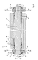
- FIG. 3 shows a section along the axis 12 of the embodiment from FIG. 1 (plane III in FIG. 2).
- the applicator roll 10 has a continuous eccentric shaft 32 with axis 12, which by means of a fastening screw 26, as already described with reference to the preceding Figures 1 and 2, rotatably received in not illustrated offset printing unit.
- the shaft journal 20 shown in the left part of Figure 3 carries a rotatable about the pivot axis 66 bushing 40, on which a bearing 34, here a deep groove ball bearing, is received, which is secured with a locking ring 38.
- the rotatable part of this bearing 38 carries the race 16, the tread 36 can cooperate with a tread of another roller.
- shaft journal carries another race 18 with the same structure just described.
- a sleeve 42 which is separated by a circular seal 44 of a support plate 46.
- the roll shell 14 is axially movable relative to the sleeves 42, the circular seals 44 and the support discs 46 and rotatably supported on the eccentric shaft by needle bearings 48 which are separated by a space with grease 50. While in the left part of Figure 3, the needle bearing 48 is shown at the stop of the support disk 46, in the right part of Figure 3, a space between the needle bearing and support disk can be seen.
- the applicator roller If, as already mentioned, the applicator roller is in rolling contact with an iridescent distributor roller of the fluid movement of the offset printing unit, it is transmitted to the applicator roller 10 not only a rotational action but also an oscillation effect in the direction of the axis 12.
- the amplitude of the oscillating movement of the applicator roll is limited by the spacing of the support disks 46.
- the possible transverse stroke 52 is determined by the adjustable axial position of the support disks 46. In FIG. 3, the distance of the needle ball bearing shown in the right-hand part from the support disk is the maximum transverse stroke 52 of the oscillating movement.
- the bushes 40 are detachably connected to the eccentric shaft 32 and its axial position can be adjusted, ie the axial Position of the support disk 46 can be changed with the sleeve 40, so that the possible transverse stroke 52 is adjustable.
- FIG 4 is a schematic representation of the basic position of the eccentric in section of the plane IV of Figure 3 shown when the end faces of the threaded pins 22, 24 (locking screws) flush with are the holes in the socket.
- the bush 40 has a first cylindrical pin 54 in a first bore 56 and a second cylindrical pin 60 in a second bore 62, wherein the holes 56, 60 extend into the holes of the threaded pins 22,24.
- the end faces of the set screws 22, 24 are in contact with the roll neck 20, more specifically the end face of the first set screw 22 contacts a first face 62 and the end face of the second set screw 24 contacts a second face 64 of the roll neck.
- a clamping and associated fixation of the beech 40 on the shaft journal is effected.
- the end surfaces of the threaded pins 22, 24 act on these surfaces 62, 64 such that the position of the threaded pins 22,24 in the holes determines the angular position of the sleeve 40 relative to the roll neck 20.
- the grub screws can be loosened so that the beech 40 can be rotated about the pivot axis 66 of the shaft journal 20 from a first angular position and brought into a second angular position and can be fixed therein again.
- the roll neck 20 is designed such that in the gap formed with the sleeve 40 there is sufficient play for a rotation in both directions of rotation.
- 20 material is removed from the generally cylindrical body of the roll neck, so that it has a prismatic shape in the vicinity of the threaded pins 22, 24.
- the surfaces 62, 64 do not intersect the circular arc of the cylindrical body at right angles, but are slightly inclined to the end face of the threaded pins 22, 24 executed in the basic position.
- the surfaces of the prismatic shape and the surfaces 62, 64 each include a right angle.
- FIG. 5 relates schematically to an angular position of the eccentric in the section of the plane V 3, in which an eccentricity of the other race 18 is set differently from zero.
- the bushing 40 has been rotated by 10 degrees from the basic position shown in Figure 4 clockwise about the pivot axis 66, while the first set screw 22 is sunk below the surface of the beech 40 and the second set screw 24 protrudes beyond the surface of the sleeve 40 out , In this situation shown, the operation of the first cylindrical pin 54 in the first bore 56 as a movable stop for the first set screw 22, the end face is now applied to the first cylindrical pin 54, can be seen.
- the mobility of the stopper is required due to the relative rotation to the roll neck 20. It is immediately clear to the person skilled in the art that after a rotation of about 10 degrees from the basic position shown in FIG. 4 in the other direction of rotation (counterclockwise) in an analogous situation for the second cylinder pin 58 in the second bore 60 results. A clamping of the sleeve 40 in the rotated angular position is further achieved by the action of the end faces of the set screws 22, 24 on the surfaces 62, 64 of the roll neck 20.
Landscapes
- Engineering & Computer Science (AREA)
- Mechanical Engineering (AREA)
- Coating Apparatus (AREA)
- Labeling Devices (AREA)
Applications Claiming Priority (1)
| Application Number | Priority Date | Filing Date | Title |
|---|---|---|---|
| DE200510015046 DE102005015046A1 (de) | 2005-03-31 | 2005-03-31 | Farbauftragswalze für ein Offsetdruckwerk |
Publications (3)
| Publication Number | Publication Date |
|---|---|
| EP1707361A2 true EP1707361A2 (fr) | 2006-10-04 |
| EP1707361A3 EP1707361A3 (fr) | 2008-07-02 |
| EP1707361B1 EP1707361B1 (fr) | 2013-05-15 |
Family
ID=36658575
Family Applications (1)
| Application Number | Title | Priority Date | Filing Date |
|---|---|---|---|
| EP20060005821 Expired - Lifetime EP1707361B1 (fr) | 2005-03-31 | 2006-03-22 | Rouleau applicateur pour un groupe d'impression offset |
Country Status (3)
| Country | Link |
|---|---|
| EP (1) | EP1707361B1 (fr) |
| DE (1) | DE102005015046A1 (fr) |
| DK (1) | DK1707361T3 (fr) |
Families Citing this family (3)
| Publication number | Priority date | Publication date | Assignee | Title |
|---|---|---|---|---|
| DE102015212572A1 (de) | 2015-07-06 | 2017-01-12 | Gallus Druckmaschinen Gmbh | Bearbeitungswerk zur rotativen Bearbeitung |
| DE102016215986A1 (de) | 2016-08-25 | 2018-03-01 | Gallus Druckmaschinen Gmbh | Bearbeitungswerk und Etikettendruckmaschine mit einem solchen Bearbeitungswerk |
| DE102016215988A1 (de) | 2016-08-25 | 2018-03-01 | Gallus Druckmaschinen Gmbh | Bearbeitungswerk und Etikettendruckmaschine mit einem solchen Bearbeitungswerk |
Citations (4)
| Publication number | Priority date | Publication date | Assignee | Title |
|---|---|---|---|---|
| US3732814A (en) | 1971-12-15 | 1973-05-15 | Rockwell International Corp | Bearer arrangement for offset printing press |
| FR2527988A1 (fr) | 1982-06-04 | 1983-12-09 | Creusot Loire | Dispositif d'encrage pour machine d'impression |
| DE19631176C1 (de) | 1996-08-02 | 1998-01-02 | Koenig & Bauer Albert Ag | Walze |
| DE19961190A1 (de) | 1999-12-18 | 2001-06-21 | Roland Man Druckmasch | Selbst ein- und nachstellende Lagerung für Walzen eines Farb- oder Feuchtwerkes einer Druckmaschine |
Family Cites Families (10)
| Publication number | Priority date | Publication date | Assignee | Title |
|---|---|---|---|---|
| DE1003760B (de) * | 1952-10-14 | 1957-03-07 | Winkler Maschf | Walzensupport fuer das Lagern von Farbwerkwalzen an Buchdruck-, Offsetdruck- u. dgl.Maschinen |
| DE1145640B (de) * | 1959-03-14 | 1963-03-21 | Planeta Veb Druckmasch Werke | Abschwenkbarer Reibzylinder in Farb- und Feuchtwerken von Druckmaschinen |
| US4384522A (en) * | 1977-12-07 | 1983-05-24 | Paper Converting Machine Company | Apparatus for producing business forms |
| GB8602561D0 (en) * | 1986-02-03 | 1986-03-12 | Morgan J H | Printing apparatus |
| DE3811337A1 (de) * | 1988-04-02 | 1989-10-19 | Kotterer Grafotec | Dosierwalze |
| EP0757627B1 (fr) * | 1994-04-28 | 1998-07-08 | Nilpeter A/S | Appareil d'impression comportant au moins un module d'impression |
| EP0687559A1 (fr) * | 1994-06-15 | 1995-12-20 | Ferd. Rüesch AG. | Installation avec des unités d'impression en série |
| DE19947224A1 (de) * | 1999-10-01 | 2001-04-05 | Koenig & Bauer Ag | Kurzfarbwerk |
| DE10006124A1 (de) * | 2000-02-11 | 2001-08-16 | Hauni Maschinenbau Ag | Druckwerk zum Bedrucken eines Hüllstreifens für Rauchartikel |
| DE10137980B4 (de) * | 2001-08-02 | 2004-09-30 | Koenig & Bauer Ag | Vorrichtung zur Betätigung einer verstellbar in einer Exzenterbuchse gelagerten Walze |
-
2005
- 2005-03-31 DE DE200510015046 patent/DE102005015046A1/de not_active Ceased
-
2006
- 2006-03-22 EP EP20060005821 patent/EP1707361B1/fr not_active Expired - Lifetime
- 2006-03-22 DK DK06005821T patent/DK1707361T3/da active
Patent Citations (4)
| Publication number | Priority date | Publication date | Assignee | Title |
|---|---|---|---|---|
| US3732814A (en) | 1971-12-15 | 1973-05-15 | Rockwell International Corp | Bearer arrangement for offset printing press |
| FR2527988A1 (fr) | 1982-06-04 | 1983-12-09 | Creusot Loire | Dispositif d'encrage pour machine d'impression |
| DE19631176C1 (de) | 1996-08-02 | 1998-01-02 | Koenig & Bauer Albert Ag | Walze |
| DE19961190A1 (de) | 1999-12-18 | 2001-06-21 | Roland Man Druckmasch | Selbst ein- und nachstellende Lagerung für Walzen eines Farb- oder Feuchtwerkes einer Druckmaschine |
Also Published As
| Publication number | Publication date |
|---|---|
| DK1707361T3 (da) | 2013-06-17 |
| EP1707361B1 (fr) | 2013-05-15 |
| DE102005015046A1 (de) | 2006-10-05 |
| EP1707361A3 (fr) | 2008-07-02 |
Similar Documents
| Publication | Publication Date | Title |
|---|---|---|
| EP0813959B1 (fr) | Cylindre entraíné | |
| EP0894623B1 (fr) | Groupe imprimant pour une machine rotative | |
| EP0328879B1 (fr) | Fourchette de rouleau pour presses rotatives | |
| DE1486854A1 (de) | Rotationsdruckmaschinen zum Bedrucken von Papierrollen | |
| EP0087625B1 (fr) | Dispositif pour l'application des rouleaux toucheurs sur le cylindre porte-plaque des machines d'impression et pour l'enlèvement et le réglage de ces rouleaux | |
| DE2130278C3 (de) | Druckeinheit einer Rollenrotationsdruckmaschine zum wahlweisen Hoch- oder Flachdruck | |
| EP0523367B1 (fr) | Cylindre de guidage du papier dans des machines rotatives à imprimer des feuilles | |
| EP0509414A1 (fr) | Unité d'impression pour une presse rotative | |
| EP1568494A1 (fr) | Dispositif pour réaliser des impression à format variable dans des machines à imprimer offset | |
| EP1707361B1 (fr) | Rouleau applicateur pour un groupe d'impression offset | |
| DE4400563C2 (de) | Walze in einem Farbwerk oder Feuchtwerk einer Rotationsdruckmaschine | |
| DE10111068A1 (de) | Walzenschloss zum lösbaren Befestigen einer Walze in einer Druckmaschine | |
| EP0267504B1 (fr) | Palier pour rouleaux applicateurs à mouvement de va-et-vient dans les machines d'impression | |
| DE4344365C2 (de) | Druckwerk für eine Rotationsdruckmaschine | |
| DE4013416C1 (fr) | ||
| EP2057017B1 (fr) | Élément d'impression d'une machine d'héliogravure | |
| DE2940879A1 (de) | Vorrichtung zum biegen einer druckwalze in einer rotationsdruckmaschine | |
| EP0606584A1 (fr) | Palier pour un cylindre de clichés équipé d'un tube enfilable | |
| DE10304285A1 (de) | Farbkasten | |
| EP1042123B1 (fr) | Rouleau | |
| EP1466733B1 (fr) | Support pour une chambre de racle dans une rotatif à imprimer | |
| EP0021006A1 (fr) | Dispositif pour limiter les oscillations de flexion dans les machines d'impression rotatives en offset | |
| DE102004022007B4 (de) | Lagerung für eine Walze einer Rotationsdruckmaschine, insbesondere für eine Auftragwalze eines Lackwerks | |
| CH687603A5 (de) | Anordnung zum Einstellen des Lagerspiels bei Zylindern von Druckmaschinen. | |
| DD149187A5 (de) | Vorrichtung zum dosieren einer fluessigkeit an einem von zwei walzen gebildeten spalt |
Legal Events
| Date | Code | Title | Description |
|---|---|---|---|
| PUAI | Public reference made under article 153(3) epc to a published international application that has entered the european phase |
Free format text: ORIGINAL CODE: 0009012 |
|
| AK | Designated contracting states |
Kind code of ref document: A2 Designated state(s): AT BE BG CH CY CZ DE DK EE ES FI FR GB GR HU IE IS IT LI LT LU LV MC NL PL PT RO SE SI SK TR |
|
| AX | Request for extension of the european patent |
Extension state: AL BA HR MK YU |
|
| PUAL | Search report despatched |
Free format text: ORIGINAL CODE: 0009013 |
|
| AK | Designated contracting states |
Kind code of ref document: A3 Designated state(s): AT BE BG CH CY CZ DE DK EE ES FI FR GB GR HU IE IS IT LI LT LU LV MC NL PL PT RO SE SI SK TR |
|
| AX | Request for extension of the european patent |
Extension state: AL BA HR MK YU |
|
| 17P | Request for examination filed |
Effective date: 20090105 |
|
| AKX | Designation fees paid |
Designated state(s): AT BE BG CH CY CZ DE DK EE ES FI FR GB GR HU IE IS IT LI LT LU LV MC NL PL PT RO SE SI SK TR |
|
| 17Q | First examination report despatched |
Effective date: 20090226 |
|
| GRAP | Despatch of communication of intention to grant a patent |
Free format text: ORIGINAL CODE: EPIDOSNIGR1 |
|
| GRAS | Grant fee paid |
Free format text: ORIGINAL CODE: EPIDOSNIGR3 |
|
| GRAA | (expected) grant |
Free format text: ORIGINAL CODE: 0009210 |
|
| AK | Designated contracting states |
Kind code of ref document: B1 Designated state(s): AT BE BG CH CY CZ DE DK EE ES FI FR GB GR HU IE IS IT LI LT LU LV MC NL PL PT RO SE SI SK TR |
|
| REG | Reference to a national code |
Ref country code: GB Ref legal event code: FG4D Free format text: NOT ENGLISH Ref country code: CH Ref legal event code: EP |
|
| REG | Reference to a national code |
Ref country code: AT Ref legal event code: REF Ref document number: 611916 Country of ref document: AT Kind code of ref document: T Effective date: 20130615 |
|
| REG | Reference to a national code |
Ref country code: DK Ref legal event code: T3 |
|
| REG | Reference to a national code |
Ref country code: IE Ref legal event code: FG4D Free format text: LANGUAGE OF EP DOCUMENT: GERMAN |
|
| REG | Reference to a national code |
Ref country code: DE Ref legal event code: R096 Ref document number: 502006012829 Country of ref document: DE Effective date: 20130711 |
|
| REG | Reference to a national code |
Ref country code: NL Ref legal event code: T3 |
|
| REG | Reference to a national code |
Ref country code: LT Ref legal event code: MG4D |
|
| PG25 | Lapsed in a contracting state [announced via postgrant information from national office to epo] |
Ref country code: PT Free format text: LAPSE BECAUSE OF FAILURE TO SUBMIT A TRANSLATION OF THE DESCRIPTION OR TO PAY THE FEE WITHIN THE PRESCRIBED TIME-LIMIT Effective date: 20130916 Ref country code: SI Free format text: LAPSE BECAUSE OF FAILURE TO SUBMIT A TRANSLATION OF THE DESCRIPTION OR TO PAY THE FEE WITHIN THE PRESCRIBED TIME-LIMIT Effective date: 20130515 Ref country code: SE Free format text: LAPSE BECAUSE OF FAILURE TO SUBMIT A TRANSLATION OF THE DESCRIPTION OR TO PAY THE FEE WITHIN THE PRESCRIBED TIME-LIMIT Effective date: 20130515 Ref country code: FI Free format text: LAPSE BECAUSE OF FAILURE TO SUBMIT A TRANSLATION OF THE DESCRIPTION OR TO PAY THE FEE WITHIN THE PRESCRIBED TIME-LIMIT Effective date: 20130515 Ref country code: IS Free format text: LAPSE BECAUSE OF FAILURE TO SUBMIT A TRANSLATION OF THE DESCRIPTION OR TO PAY THE FEE WITHIN THE PRESCRIBED TIME-LIMIT Effective date: 20130915 Ref country code: GR Free format text: LAPSE BECAUSE OF FAILURE TO SUBMIT A TRANSLATION OF THE DESCRIPTION OR TO PAY THE FEE WITHIN THE PRESCRIBED TIME-LIMIT Effective date: 20130816 Ref country code: LT Free format text: LAPSE BECAUSE OF FAILURE TO SUBMIT A TRANSLATION OF THE DESCRIPTION OR TO PAY THE FEE WITHIN THE PRESCRIBED TIME-LIMIT Effective date: 20130515 Ref country code: ES Free format text: LAPSE BECAUSE OF FAILURE TO SUBMIT A TRANSLATION OF THE DESCRIPTION OR TO PAY THE FEE WITHIN THE PRESCRIBED TIME-LIMIT Effective date: 20130826 |
|
| PG25 | Lapsed in a contracting state [announced via postgrant information from national office to epo] |
Ref country code: PL Free format text: LAPSE BECAUSE OF FAILURE TO SUBMIT A TRANSLATION OF THE DESCRIPTION OR TO PAY THE FEE WITHIN THE PRESCRIBED TIME-LIMIT Effective date: 20130515 Ref country code: BG Free format text: LAPSE BECAUSE OF FAILURE TO SUBMIT A TRANSLATION OF THE DESCRIPTION OR TO PAY THE FEE WITHIN THE PRESCRIBED TIME-LIMIT Effective date: 20130815 |
|
| PG25 | Lapsed in a contracting state [announced via postgrant information from national office to epo] |
Ref country code: LV Free format text: LAPSE BECAUSE OF FAILURE TO SUBMIT A TRANSLATION OF THE DESCRIPTION OR TO PAY THE FEE WITHIN THE PRESCRIBED TIME-LIMIT Effective date: 20130515 |
|
| PG25 | Lapsed in a contracting state [announced via postgrant information from national office to epo] |
Ref country code: EE Free format text: LAPSE BECAUSE OF FAILURE TO SUBMIT A TRANSLATION OF THE DESCRIPTION OR TO PAY THE FEE WITHIN THE PRESCRIBED TIME-LIMIT Effective date: 20130515 Ref country code: SK Free format text: LAPSE BECAUSE OF FAILURE TO SUBMIT A TRANSLATION OF THE DESCRIPTION OR TO PAY THE FEE WITHIN THE PRESCRIBED TIME-LIMIT Effective date: 20130515 Ref country code: CZ Free format text: LAPSE BECAUSE OF FAILURE TO SUBMIT A TRANSLATION OF THE DESCRIPTION OR TO PAY THE FEE WITHIN THE PRESCRIBED TIME-LIMIT Effective date: 20130515 |
|
| PG25 | Lapsed in a contracting state [announced via postgrant information from national office to epo] |
Ref country code: RO Free format text: LAPSE BECAUSE OF FAILURE TO SUBMIT A TRANSLATION OF THE DESCRIPTION OR TO PAY THE FEE WITHIN THE PRESCRIBED TIME-LIMIT Effective date: 20130515 |
|
| PLBE | No opposition filed within time limit |
Free format text: ORIGINAL CODE: 0009261 |
|
| STAA | Information on the status of an ep patent application or granted ep patent |
Free format text: STATUS: NO OPPOSITION FILED WITHIN TIME LIMIT |
|
| 26N | No opposition filed |
Effective date: 20140218 |
|
| REG | Reference to a national code |
Ref country code: DE Ref legal event code: R097 Ref document number: 502006012829 Country of ref document: DE Effective date: 20140218 |
|
| PG25 | Lapsed in a contracting state [announced via postgrant information from national office to epo] |
Ref country code: LU Free format text: LAPSE BECAUSE OF FAILURE TO SUBMIT A TRANSLATION OF THE DESCRIPTION OR TO PAY THE FEE WITHIN THE PRESCRIBED TIME-LIMIT Effective date: 20140322 |
|
| GBPC | Gb: european patent ceased through non-payment of renewal fee |
Effective date: 20140322 |
|
| REG | Reference to a national code |
Ref country code: FR Ref legal event code: ST Effective date: 20141128 |
|
| REG | Reference to a national code |
Ref country code: IE Ref legal event code: MM4A |
|
| PG25 | Lapsed in a contracting state [announced via postgrant information from national office to epo] |
Ref country code: IE Free format text: LAPSE BECAUSE OF NON-PAYMENT OF DUE FEES Effective date: 20140322 Ref country code: FR Free format text: LAPSE BECAUSE OF NON-PAYMENT OF DUE FEES Effective date: 20140331 Ref country code: GB Free format text: LAPSE BECAUSE OF NON-PAYMENT OF DUE FEES Effective date: 20140322 |
|
| PGFP | Annual fee paid to national office [announced via postgrant information from national office to epo] |
Ref country code: DK Payment date: 20150319 Year of fee payment: 10 Ref country code: NL Payment date: 20150319 Year of fee payment: 10 Ref country code: IT Payment date: 20150227 Year of fee payment: 10 Ref country code: CH Payment date: 20150319 Year of fee payment: 10 |
|
| REG | Reference to a national code |
Ref country code: AT Ref legal event code: MM01 Ref document number: 611916 Country of ref document: AT Kind code of ref document: T Effective date: 20140322 |
|
| PGFP | Annual fee paid to national office [announced via postgrant information from national office to epo] |
Ref country code: DE Payment date: 20150331 Year of fee payment: 10 |
|
| PG25 | Lapsed in a contracting state [announced via postgrant information from national office to epo] |
Ref country code: AT Free format text: LAPSE BECAUSE OF NON-PAYMENT OF DUE FEES Effective date: 20140322 |
|
| PG25 | Lapsed in a contracting state [announced via postgrant information from national office to epo] |
Ref country code: MC Free format text: LAPSE BECAUSE OF FAILURE TO SUBMIT A TRANSLATION OF THE DESCRIPTION OR TO PAY THE FEE WITHIN THE PRESCRIBED TIME-LIMIT Effective date: 20130515 |
|
| PG25 | Lapsed in a contracting state [announced via postgrant information from national office to epo] |
Ref country code: CY Free format text: LAPSE BECAUSE OF FAILURE TO SUBMIT A TRANSLATION OF THE DESCRIPTION OR TO PAY THE FEE WITHIN THE PRESCRIBED TIME-LIMIT Effective date: 20130515 |
|
| PG25 | Lapsed in a contracting state [announced via postgrant information from national office to epo] |
Ref country code: HU Free format text: LAPSE BECAUSE OF FAILURE TO SUBMIT A TRANSLATION OF THE DESCRIPTION OR TO PAY THE FEE WITHIN THE PRESCRIBED TIME-LIMIT; INVALID AB INITIO Effective date: 20060322 Ref country code: TR Free format text: LAPSE BECAUSE OF FAILURE TO SUBMIT A TRANSLATION OF THE DESCRIPTION OR TO PAY THE FEE WITHIN THE PRESCRIBED TIME-LIMIT Effective date: 20130515 |
|
| REG | Reference to a national code |
Ref country code: DE Ref legal event code: R119 Ref document number: 502006012829 Country of ref document: DE |
|
| REG | Reference to a national code |
Ref country code: DK Ref legal event code: EBP Effective date: 20160331 |
|
| REG | Reference to a national code |
Ref country code: CH Ref legal event code: PL |
|
| REG | Reference to a national code |
Ref country code: NL Ref legal event code: MM Effective date: 20160401 |
|
| PG25 | Lapsed in a contracting state [announced via postgrant information from national office to epo] |
Ref country code: LI Free format text: LAPSE BECAUSE OF NON-PAYMENT OF DUE FEES Effective date: 20160331 Ref country code: DE Free format text: LAPSE BECAUSE OF NON-PAYMENT OF DUE FEES Effective date: 20161001 Ref country code: NL Free format text: LAPSE BECAUSE OF NON-PAYMENT OF DUE FEES Effective date: 20160401 Ref country code: CH Free format text: LAPSE BECAUSE OF NON-PAYMENT OF DUE FEES Effective date: 20160331 |
|
| PG25 | Lapsed in a contracting state [announced via postgrant information from national office to epo] |
Ref country code: IT Free format text: LAPSE BECAUSE OF NON-PAYMENT OF DUE FEES Effective date: 20160322 |
|
| PG25 | Lapsed in a contracting state [announced via postgrant information from national office to epo] |
Ref country code: DK Free format text: LAPSE BECAUSE OF NON-PAYMENT OF DUE FEES Effective date: 20160331 |
|
| PG25 | Lapsed in a contracting state [announced via postgrant information from national office to epo] |
Ref country code: BE Free format text: LAPSE BECAUSE OF NON-PAYMENT OF DUE FEES Effective date: 20140331 |