EP0741347B1 - Méthode et appareil pour produire des signes avec des lettres prismatiques et des images graphiques - Google Patents
Méthode et appareil pour produire des signes avec des lettres prismatiques et des images graphiques Download PDFInfo
- Publication number
- EP0741347B1 EP0741347B1 EP96106365A EP96106365A EP0741347B1 EP 0741347 B1 EP0741347 B1 EP 0741347B1 EP 96106365 A EP96106365 A EP 96106365A EP 96106365 A EP96106365 A EP 96106365A EP 0741347 B1 EP0741347 B1 EP 0741347B1
- Authority
- EP
- European Patent Office
- Prior art keywords
- tool
- cutting
- sheet material
- offset
- graphic image
- Prior art date
- Legal status (The legal status is an assumption and is not a legal conclusion. Google has not performed a legal analysis and makes no representation as to the accuracy of the status listed.)
- Expired - Lifetime
Links
Images



Classifications
-
- B—PERFORMING OPERATIONS; TRANSPORTING
- B23—MACHINE TOOLS; METAL-WORKING NOT OTHERWISE PROVIDED FOR
- B23Q—DETAILS, COMPONENTS, OR ACCESSORIES FOR MACHINE TOOLS, e.g. ARRANGEMENTS FOR COPYING OR CONTROLLING; MACHINE TOOLS IN GENERAL CHARACTERISED BY THE CONSTRUCTION OF PARTICULAR DETAILS OR COMPONENTS; COMBINATIONS OR ASSOCIATIONS OF METAL-WORKING MACHINES, NOT DIRECTED TO A PARTICULAR RESULT
- B23Q15/00—Automatic control or regulation of feed movement, cutting velocity or position of tool or work
-
- G—PHYSICS
- G05—CONTROLLING; REGULATING
- G05B—CONTROL OR REGULATING SYSTEMS IN GENERAL; FUNCTIONAL ELEMENTS OF SUCH SYSTEMS; MONITORING OR TESTING ARRANGEMENTS FOR SUCH SYSTEMS OR ELEMENTS
- G05B19/00—Program-control systems
- G05B19/02—Program-control systems electric
- G05B19/18—Numerical control [NC], i.e. automatically operating machines, in particular machine tools, e.g. in a manufacturing environment, so as to execute positioning, movement or co-ordinated operations by means of program data in numerical form
- G05B19/4097—Numerical control [NC], i.e. automatically operating machines, in particular machine tools, e.g. in a manufacturing environment, so as to execute positioning, movement or co-ordinated operations by means of program data in numerical form characterised by using design data to control NC machines, e.g. CAD/CAM
-
- G—PHYSICS
- G05—CONTROLLING; REGULATING
- G05B—CONTROL OR REGULATING SYSTEMS IN GENERAL; FUNCTIONAL ELEMENTS OF SUCH SYSTEMS; MONITORING OR TESTING ARRANGEMENTS FOR SUCH SYSTEMS OR ELEMENTS
- G05B2219/00—Program-control systems
- G05B2219/30—Nc systems
- G05B2219/35—Nc in input of data, input till input file format
- G05B2219/35533—Use, input 2-D data, sectional profile to machine 3-D surface
-
- G—PHYSICS
- G05—CONTROLLING; REGULATING
- G05B—CONTROL OR REGULATING SYSTEMS IN GENERAL; FUNCTIONAL ELEMENTS OF SUCH SYSTEMS; MONITORING OR TESTING ARRANGEMENTS FOR SUCH SYSTEMS OR ELEMENTS
- G05B2219/00—Program-control systems
- G05B2219/30—Nc systems
- G05B2219/36—Nc in input of data, input key till input tape
- G05B2219/36266—Tool path editor, for offset, multi-passes
-
- G—PHYSICS
- G05—CONTROLLING; REGULATING
- G05B—CONTROL OR REGULATING SYSTEMS IN GENERAL; FUNCTIONAL ELEMENTS OF SUCH SYSTEMS; MONITORING OR TESTING ARRANGEMENTS FOR SUCH SYSTEMS OR ELEMENTS
- G05B2219/00—Program-control systems
- G05B2219/30—Nc systems
- G05B2219/45—Nc applications
- G05B2219/45212—Etching, engraving, sculpturing, carving
-
- G—PHYSICS
- G05—CONTROLLING; REGULATING
- G05B—CONTROL OR REGULATING SYSTEMS IN GENERAL; FUNCTIONAL ELEMENTS OF SUCH SYSTEMS; MONITORING OR TESTING ARRANGEMENTS FOR SUCH SYSTEMS OR ELEMENTS
- G05B2219/00—Program-control systems
- G05B2219/30—Nc systems
- G05B2219/49—Nc machine tool, till multiple
- G05B2219/49241—2-5-D lace cutting, work in xy and increment in z, repeat
-
- G—PHYSICS
- G05—CONTROLLING; REGULATING
- G05B—CONTROL OR REGULATING SYSTEMS IN GENERAL; FUNCTIONAL ELEMENTS OF SUCH SYSTEMS; MONITORING OR TESTING ARRANGEMENTS FOR SUCH SYSTEMS OR ELEMENTS
- G05B2219/00—Program-control systems
- G05B2219/30—Nc systems
- G05B2219/49—Nc machine tool, till multiple
- G05B2219/49392—Multipasses, segmentation of cut, paraxial cutting
-
- Y—GENERAL TAGGING OF NEW TECHNOLOGICAL DEVELOPMENTS; GENERAL TAGGING OF CROSS-SECTIONAL TECHNOLOGIES SPANNING OVER SEVERAL SECTIONS OF THE IPC; TECHNICAL SUBJECTS COVERED BY FORMER USPC CROSS-REFERENCE ART COLLECTIONS [XRACs] AND DIGESTS
- Y10—TECHNICAL SUBJECTS COVERED BY FORMER USPC
- Y10T—TECHNICAL SUBJECTS COVERED BY FORMER US CLASSIFICATION
- Y10T409/00—Gear cutting, milling, or planing
- Y10T409/30—Milling
- Y10T409/30084—Milling with regulation of operation by templet, card, or other replaceable information supply
-
- Y—GENERAL TAGGING OF NEW TECHNOLOGICAL DEVELOPMENTS; GENERAL TAGGING OF CROSS-SECTIONAL TECHNOLOGIES SPANNING OVER SEVERAL SECTIONS OF THE IPC; TECHNICAL SUBJECTS COVERED BY FORMER USPC CROSS-REFERENCE ART COLLECTIONS [XRACs] AND DIGESTS
- Y10—TECHNICAL SUBJECTS COVERED BY FORMER USPC
- Y10T—TECHNICAL SUBJECTS COVERED BY FORMER US CLASSIFICATION
- Y10T409/00—Gear cutting, milling, or planing
- Y10T409/30—Milling
- Y10T409/30084—Milling with regulation of operation by templet, card, or other replaceable information supply
- Y10T409/300896—Milling with regulation of operation by templet, card, or other replaceable information supply with sensing of numerical information and regulation without mechanical connection between sensing means and regulated means [i.e., numerical control]
-
- Y—GENERAL TAGGING OF NEW TECHNOLOGICAL DEVELOPMENTS; GENERAL TAGGING OF CROSS-SECTIONAL TECHNOLOGIES SPANNING OVER SEVERAL SECTIONS OF THE IPC; TECHNICAL SUBJECTS COVERED BY FORMER USPC CROSS-REFERENCE ART COLLECTIONS [XRACs] AND DIGESTS
- Y10—TECHNICAL SUBJECTS COVERED BY FORMER USPC
- Y10T—TECHNICAL SUBJECTS COVERED BY FORMER US CLASSIFICATION
- Y10T409/00—Gear cutting, milling, or planing
- Y10T409/30—Milling
- Y10T409/30084—Milling with regulation of operation by templet, card, or other replaceable information supply
- Y10T409/30112—Process
-
- Y—GENERAL TAGGING OF NEW TECHNOLOGICAL DEVELOPMENTS; GENERAL TAGGING OF CROSS-SECTIONAL TECHNOLOGIES SPANNING OVER SEVERAL SECTIONS OF THE IPC; TECHNICAL SUBJECTS COVERED BY FORMER USPC CROSS-REFERENCE ART COLLECTIONS [XRACs] AND DIGESTS
- Y10—TECHNICAL SUBJECTS COVERED BY FORMER USPC
- Y10T—TECHNICAL SUBJECTS COVERED BY FORMER US CLASSIFICATION
- Y10T409/00—Gear cutting, milling, or planing
- Y10T409/30—Milling
- Y10T409/306664—Milling including means to infeed rotary cutter toward work
- Y10T409/306776—Axially
- Y10T409/307056—Axially and laterally
- Y10T409/307112—Simultaneously
Definitions
- the present invention relates to a method according to the generic part of claim 1 and to an apparatus according to the generic part of claim 7.
- the most relevant prior art is described in US-A-5 197 013.
- Wooden signs are well known for purposes such as conveying information or for aesthetics, or some combination of each, and are produced on a variety of media. Wooden signs are a particularly popular style, especially such signs that include raised letters, numbers or other graphic images. As used herein, the term “wood” is intended to include wood and other carvable products including but not limited to plastics, metals, and other suitable materials.
- the raised letters, numbers or other graphic images are defined by an initial graphic representation, which is commonly referred to by lay persons a two-dimensional "outline,” although those skilled in the art will recognize that the term “outline” has a different, distinct meaning in the art.
- the raised letters, numbers or other graphic images as viewed from a position in front of the sign, each have two beveled sides or "facets" located within the initial graphic representation.
- the facets abut along an edge to form an apex, typically along the center of the lettering.
- the letters, numbers or other graphic images may include a "return,” which is a measure of the distance between the lowermost edge of the facets and adjacent background.
- Such letters, numbers and other graphic images are referred to generally as “prismatic lettering" or “convex lettering,” since the letters, numbers or other graphic images have a generally prismatic, convex cross-section.
- Wooden signs with raised lettering have been produced for many years by hand-carving the sign from a wooden block, thick wooden board, metal, plastic or other suitable material, referred to herein as "sheet material.”
- Hand-carving a wooden sign requires an experienced craftsman, a number of different and expensive tools, and a large amount of time to produce a sign. For aesthetic reasons it is usually desirable that such a sign be produced from a single block or thick sheet of wood.
- a craftsman selects a piece of sheet material, stencils a proposed design onto the sheet material, and removes sheet material from areas within the design to produce rough letters, numbers of graphic images on the sheet material. He or she then bevels the top surface of the rough letters to form the prismatic lettering.
- a proposed solution (US-A-5 197 013) to hand-carving signs is to produce the signs using a computer-controlled cutting machine that moves a cutting tool in a tool path of three or more dimensions, i.e., in X, Y and Z coordinate directions in a single pass.
- a typical cutting tool has one or more cutting faces arranged about an axis of rotation to selectively remove material from the sheet material when lowered into the material and moved in a tool path.
- Machines that are capable of operating in a three dimensional tool path are more expensive than machines that operate in only two or two and a half dimensions, but are becoming increasingly more common.
- two dimensions refers to the fact that a machine is capable of moving an associated cutting tool in only a two dimensional tool path at any given time, and is manually moved in the third dimension, i.e., indexed, in between tool paths.
- two and a half dimensions refers to the fact that a machine is capable of moving an associated cutting tool in only a two dimensional tool path at any given time, and is capable of automatically indexing the tool in between tool paths.
- Known cutting machines operating in three or more dimensions generate incised lettering, rather than prismatic lettering.
- Machines capable of operating in a five dimensional tool path, the X, Y and Z axes, together with a capability for rotation about the axis of rotation of the cutting tool in two, additional directions, are extremely expensive, and there are relatively few such machines available. In contrast, machines that operate in three or fewer dimensions are substantially less expensive. Moreover, the number of computations that must be made to generate the information to operate the cutting head in five dimensions, and the corresponding time and memory needed to accommodate such computations, in order to generate corresponding tool paths is very substantial.
- the width of the facets, and thus the size of the prismatic lettering that may be produced in a single pass, is limited by the radius of the cutting tool. While the limitation is of little concern for relatively small prismatic lettering, such a limitation has prohibited the application of automating the production of larger signs having prismatic lettering. This limitation is not solved simply by using a larger cutting tool for at least two reasons.
- the cutting tools operate at speeds of over 20,000 revolutions per minute (rpm). Given the high rotational speeds, any imperfections in the cutting tool, such as a slight lack of balance, produce vibration that will, eventually and unpredictably, result in catastrophic failure of the cutting tool. Catastrophic failure in turn can result in serious damage to the cutting machine, and any other equipment or persons around the machine. Those skilled in the art will recognize that cutting tools with larger radii are more prone to vibration than smaller tools, and will produce more spectacular catastrophic failures than will tools of smaller radii. Part of the increased cost of a cutting tool having a larger radius results from the precision machining necessary to produce the cutting tool relatively free from imperfections such as lack of balance.
- One advantage of the present invention is that only a two-dimensional initial graphic representation or model is required to produce the prismatic lettering, rather than the three dimensional model as required using known methods, including those methods which require the use of a three dimensional cutting machine.
- a substantial time and cost savings is realized, as the making of a two-dimensional initial graphic representation requires far less time, effort and associated cost to prepare than does the three-dimensional model.
- Another advantage of the present invention is that since two-dimensional tool passes are preferably employed, the invention only requires a cutting machine capable of operating in two or two and a half dimensions to produce such signs, and such machines are substantially less expensive than machines which operate in five dimensions.
- the present invention can be used with a machine capable of operating in more than two and a half dimensions.
- hand-carving which is a labor-intensive activity
- producing signs using automated cutting machines is relatively capital-intensive, although there is "labor" involved in programming the machine.
- machines that operate in two or in two and a half dimensions are less expensive, and correspondingly less expensive to purchase, lease or otherwise use in the production of signs than, for example machines that operate in five dimensions. Accordingly, the expense associated with purchasing, leasing or otherwise using automated machines to produce such signs are substantially reduced.
- Another advantage of the present invention is that smaller cutters can be used to produce signs that include large, prismatic lettering. Accordingly, the safety issues, and cost considerations, associated with prior methods utilizing large cutters are substantially avoided.
- the device 10 includes a controller 12 having a computer, and an automatically controlled cutting machine 14 for removing material from a sheet material S and for.producing graphic images such as letters, numbers and other graphic images, referred to collectively as graphic images, in the sheet material in accordance with signals indicative of tool paths.
- the sheet material may be a wooden block or thick sheet of wood, plastic, or other similar material for use as a sign. While illustrated as a single unit, those skilled in the art will recognize that the computer and controller may be physically separate units.
- the computer is used for generating tools passes and corresponding signals indicative of the tool passes, while the controller uses the signals to operate the cutting machine.
- the controller 12 and automatic cutting machine 14 are electrically coupled by a cable 16 or other suitable means for carrying signals between the controller and cutting machine.
- the automatic cutting machine is manufactured by the assignee of the present invention, such as those machines marketed as the model "Advantage Router 600TM” or “Dimension 200®.”
- the controller 12 receives signals indicative of initial values for the graphic images, including information in X- and Y-coordinate directions of an initial graphic representation for the graphic images, from an input source such as a diskette, tape or other computer, and generates signals indicative of the X-Y initial graphic representation coordinates which are used to control the operation of the cutting machine 14, as further described below.
- the information may be in the form of coordinates, points and vectors or other suitable form, and those skilled in the art will recognize that the actual information for the initial graphic representation depend upon the graphic image to be produced.
- the controller 12 has a keyboard 15 which is used to input information relating to the production of signs, as is also further described below.
- the cutting machine 14 includes a cutting table 18 having a bed 20 for supporting the sheet material S, and a cutting head 22 which is translated in a cutting relationship over the sheet material.
- a pair of head supporting carriages 24, 26 are mounted above the bed 20 for translating the head 22 back and forth over the support surface defined by the bed 20 in the illustrated X-Y coordinate directions.
- One carriage 26, is the Y carriage, and is supported at the lateral sides of the table 18 on a pair of rails or ways 28 extending parallel to the Y coordinate direction.
- Suitable drive linkages, such as toothed belts (not shown) are positioned adjacent to the ways 28, and are engaged by drive pulleys (not shown) which are rotatably mounted to the Y carriage 26.
- Each of the drive pulleys are coupled to a Y drive motor 32, and driven in response to command signals from the controller 12.
- the X carriage 24 is supported on the Y carriage 26 and is movable along the Y carriage and relative to the bed 20 in the illustrated X carriage direction.
- a lead screw (not shown) or other suitable drive linkage engages the X carriage 24 and is rotatably driven by an X motor 34 in response to signals generated by and received from the controller 12.
- Composite motion of the X and Y carriages 24, 26 moves the head 22 and an associated cutting tool over the surface of the bed 20 along a desired cutting path parallel to the plane defined by the X-Y coordinate directions, to selectively remove material from the sheet material S.
- Alternate means for translating the carriages such as cable and pulley systems, pulleys/pinions, lead screws or ball screws, may be employed with equal effect.
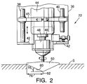
- the cutting head 22 is shown in more detail, and includes a tool mounting plate 36 supported by the Y carriage 24 with bolts (not shown) or other suitable means.
- a pair of slide rods 38, 40 are secured in a spaced relationship relative to the mounting plate 36 by upper (not shown) and lower 42 extending flanges attached to the mounting plate.
- a cutting tool drive motor 44 having a drive shaft 46 is, in turn, supported by the slide rods 38, 40 through the upper and lower 42 flanges, which are clamped to the drive motor as illustrated and slide up and down the rods. In this manner, the motor 44 is moveable substantially in a vertical, or Z coordinate, direction.
- a chuck 48 is fixed to one end of the drive shaft 46, and in turn couples a cutting tool 50 with the drive shaft, such that the motor rotates the shaft, chuck and the tool about a common axis of rotation 52.
- a vertical positioning motor 54 (FIG. 1) is also fixed to the mounting plate 36, to control the upward and downward movement and vertical position of the cutting tool drive motor 44, and thus of the cutting tool 50 coupled to the motor 44.
- the positioning motor 54 drives a lead screw (not shown), or other suitable drive linkage, that is oriented parallel to the Z coordinate direction and is supported on the mounting plate 36.
- the lead screw engages a threaded opening formed in a laterally extending portion of the upper bracket that is coupled to an upper portion of the positioning motor 54.
- the vertical positioning motor 54 is also controlled by signals received from the controller 12.
- the sheet material S is releasably held on the bed 20 of the cutting machine by variable position clamps 55, 55, but may alternatively be held by vacuum hold downs (not shown) such as are marketed by the assignee of the present invention, or other suitable means.
- a letter "I" produced in sheet material in accordance with the present invention is indicated generally by the reference numeral 56.
- the letter 56 may include a return 58, and includes an apex 60 that extends along the letter.
- the return 58 is a measure of the distance from the lowermost edge of the facets 62, 64 and a background of the sheet material S, and is essentially a "step" at which lower edges of the facets terminate.
- the return 58 is preferably constant around the letter, and may be user-selected and input via the keyboard of the controller 12.
- the letter 56 is a prismatic letter, and thus includes two beveled sides 62, 64 that generally define facets and abut along the apex 60.
- the angle of the facets relative to the sheet material S is defined by the angle, described further below, of the cutting tool 50.
- the tool passes to be followed by the cutting head and associated cutting tool for the letter 56 are illustrated in FIG. 3a at 66, 68 and 70, and the determination of these tool passes described below with respect to FIG. 4.
- the particular tool passes for a given graphic image will differ depending upon the size and style of the graphic image, as well as any return, and also upon the cutting angle and radius of the tool 50.
- the preferred method of the present invention is described, and initially includes a selection of the graphic image to be produced.
- the selection may be made, for example, by the operator through the keyboard 15 or via a graphic image generating program.
- the letter "I" is selected for production.
- the initial values for the graphic image are then input (block 72) to the computer 13 of the controller 12.
- the initial values include a predetermined set of coordinates, or other suitable information such as a set of points and vectors, that define a two-dimensional initial graphic representation of the image, the cutting tool 50 radius and cutting angle, and the desired return 58 for the image.
- the coordinates of the initial graphic representation of the letter "I" are input into the controller 12, for example after being read from a memory storage device, or a graphic images generating program, and depend upon the style and size of the image as well as the position of the image on the sheet material.
- the desired return 58 is also input, preferably via the keyboard of the controller 12, and a corresponding signal is presented to the controller.
- the maximum offset (FIG. 3a at 75) that may be used with the initial graphic representation is determined (block 74).
- the maximum offset will be negative, and corresponds to an in-line (as opposed to an outline) that is positioned within and spaced from the initial graphic representation.
- the maximum stroke width is determined by generating in-lines from the initial graphic representation.
- the maximum offset may also be determined, for example, by fitting circles within the initial graphic representation, in which case the radius of the largest circle that fits within the initial graphic representation corresponding to the maximum offset.
- an initial offset is selected that is large enough to ensure an unacceptable condition. That is, the initially selected offset should be selected which results in an in-line that does not fit within the initial graphic representation. For example, if the graphic image is roughly 45 cm by 30 cm (18" by 12,") the initial offset might be 38 cm (15"). When evaluated by software such as the "Graphix Advantage®” which is produced and sold by the assignee of the present invention, this will result in a "failure" condition.
- a subsequent offset is selected that is some fraction, for example one-half, of the previous offset.
- a signal indicative of the subsequent offset is generated, and is then evaluated to determine whether the subsequent offset fits within the initial graphic representation, and thus results in a "success” condition. If the failure condition again results, then subsequent, smaller offsets are selected and evaluated until a "success” condition results.
- a success condition indicates that the offset fits within the initial graphic representation, which in most cases means that a larger offset will result in an in-line that still fits within the initial graphic representation. Accordingly, a larger offset that resulted in the success condition must be determined. From an offset that results in a "success" condition, the next offset to be evaluated is some fraction larger than the previous, successful offset. Again, by way of example, the next offset is selected to be about halfway between the successful offset, and the most-recent offset that resulted in failure. As the steps of selecting and evaluating subsequent offsets are repeated, a value which will be the maximum offset, is converged upon.
- a signal indicative of the value of the maximum offset (OFFSET max. ) is then generated, and is stored in a memory storage device, e.g., a RAM of the computer 13, for subsequent use.
- the maximum offset is used to determine whether the sheet material is of sufficient thickness to produce the prismatic graphic image (block 82). If the sheet material is too thin, then the graphic images cannot be fully formed in the sheet material.
- the tool has a radius (R) 76, and a cutting angle 78 defined by a plane normal to the axis of rotation 52 and a cutting surface 80 of the tool.
- a signal indicative of the value of the minimum thickness T is generated and is compared, for example by a comparator (not shown separately) of the computer 13, to a signal indicative of the actual thickness of the sheet material, as is provided above via the keyboard of the controller 12, to determine whether the proposed graphic images are too big (thick) to fit within the sheet material S.
- the return 58, if any, must also be added to determine the minimum thickness.
- the controller 12 determines whether the minimum thickness T is at least equal to the sheet material thickness. If it is determined from the comparison that the minimum thickness T is at least equal to the sheet material thickness, then the graphic image is too deep for the sheet material. Accordingly, an error signal is generated by the controller 12. Given an error condition, one or more of the following must be performed: replacement of the cutting tool 50 with one having a smaller/shallower cutting angle 78, selection of a sheet material of a greater thickness or of a different graphic image having a smaller maximum offset, or some combination, after which the above described steps should be repeated to ensure compatibility of the sheet material, cutting tool and graphic images.
- the number of tool passes required to produce the graphic image is then determined (block 84) using the signal indicative of the maximum offset (OFFSET max. ). While two-dimensional tool passes are described below, those skilled in the art will recognize that three dimensional passes may be generated, for example by varying the depth of a pass as the width of the graphic image changes.
- the required number of tool passes (N) is related to the maximum depth of the cutting tool as compared to the minimum thickness T to produce the graphic images. If N is not equal to an integer, then N is rounded up to the next integer, and a corresponding signal is generated.
- the computer 13 determines the appropriate depth of each pass, and thus the change in depth per pass using signals indicative of the number of tool passes (N), the maximum offset (OFFSET max. ), the tool radius (R) 76, and the cutting angle ( ⁇ ) 78. While the change in depth between passes may differ, it is preferably constant. For example, if the minimum thickness T required to produce the graphic image is 5,3 cm (2,1 inches) and maximum depth per pass for the cutting tool is 1 cm (0,4 inch), then 6 passes will be required to produce the graphic images. The change of depth (d ch ) for each pass will be 5,3/6 (2.1/6) or about 0,88 cm (0,35 inch).
- the tool pass to be followed by the cutting tool 50, and more specifically by the axis of rotation 52, for each pass is then determined using the initial graphic representation, the OFFSET PER PASS , and the change in depth per pass d ch .
- the initial graphic representation the OFFSET PER PASS
- the change in depth per pass d ch the change in depth per pass d ch .
- a first tool pass illustrated in FIG. 3a by the line 66, includes the initial graphic representation, coupled with a depth (d 1 ) as measured from the top of the sheet material, equal to the change in depth d ch times the number of tool passes N.
- the depth (d 1 ) of the first tool pass may also be determined using the sheet material thickness and the return, if any.
- Signals corresponding to the first pass, including the depth of the first pass and the first tool pass are generated and stored in the memory storage device of the computer 13 or other suitable location for subsequent use.
- each tool pass can be expressed in various ways, such as by a coordinate set or by points and vectors.
- a second tool pass represented in FIG. 3a by the line 68, is determined generating an in-line spaced from initial graphic representation by the OFFSET PER PASS .
- the second tool pass depth (d 2 ) is shallower, as measured from the top of the sheet material S, by an amount equal to the depth per pass (d ch ).
- Signals corresponding to the second pass, including the depth of the second pass and the second tool pass, are generated and stored in the memory storage device of the computer 13 for subsequent use.
- the depth and tool pass for a subsequent pass may be determined from information defining a previous pass rather than from the initial graphic representation.
- subsequent passes including depths and tool passes are determined for N passes, and corresponding signals are generated and stored as described above.
- depth and tool pass for a subsequent pass may be determined from a previous pass rather than from the initial graphic representation.
- a V-cutter is used as the cutting tool 50 to produce the beveled sides 62, 64, and a portion of the beveled edges is formed each time the tool follows a tool pass.
- the automatic cutting machine 14 which responds by moving the cutting tool laterally, and then vertically, in accordance with the generated signals to remove material from the sheet material by following the first, second and subsequent passes to produce (block 86) the image in the sheet material.
- the passes are preferably executed from the top down, to minimize chipping and splintering of the sheet material.
- the top-down order is a more efficient use of the machine, and additionally results in less chipping in the sheet material, which may occur along the apex 60. Thus, the last pass that was determined will be the first one executed.
- An optional, final step in producing the image is to generate the return 58.
- the cutting tool 50 is typically replaced with a narrower, straight tool, which is lowered into the sheet material, and the cutting tool is moved along the tool pass 90, to remove material outside of that pass.
- three dimensional tool passes may be determined by varying the depth of the cutting tool along a tool path in proportion to the width of the graphic image at any particular point.
Landscapes
- Engineering & Computer Science (AREA)
- Human Computer Interaction (AREA)
- Manufacturing & Machinery (AREA)
- Physics & Mathematics (AREA)
- General Physics & Mathematics (AREA)
- Automation & Control Theory (AREA)
- Mechanical Engineering (AREA)
- Control Of Cutting Processes (AREA)
- Numerical Control (AREA)
Claims (7)
- Procédé de réalisation d'une image graphique prismatique se présentant sous la forme d'une plaque de matière (S) d'épaisseur prédéterminée, utilisant une machine de coupe automatique (14) sensible à des signaux de passes d'outil et comportant un outil de coupe rotatif (50) pour enlever de la matière de la plaque de matière (S), l'outil de coupe (50) ayant un axe de rotation (52), un rayon (76) s'étendant à partir de l'axe (52) jusqu'à un bord extérieur de l'outil (50), une surface de coupe (80) et un angle de coupe (78) délimité par la surface de coupe (80) et un plan perpendiculaire à l'axe (52), l'image graphique ayant une représentation graphique initiale bidimensionnelle présélectionnée (56), ledit procédé comprenant les étapes consistant à :caractérisé en ce que, pour réaliser une image graphique prismatique comportant des côtés obliques (62, 64) contigus à une ligne de crête (60) et inclinés d'un angle prédéterminé par rapport à la plaque de matière (S),engendrer des signaux (72) indicatifs d'une représentation graphique initiale (56) de l'image graphique à réaliser dans la plaque de matière (S) conformément à un programme de création d'image graphique, la représentation graphique initiale (56) étant définie par un ensemble prédéterminé de données ;déterminer un écart maximum (75) de l'image graphique conformément à la représentation graphique initiale (56) et engendrer des signaux (74) indicatifs de l'écart maximum ;déterminer des passes concentriques (66, 68, 70) de l'outil conformément aux signaux indicatifs de la représentation graphique initiale (56), aux signaux indicatifs de l'écart maximum (75), et aux signaux indicatifs du rayon (76) et de l'angle de coupe (78) de l'outil, les passes (66, 68, 70) de l'outil étant orientées d'une façon générale perpendiculairement à l'axe de rotation (52), et engendrer des signaux indicatifs des passes (66, 68, 70) de l'outil ; etenvoyer les signaux (86) indicatifs des passes (66, 68, 70) de l'outil à la machine de coupe automatique (14),a) l'angle de coupe (78) de l'outil définit l'angle des côtés obliques (62, 64) par rapport à la plaque de matière (S),b) le nombre N de passes concentriques (66, 68, 70) de l'outil est calculé en divisant l'écart maximum (75) par le rayon (76) de l'outil et en arrondissant au nombre entier directement supérieur,c) la variation de profondeur (dch) entre des passes consécutives (66, 68, 70) de l'outil (50) est calculée en multipliant l'écart par passe par la tangente de l'angle de coupe (78),d) chaque passe (66, 68, 70) que doit suivre l'outil de coupe (50) est déterminée par la représentation graphique initiale , l'écart par passe (66, 68, 70) et la variation de profondeur (dch) entre des passes consécutives (66, 68, 70).
- Procédé selon la revendication 1, comprenant en outre l'étape consistant à :
enlever de la matière (86) de la plaque de matière (S) en utilisant l'outil de coupe rotatif (50) conformément aux signaux indicatifs des passes (66, 68, 70) de l'outil pour réaliser l'image graphique dans la plaque de matière (S). - Procédé selon la revendication 1 ou 2, comprenant en outre les étapes consistant à :déterminer une profondeur minimale de l'image graphique conformément au signal indicatif de l'écart maximum (75), et aux signaux indicatifs du rayon (76) et de l'angle de coupe (78) de l'outil, et engendrer un signal indicatif de la profondeur minimale ;introduire un signal indicatif de l'épaisseur prédéterminée de la plaque de matière (S) ;comparer le signal indicatif de la profondeur minimale et le signal indicatif de l'épaisseur prédéterminée, etindiquer un état d'erreur si celle-ci est établie pendant l'étape consistant à déterminer si la profondeur minimale de l'image graphique est supérieure ou égale à l'épaisseur prédéterminée.
- Procédé selon l'une quelconque des revendications 1 à 3, dans lequel l'étape consistant à déterminer l'écart maximum (75) de l'image graphique comprend les étapes consistant à :déterminer une ligne de contour intermédiaire de l'image graphique conformément à la représentation graphique initiale (56) et un signal indicatif d'un écart initial prédéterminé, et engendrer des signaux indicatifs de la ligne de contour intermédiaire ; etévaluer les signaux indicatifs de la ligne de contour intermédiaire conformément aux signaux indicatifs de la représentation graphique initiale (56) pour déterminer si l'écart est l'écart maximum (75).
- Procédé selon la revendication 4, comprenant en outre les étapes consistant à :
régler l'écart pour régler la ligne de contour intermédiaire correspondante s'il est déterminé pendant l'étape consistant à évaluer que l'écart n'est pas égal à l'écart maximum (75) pour la représentation graphique initiale (56). - Article constitué par un panneau, doté d'une image graphique prismatique, se présentant sous la forme d'une plaque de matière (S) d'épaisseur prédéterminée, réalisé en utilisant une machine de coupe (14) qui est sensible à des signaux de passes d'outil et qui comporte un outil de coupe rotatif (50) pour enlever de la matière de la plaque de matière (S), l'outil de coupe (50) ayant un axe de rotation (52), un rayon (76) mesuré perpendiculairement à l'axe (52) et allant jusqu'à un bord extérieur de l'outil (50), une surface de coupe (80) et un angle de coupe (78) délimité par la surface de coupe (80) et un plan perpendiculaire à l'axe (52), l'image graphique ayant une représentation graphique initiale bidimensionnelle présélectionnée (56), l'article étant réalisé conformément à un procédé selon l'une quelconque des revendications 1 à 5.
- Appareil (10) pour commander une machine de coupe automatique (14) en vue de réaliser une image graphique prismatique dans une plaque de matière (S) d'épaisseur prédéterminée, la machine de coupe automatique (14) étant sensible à des signaux de passes d'outil et comportant un outil de coupe rotatif (50) pour enlever de la matière de la plaque de matière (S), l'outil de coupe (50) ayant un axe de rotation (52), un rayon (76) s'étendant de l'axe (52) jusqu'à un bord extérieur de l'outil (50), une surface de coupe (80) et un angle de coupe (78) délimité par la surface de coupe (80) et un plan perpendiculaire à l'axe (52), l'image graphique ayant une représentation graphique initiale bidimensionnelle présélectionnée (56), l'appareil comprenant :caractérisé par des moyens pour réaliser une image graphique prismatique comportant des côtés obliques (62, 64) contigus à une ligne de crête (60) et inclinés par rapport à la plaque de matière (S) d'un angle prédéterminé défini par l'angle de coupe (78) de l'outil, lesdits moyens comprenant :des moyens (13) pour engendrer des signaux indicatifs d'une représentation graphique initiale (56) de l'image graphique à réaliser dans la plaque de matière conformément à un programme de création d'image graphique, la représentation graphique initiale (56) étant définie par un ensemble prédéterminé de données ;des moyens (12) pour déterminer un écart maximum (75) de l'image graphique conformément à la représentation graphique initiale (56) et pour engendrer des signaux indicatifs de l'écart maximum (75) ;des moyens (12) pour déterminer des passes (66, 68, 70) de l'outil conformément aux signaux indicatifs de la représentation graphique initiale (56), au signal indicatif de l'écart maximum (75) et aux signaux indicatifs du rayon (76) et de l'angle de coupe (78) de l'outil, les passes (66, 68, 70) de l'outil étant orientées sensiblement perpendiculairement à l'axe de rotation (52) , et pour engendrer des signaux indicatifs des passes (66, 68, 70) de l'outil ; etdes moyens (16) pour envoyer les signaux indicatifs des passes (66, 68, 70) de l'outil à la machine de coupe automatique (14),a) des moyens (84) pour calculer le nombre N de passes concentriques (66, 68, 70) de l'outil en divisant l'écart maximum (75) par le rayon (76) de l'outil et en arrondissant au nombre entier directement supérieur,b) des moyens (84) pour calculer la variation de profondeur (dch) entre des passes consécutives (66, 68, 70) de l'outil (50) en multipliant l'écart par passe par la tangente de l'angle de coupe (78),c) des moyens (86) pour commander chaque passe (66, 68, 70) que doit suivre l'outil de coupe conformément à la représentation graphique initiale (56), à l'écart par passe (66, 68, 70) et à la variation de profondeur (dch) entre des passes consécutives (66, 68, 70).
Applications Claiming Priority (2)
| Application Number | Priority Date | Filing Date | Title |
|---|---|---|---|
| US08/434,388 US5575099A (en) | 1995-05-03 | 1995-05-03 | Method and apparatus for producing signs with prismatic letters and graphic images |
| US434388 | 1995-05-03 |
Publications (2)
| Publication Number | Publication Date |
|---|---|
| EP0741347A1 EP0741347A1 (fr) | 1996-11-06 |
| EP0741347B1 true EP0741347B1 (fr) | 2000-08-16 |
Family
ID=23724027
Family Applications (1)
| Application Number | Title | Priority Date | Filing Date |
|---|---|---|---|
| EP96106365A Expired - Lifetime EP0741347B1 (fr) | 1995-05-03 | 1996-04-23 | Méthode et appareil pour produire des signes avec des lettres prismatiques et des images graphiques |
Country Status (8)
| Country | Link |
|---|---|
| US (1) | US5575099A (fr) |
| EP (1) | EP0741347B1 (fr) |
| JP (1) | JP2963389B2 (fr) |
| KR (1) | KR100222372B1 (fr) |
| AU (1) | AU679658B2 (fr) |
| CA (1) | CA2175539C (fr) |
| DE (1) | DE69609761T2 (fr) |
| MY (1) | MY112639A (fr) |
Families Citing this family (19)
| Publication number | Priority date | Publication date | Assignee | Title |
|---|---|---|---|---|
| CA1339155C (fr) | 1987-07-28 | 1997-07-29 | David M. Dundorf | Enseignes gravees par ordinateur et methode et appareil de production deces enseignes |
| DE69619789T2 (de) * | 1995-09-28 | 2002-08-29 | THE INSTITUTE OF PHYSICAL & CHEMICAL RESEARCH, WAKO | Methode zum Bearbeiten mit hoher Geschwindigkeit von Matrizen und Ultrahochgeschwindigkeitsfräsmaschine |
| US5697413A (en) * | 1996-06-04 | 1997-12-16 | Fuller; Maurice D. | Method and machine for fabricating a decorative inlaid floor |
| US5936862A (en) * | 1997-05-19 | 1999-08-10 | Dogbyte Development | Computer program for generating picture frames |
| US6506324B1 (en) | 2000-03-27 | 2003-01-14 | Gerber Scientific Products, Inc. | Method for embossing a sheet-type work material |
| US6689035B1 (en) | 2000-04-11 | 2004-02-10 | Gerber Scientific Products, Inc. | Method and apparatus for designing and creating a package |
| US6722249B2 (en) * | 2001-11-06 | 2004-04-20 | Rodel Holdings, Inc | Method of fabricating a polishing pad having an optical window |
| US20040231211A1 (en) * | 2003-05-02 | 2004-11-25 | Johnson John R. | Three-dimensional automobile badge |
| US6950713B2 (en) * | 2003-07-30 | 2005-09-27 | Greenwood, Inc. | Method for creating a three-dimensional engraving in a solid and a product created by said method |
| GB2436079A (en) * | 2006-03-16 | 2007-09-19 | Guy Satchwell | Method of manufacturing three-dimensional signage |
| ITTA20100010A1 (it) * | 2010-08-13 | 2012-02-14 | Planet Comm Di Ricci Salvatore | Componente per insegna, metodo di realizzazione, annesso apparato luminoso, produzione finale di insegna. |
| US9026242B2 (en) * | 2011-05-19 | 2015-05-05 | Taktia Llc | Automatically guided tools |
| US10556356B2 (en) | 2012-04-26 | 2020-02-11 | Sharper Tools, Inc. | Systems and methods for performing a task on a material, or locating the position of a device relative to the surface of the material |
| CN103575507A (zh) * | 2012-08-10 | 2014-02-12 | 北京京东方光电科技有限公司 | 一种3d显示产品的光学检测方法及系统 |
| US11131980B2 (en) * | 2013-02-20 | 2021-09-28 | Cricut, Inc. | Electronic cutting machine |
| JP6464562B2 (ja) * | 2014-03-26 | 2019-02-06 | 日本電気株式会社 | 過加工防止モデル生成装置、数値命令演算装置、および表面加工装置 |
| EP3294503B1 (fr) | 2015-05-13 | 2020-01-29 | Shaper Tools, Inc. | Systèmes, procédés et appareil pour outils guidés |
| CN109643098B (zh) | 2016-08-19 | 2022-06-03 | 整形工具股份有限公司 | 一种用于跟踪钻机的使用的系统、方法及介质 |
| US11400614B2 (en) * | 2017-04-05 | 2022-08-02 | Zünd Systemtechnik Ag | Cutting machine with overview camera |
Family Cites Families (26)
| Publication number | Priority date | Publication date | Assignee | Title |
|---|---|---|---|---|
| USRE25930E (en) * | 1965-12-07 | Recording and reproducing the shape of three-dimensional objects | ||
| US3213757A (en) * | 1964-03-23 | 1965-10-26 | Jr William T Cardwell | Double bipolar photosculpture |
| US3635124A (en) * | 1969-10-20 | 1972-01-18 | John T Parsons | Use of tape-controlled milling machines to carve combustible casting patterns |
| US3650178A (en) * | 1970-01-08 | 1972-03-21 | Joe S Appleton | Multi-purpose multi-motion machine tool |
| US3690200A (en) * | 1970-12-24 | 1972-09-12 | Automatic Control Systems Inc | Machine control utilizing a plurality of control templates and tracer mechanisms |
| US3857025A (en) * | 1971-05-07 | 1974-12-24 | Remington Arms Co Inc | Numerically controlled engraving machine system |
| DE2239568A1 (de) * | 1972-08-11 | 1974-02-28 | Jochen Klaar | Vorrichtung zur spanenden bearbeitung von trochoidenfoermigen innenwaenden, insbesondere fuer die zylinder von wankelmotoren |
| US3843875A (en) * | 1973-03-07 | 1974-10-22 | Remington Arms Co Inc | Numerical control checkering system |
| US3915061A (en) * | 1973-05-07 | 1975-10-28 | John H Stockman | Method for engraving graphical representations upon workable materials |
| US3968728A (en) * | 1975-08-08 | 1976-07-13 | Goldfarb Adolph E | Carving tool |
| US4025764A (en) * | 1976-03-17 | 1977-05-24 | Alfred Tack | Multi pass machining with control of feed increments |
| US4096770A (en) * | 1977-06-06 | 1978-06-27 | Cincinnati Milacron Inc. | Method and apparatus for modifying the position of a machine slide to compensate for different following errors |
| US4173786A (en) * | 1977-06-23 | 1979-11-06 | Cincinnati Milacron Inc. | Method and apparatus for cutting a thread on a rotating workpiece |
| GB2043300A (en) * | 1979-02-19 | 1980-10-01 | Couzens G H R | Engraving apparatus and method |
| US4455113A (en) * | 1981-09-11 | 1984-06-19 | Namecraft Manufacturing Corp. | Method of producing grouped symbols |
| CA1204315A (fr) * | 1984-02-08 | 1986-05-13 | Pratt & Whitney Canada Inc. | Fraisage en train multipasse |
| US4624609A (en) * | 1985-03-05 | 1986-11-25 | Pickett David R | Apparatus for milling sign cutouts and letters from templates |
| JPS63263501A (ja) * | 1987-04-21 | 1988-10-31 | Fanuc Ltd | 曲面加工用のncデ−タ作成方法 |
| US5197013A (en) * | 1987-07-28 | 1993-03-23 | David M. Dundorf | Method of forming a carved sign using an axially rotating carving tool |
| JPH01303504A (ja) * | 1988-05-31 | 1989-12-07 | Fanuc Ltd | 複合曲面切削パス生成方法 |
| US4878524A (en) * | 1988-06-13 | 1989-11-07 | Kohler General Corp. | Woodworking machine having a plurality of sequentially operative multiple tool units |
| US5033005A (en) * | 1988-09-06 | 1991-07-16 | Schlumberger Technologies, Inc. | Analytical computer-aided machining system and method |
| JPH0716816B2 (ja) * | 1989-12-08 | 1995-03-01 | 三菱電機株式会社 | ネジ切り方法 |
| US5246319A (en) * | 1992-08-19 | 1993-09-21 | Prince Lawrence R | Method and apparatus for creating tool path data for a numerically controlled cutter to create incised carvings |
| US5454422A (en) * | 1992-10-29 | 1995-10-03 | Kitagawa Kogyo Co., Ltd. | Woodworking machines |
| US5424845A (en) * | 1993-02-25 | 1995-06-13 | Ohio Electronic Engravers, Inc. | Apparatus and method for engraving a gravure printing cylinder |
-
1995
- 1995-05-03 US US08/434,388 patent/US5575099A/en not_active Expired - Lifetime
-
1996
- 1996-04-23 EP EP96106365A patent/EP0741347B1/fr not_active Expired - Lifetime
- 1996-04-23 DE DE69609761T patent/DE69609761T2/de not_active Expired - Fee Related
- 1996-04-23 MY MYPI96001542A patent/MY112639A/en unknown
- 1996-05-01 CA CA002175539A patent/CA2175539C/fr not_active Expired - Fee Related
- 1996-05-02 AU AU52033/96A patent/AU679658B2/en not_active Ceased
- 1996-05-03 KR KR1019960014367A patent/KR100222372B1/ko not_active Expired - Fee Related
- 1996-05-07 JP JP8112846A patent/JP2963389B2/ja not_active Expired - Fee Related
Also Published As
| Publication number | Publication date |
|---|---|
| CA2175539A1 (fr) | 1996-11-04 |
| EP0741347A1 (fr) | 1996-11-06 |
| US5575099A (en) | 1996-11-19 |
| AU679658B2 (en) | 1997-07-03 |
| KR960042428A (ko) | 1996-12-21 |
| DE69609761T2 (de) | 2001-04-12 |
| DE69609761D1 (de) | 2000-09-21 |
| MY112639A (en) | 2001-07-31 |
| JPH091442A (ja) | 1997-01-07 |
| JP2963389B2 (ja) | 1999-10-18 |
| CA2175539C (fr) | 1999-03-30 |
| KR100222372B1 (ko) | 1999-10-01 |
| AU5203396A (en) | 1996-11-14 |
Similar Documents
| Publication | Publication Date | Title |
|---|---|---|
| EP0741347B1 (fr) | Méthode et appareil pour produire des signes avec des lettres prismatiques et des images graphiques | |
| JP5094580B2 (ja) | 工作物を加工するための装置及び方法 | |
| US4749347A (en) | Topology fabrication apparatus | |
| US7241981B2 (en) | Systems and methods for displaying images and processing work pieces | |
| EP1298507B1 (fr) | Procédé pour fixer la vitesse d'avance d'un outil et une machine-outil utilisant cette méthode | |
| JPH02116497A (ja) | シート切断機 | |
| JPH04507069A (ja) | 光学レンズの縁加工方法および装置 | |
| GB2206513A (en) | Groove forming machine tool | |
| US7340321B2 (en) | Method and device for milling freeform surfaces | |
| GB2043300A (en) | Engraving apparatus and method | |
| US3827334A (en) | Numerically controlled engraving machine system | |
| JP4009237B2 (ja) | 半導体cmp加工用パッドの細溝加工機械 | |
| EP0919893A2 (fr) | Machine d'usinage avec appareil à commande numérique | |
| JP4507318B2 (ja) | 裁断機 | |
| JP2677819B2 (ja) | V字形状溝加工機 | |
| JPS6062448A (ja) | 倣い制御方法 | |
| US5562134A (en) | Woodworking machine | |
| EP0833715B1 (fr) | Formation de dents pour lame de scie | |
| JP4256226B2 (ja) | カッティングプロッタの円切断方法 | |
| KR100928649B1 (ko) | 다이아몬드 스핀 크로스 컷팅장치 및 그 사용방법 | |
| JP2677820B2 (ja) | V字形状溝加工機を用いた中間折曲製品の加工方法 | |
| CN119794822B (zh) | 一种多轴复合加工机床 | |
| JP2020110863A (ja) | 切削加工方法及び切削加工装置並びにプレス成形用金型 | |
| CA1298689C (fr) | Dispositif de fabrication de structures topologiques | |
| CN117822305B (zh) | 一种裁床的裁切刀组件及裁床 |
Legal Events
| Date | Code | Title | Description |
|---|---|---|---|
| PUAI | Public reference made under article 153(3) epc to a published international application that has entered the european phase |
Free format text: ORIGINAL CODE: 0009012 |
|
| 17P | Request for examination filed |
Effective date: 19960423 |
|
| AK | Designated contracting states |
Kind code of ref document: A1 Designated state(s): DE FR GB IT |
|
| RBV | Designated contracting states (corrected) |
Designated state(s): DE FR GB IT |
|
| 17Q | First examination report despatched |
Effective date: 19971015 |
|
| GRAG | Despatch of communication of intention to grant |
Free format text: ORIGINAL CODE: EPIDOS AGRA |
|
| GRAG | Despatch of communication of intention to grant |
Free format text: ORIGINAL CODE: EPIDOS AGRA |
|
| GRAH | Despatch of communication of intention to grant a patent |
Free format text: ORIGINAL CODE: EPIDOS IGRA |
|
| GRAH | Despatch of communication of intention to grant a patent |
Free format text: ORIGINAL CODE: EPIDOS IGRA |
|
| GRAA | (expected) grant |
Free format text: ORIGINAL CODE: 0009210 |
|
| AK | Designated contracting states |
Kind code of ref document: B1 Designated state(s): DE FR GB IT |
|
| REF | Corresponds to: |
Ref document number: 69609761 Country of ref document: DE Date of ref document: 20000921 |
|
| ITF | It: translation for a ep patent filed | ||
| ET | Fr: translation filed | ||
| PLBE | No opposition filed within time limit |
Free format text: ORIGINAL CODE: 0009261 |
|
| STAA | Information on the status of an ep patent application or granted ep patent |
Free format text: STATUS: NO OPPOSITION FILED WITHIN TIME LIMIT |
|
| 26N | No opposition filed | ||
| REG | Reference to a national code |
Ref country code: GB Ref legal event code: IF02 |
|
| REG | Reference to a national code |
Ref country code: GB Ref legal event code: 732E |
|
| PGFP | Annual fee paid to national office [announced via postgrant information from national office to epo] |
Ref country code: IT Payment date: 20060430 Year of fee payment: 11 |
|
| PG25 | Lapsed in a contracting state [announced via postgrant information from national office to epo] |
Ref country code: IT Free format text: LAPSE BECAUSE OF NON-PAYMENT OF DUE FEES Effective date: 20070423 |
|
| PGFP | Annual fee paid to national office [announced via postgrant information from national office to epo] |
Ref country code: FR Payment date: 20090817 Year of fee payment: 14 |
|
| PGFP | Annual fee paid to national office [announced via postgrant information from national office to epo] |
Ref country code: GB Payment date: 20090727 Year of fee payment: 14 Ref country code: DE Payment date: 20090729 Year of fee payment: 14 |
|
| GBPC | Gb: european patent ceased through non-payment of renewal fee |
Effective date: 20100423 |
|
| REG | Reference to a national code |
Ref country code: FR Ref legal event code: ST Effective date: 20101230 |
|
| PG25 | Lapsed in a contracting state [announced via postgrant information from national office to epo] |
Ref country code: DE Free format text: LAPSE BECAUSE OF NON-PAYMENT OF DUE FEES Effective date: 20101103 |
|
| PG25 | Lapsed in a contracting state [announced via postgrant information from national office to epo] |
Ref country code: GB Free format text: LAPSE BECAUSE OF NON-PAYMENT OF DUE FEES Effective date: 20100423 |
|
| PG25 | Lapsed in a contracting state [announced via postgrant information from national office to epo] |
Ref country code: FR Free format text: LAPSE BECAUSE OF NON-PAYMENT OF DUE FEES Effective date: 20100430 |