EP0742073A2 - Centre d'usinage avec un dispositif de changement des pièces - Google Patents
Centre d'usinage avec un dispositif de changement des pièces Download PDFInfo
- Publication number
- EP0742073A2 EP0742073A2 EP96102433A EP96102433A EP0742073A2 EP 0742073 A2 EP0742073 A2 EP 0742073A2 EP 96102433 A EP96102433 A EP 96102433A EP 96102433 A EP96102433 A EP 96102433A EP 0742073 A2 EP0742073 A2 EP 0742073A2
- Authority
- EP
- European Patent Office
- Prior art keywords
- loading
- machine
- workpiece
- workpieces
- center according
- Prior art date
- Legal status (The legal status is an assumption and is not a legal conclusion. Google has not performed a legal analysis and makes no representation as to the accuracy of the status listed.)
- Granted
Links
Images


Classifications
-
- B—PERFORMING OPERATIONS; TRANSPORTING
- B23—MACHINE TOOLS; METAL-WORKING NOT OTHERWISE PROVIDED FOR
- B23Q—DETAILS, COMPONENTS, OR ACCESSORIES FOR MACHINE TOOLS, e.g. ARRANGEMENTS FOR COPYING OR CONTROLLING; MACHINE TOOLS IN GENERAL CHARACTERISED BY THE CONSTRUCTION OF PARTICULAR DETAILS OR COMPONENTS; COMBINATIONS OR ASSOCIATIONS OF METAL-WORKING MACHINES, NOT DIRECTED TO A PARTICULAR RESULT
- B23Q41/00—Combinations or associations of metal-working machines not directed to a particular result according to classes B21, B23, or B24
- B23Q41/08—Features relating to maintenance of efficient operation
-
- B—PERFORMING OPERATIONS; TRANSPORTING
- B23—MACHINE TOOLS; METAL-WORKING NOT OTHERWISE PROVIDED FOR
- B23Q—DETAILS, COMPONENTS, OR ACCESSORIES FOR MACHINE TOOLS, e.g. ARRANGEMENTS FOR COPYING OR CONTROLLING; MACHINE TOOLS IN GENERAL CHARACTERISED BY THE CONSTRUCTION OF PARTICULAR DETAILS OR COMPONENTS; COMBINATIONS OR ASSOCIATIONS OF METAL-WORKING MACHINES, NOT DIRECTED TO A PARTICULAR RESULT
- B23Q11/00—Accessories fitted to machine tools for keeping tools or parts of the machine in good working condition or for cooling work; Safety devices specially combined with or arranged in, or specially adapted for use in connection with, machine tools
- B23Q11/08—Protective coverings for parts of machine tools; Splash guards
-
- B—PERFORMING OPERATIONS; TRANSPORTING
- B23—MACHINE TOOLS; METAL-WORKING NOT OTHERWISE PROVIDED FOR
- B23Q—DETAILS, COMPONENTS, OR ACCESSORIES FOR MACHINE TOOLS, e.g. ARRANGEMENTS FOR COPYING OR CONTROLLING; MACHINE TOOLS IN GENERAL CHARACTERISED BY THE CONSTRUCTION OF PARTICULAR DETAILS OR COMPONENTS; COMBINATIONS OR ASSOCIATIONS OF METAL-WORKING MACHINES, NOT DIRECTED TO A PARTICULAR RESULT
- B23Q7/00—Arrangements for handling work specially combined with or arranged in, or specially adapted for use in connection with, machine tools, e.g. for conveying, loading, positioning, discharging, sorting
- B23Q7/04—Arrangements for handling work specially combined with or arranged in, or specially adapted for use in connection with, machine tools, e.g. for conveying, loading, positioning, discharging, sorting by means of grippers
-
- B—PERFORMING OPERATIONS; TRANSPORTING
- B23—MACHINE TOOLS; METAL-WORKING NOT OTHERWISE PROVIDED FOR
- B23Q—DETAILS, COMPONENTS, OR ACCESSORIES FOR MACHINE TOOLS, e.g. ARRANGEMENTS FOR COPYING OR CONTROLLING; MACHINE TOOLS IN GENERAL CHARACTERISED BY THE CONSTRUCTION OF PARTICULAR DETAILS OR COMPONENTS; COMBINATIONS OR ASSOCIATIONS OF METAL-WORKING MACHINES, NOT DIRECTED TO A PARTICULAR RESULT
- B23Q7/00—Arrangements for handling work specially combined with or arranged in, or specially adapted for use in connection with, machine tools, e.g. for conveying, loading, positioning, discharging, sorting
- B23Q7/14—Arrangements for handling work specially combined with or arranged in, or specially adapted for use in connection with, machine tools, e.g. for conveying, loading, positioning, discharging, sorting co-ordinated in production lines
- B23Q7/1405—Arrangements for handling work specially combined with or arranged in, or specially adapted for use in connection with, machine tools, e.g. for conveying, loading, positioning, discharging, sorting co-ordinated in production lines with a series disposition of similar working devices
Definitions
- the present invention relates to a machine center with at least one machine tool, each of which has a work space accessible through an operator door for machining workpieces, a loading / unloading station for the workpieces and a loading device that moves the workpieces between the loading / unloading station and the respective machine tool transported and replaced on the machine tool.
- Such machine centers are generally known.
- the loading devices are arranged in front of the respective machine tools, which are set up next to one another either in a straight line or in a circle.
- the loading device has a device that moves back and forth between the loading / unloading station and the respective machine tool and thereby transports workpieces. In this way, a larger number of machine tools can be loaded via a single loading / unloading station, at which the workpieces to be machined are entered and the finished workpieces are removed again.
- the loading device often works at the level of the operator door and changes the workpieces through it on the machine tool.
- the operator door is also required for set-up and service purposes, i.e. for maintenance, for exchanging tools, for re-measuring tools or certain geometry factors, etc.
- this object is achieved in that the loading device is arranged below the working space of the machine tool.
- the object underlying the invention is completely achieved in this way.
- the inventors of the present application have recognized that the loading device can thus be placed under the work surface of the machine tool, so that the operator door is now free again for set-up and service work, repair measures, etc. This also means that all other machine tools of the new machine center can continue to be operated by the loading device without there being any danger to the operator.
- the loading device is arranged below the working space of the machine tool, it is automatically almost completely within the outer contour, that is, the cladding of the machine tool or the machine center, so that the space required for the machine center is also reduced.
- the respective machine tool has a load space in front of its respective machine base, which carries a workpiece table arranged in the respective work area, in which the loading device is preferably arranged within a panel of the machine tool.
- the advantage here is that the loading device is arranged on the one hand in a space-saving manner in a space that is either present in machine tools or can be readily provided.
- the fact that the loading device is possibly inside the casing of the machine tool ensures particularly safe protection for the operator who is working on a machine tool that the loading device is currently driving past in order to move a machine tool downstream of the e.g. machine tool under repair.
- the loading space is connected to the respective working space through a respective loading opening, through which the loading device exchanges the workpieces.
- This measure is particularly advantageous with regard to the functional safety of the machine center, because the work area of the respective machine tool is not entirely free towards the load space, but is only connected to it by a loading opening, so that chips, drilling water used during machining of the workpieces, are used etc. affect the charger only slightly. If the loading opening is geometrically favorable and arranged, this contamination of the loading device can be kept very low.
- the loading opening is assigned a cover which is opened to replace a workpiece.
- the cover is mechanically and / or electrically / electronically locked when the operator door is open.
- This measure once again increases work safety for the operator, because it prevents the loading device from engaging in the work area of a machine tool on which an operator is currently working e.g. to exchange tools.
- This locking can either be purely mechanical, so that an open operator door by a mechanical stop and the like. prevents the sequencer from opening the cover of the loading opening. If necessary, further measures are provided to prevent the loading device from trying to replace a workpiece through a closed loading opening.
- control means provided for opening the cover are blocked by the sequence control as soon as the operator door is opened.
- the charging device has a charger which can be moved along a guide rail which is preferably profiled in cross section and which serves as a workpiece changer.
- the charger has a drive unit that automatically moves along the guide rail.
- This measure is also advantageous from a design point of view, because in order to move the charger between the machine tools and the loading / unloading station, no chains, belts or similar means are required, which are otherwise frequently used in machine tools.
- the charger is therefore a self-propelled workpiece changer, so to speak.
- the charger has a swivel arm which is folded in when the charger is being moved and which is at least partially pivoted into the work space through the loading opening when changing the workpiece.
- the advantage here is that the charging device takes up little space, the charger is folded up during the process, so to speak, so that the charging device can be arranged in a very small space below the working space of the machine tools.
- a double gripper for workpieces is arranged on the swivel arm.
- the workpiece can be changed very quickly, namely the double gripper detects the workpiece that has just been machined and exchanges it for a workpiece to be machined in a single movement, whereupon the swivel arm is folded back into the loading space.
- This very fast workpiece change leads to the further advantage that more machine tools can be arranged side by side in the new machine center, since the loading device can now operate more other machine tools within the usual machining time that one of the machine tools needs to machine the workpiece that has just been inserted.
- the workpieces are clamped in workpiece holders which are exchanged in device holders which are located in the respective working space of the respective machine tool.
- the loading / unloading station comprises a clamping station at which the workpieces in the workpiece holders are exchanged.
- this measure is advantageous from a design point of view, because the new machine center can now be operated fully automatically, so to speak.
- Another advantage of this measure is that the new machine center only requires two more workpiece holders than machine tools in the machine center.
- the one additional workpiece holder is located in the clamping station and is provided with a new workpiece, while the second additional workpiece holder is located on the charger and is exchanged for another workpiece holder with a finished workpiece on the machine tool.
- the loading device then changes e.g. a still unworked workpiece into a first machine tool and thereby takes over a workpiece machined here, which is then exchanged on a second machine tool, a workpiece being taken over there which has now already been subjected to two operations.
- This workpiece can then be exchanged on a third machine tool for a workpiece that has already been processed there, etc.
- the advantages of the new machine center are, on the one hand, that the loading device arranged under the workrooms can continue to be operated even when one or more of the machine tools are being serviced.
- the loading device then travels beneath these machine tools, which are currently not operational, and only operates the other machine tools of the machine center. Because the loading device is now arranged in the separate loading space, the greatest possible occupational safety of the operator is also ensured.
- the special design of the loading area and the loading device further ensure that the loading device is protected against dirt, etc. and only accesses the working area of a machine tool when the operator door is closed. This increases work safety and, on the other hand, the functional safety of the loading device.
- workpiece holders and one self-propelled workpiece changer is also provided for a very quick workpiece change with little design effort and with little material, so that the number of machine tools per machine center can be selected relatively high at low cost.
- the cover has a hinged cover which is arranged essentially vertically in the closed state and which is partially covered by a substantially horizontally extending sliding cover.
- FIG. 1 shows a front view of a machine center 10, in which machine tools 11, 12 and 13 (only indicated) are arranged next to one another. These machine tools 11, 12, 13 can either be set up in a straight line or in a circle. In addition to the machine tools 11, 12 and 13, a loading / unloading station 14 is provided.
- the machine tools 11, 12, 13 have a covering 15 completely surrounding them, in which an operator door 16 is provided in each machine tool 11, 12, 13, through which an operator has access to a work space 17. Setup and service measures are carried out on the individual machine tools 11, 12, 13 through this operator door 16.
- a clamping station 18 which is indicated only schematically and in which individual workpiece holders 19 are provided with workpieces 21 to be machined.
- the workpiece holders 19 thus provided with workpieces 21 are transported by means of a loading device 22 to the individual machine tools 11, 12, 13 and are exchanged and processed there in the respective work space 16.
- the finished workpieces 21 are with their Workpiece holders 19 are transported from the work rooms 17 back to the clamping station 18, where they are exchanged for new workpieces 21 to be machined.
- the loading device 22 is arranged in a loading space 25, which is located below the working spaces 17 of the machine tools 11, 12, 13 and preferably inside the casing 15.
- a charger 26 runs back and forth along a guide rail 27 and thereby transports the workpiece holders 19 containing the workpieces 21 between the clamping station 18 and the working spaces 17.
- the operator doors 16 of the machine tools 11, 12, 13 are accessible to operators at all times without being endangered by the charger 26 possibly passing by.
- FIG. 2 shows a cross-section through the machine tool 12 in a sectional illustration along the line II-II from FIG. 1, a spindle head 29 being indicated, which is provided for machining the workpieces in the working space 17.
- the machine tool 12 comprises a machine base 31, on which a schematically indicated workpiece table 32 is provided, which so to speak spans a work surface 33 in the work space 17.
- a device holder 34 is arranged, which is equipped to grip the workpiece holder 19 and to hold it during machining by tools in the spindle head 29.
- 19 ' denotes a workpiece holder which holds a finished machined workpiece, the workpiece holder 19' only being indicated schematically by a circle.
- FIG. 2 it can be clearly seen that in the illustration there the load space 25 is arranged to the left of the machine base 31, which is located below the work space 17 and at least partially below the work surface 33. Furthermore, it can be clearly seen that the load space 25 is arranged in cross section within the casing 15.
- the loading space 25 is connected to the working space 17 through a loading opening 36.
- a cover 37 is provided, which is closed by tools in the work space 17 during the machining of the workpieces, so that no contaminants get into the load space 25.
- the cover 37 is formed in two parts and comprises a sliding cover 38, which points upwards in FIG. 2 and is inclined towards the work surface 33, and a hinged cover 39, which extends approximately perpendicular to the work surface 33 and can be folded towards it . It can be seen that the sliding cover 38 engages over the hinged cover 39, so that drilling water splashing around, flying workpiece chips etc. cannot pass between the sliding cover 38 and the hinged cover 39 into the loading space 25.
- the cover 37 is locked to the operator door 16 such that the cover 37 can only be opened when the operator door 16 closed is. In this way it is ensured that an operator working in the work space 17 on the machine tool 12 cannot turn injured due to a sudden workpiece change. Should the operator door 16 be open, rather appropriate control measures ensure that the charger 26 drives past this machine tool and operates the next machine tool, so that the failure of a machine tool in the machine center 10 does not lead to the complete failure of the machine center. Seen from the loading / unloading station 14, machine tools located downstream of the machine tool that is currently under maintenance can thus be supplied with new workpieces by the loading device 22.
- This charger 26 is, so to speak, a self-propelled workpiece changer 40 which has a drive unit 41 with a motor 42 which engages on the guide rail 27 and which suitably ensures that the charger 26 can be moved along the guide rail 27 which is preferably profiled in cross section.
- the movable workpiece changer 40 also has a swivel arm 43 which is fastened to it in a foldable or slidable manner and is folded in in FIG. 3 so that it is located in the loading space 25.
- a rotatable double gripper 44 is arranged, which carries a workpiece holder 19 on one hand while the other hand is still free.
- Fig. 3 it can be clearly seen that the charger 26 is compactly folded in the position shown, so that the loader space 25 can be arranged in front of the machine base 31 and below the working space 17 without the outer contour of the machine tool having to be changed significantly.
- FIG. 3 also shows a conventional cable drag 45, which provides electrical, pneumatic and possibly hydraulic connections 46 for the charger 26 and connects them to the associated control unit / operator console 23 via the connections 46.
- a workpiece table 47 arranged behind the folding cover 39 can also be seen, which e.g. can support an abutment to better center clamped workpieces.
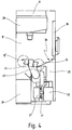
- the swivel arm 43 has been pivoted or extended through the loading opening 36 into the working space 17, where the double gripper 44 has already gripped the workpiece holder 19 'which carries a workpiece, that has already been processed by the machine tool 11.
- the workpiece holder 19 and the workpiece holder 19 ' are now replaced by a pivoting movement in the plane of FIG. 4 by 180 °, so that the device holder 34 which can be seen in FIG. 2 can take over the workpiece holder 19 with the still unprocessed workpiece.
- the swivel arm 43 is folded in or retracted so that the position shown in FIG. 3 is assumed.
Landscapes
- Engineering & Computer Science (AREA)
- Mechanical Engineering (AREA)
- Auxiliary Devices For Machine Tools (AREA)
- Feeding Of Workpieces (AREA)
- Turning (AREA)
- Multi-Process Working Machines And Systems (AREA)
Applications Claiming Priority (2)
| Application Number | Priority Date | Filing Date | Title |
|---|---|---|---|
| DE19516849A DE19516849C2 (de) | 1995-05-11 | 1995-05-11 | Maschinenzentrum mit Werkzeugmaschinen und einer Ladevorrichtung |
| DE19516849 | 1996-05-11 |
Publications (3)
| Publication Number | Publication Date |
|---|---|
| EP0742073A2 true EP0742073A2 (fr) | 1996-11-13 |
| EP0742073A3 EP0742073A3 (fr) | 1998-07-01 |
| EP0742073B1 EP0742073B1 (fr) | 2001-04-25 |
Family
ID=7761368
Family Applications (1)
| Application Number | Title | Priority Date | Filing Date |
|---|---|---|---|
| EP96102433A Expired - Lifetime EP0742073B1 (fr) | 1995-05-11 | 1996-02-17 | Centre d'usinage avec un dispositif de changement des pièces |
Country Status (5)
| Country | Link |
|---|---|
| US (3) | US5871326A (fr) |
| EP (1) | EP0742073B1 (fr) |
| JP (1) | JPH08309645A (fr) |
| DE (2) | DE19516849C2 (fr) |
| ES (1) | ES2157357T3 (fr) |
Cited By (3)
| Publication number | Priority date | Publication date | Assignee | Title |
|---|---|---|---|---|
| WO1999050020A1 (fr) * | 1998-03-16 | 1999-10-07 | Quintax Machine Tools Ab | Machine-outil et procede associe a l'usinage de pieces a travailler |
| DE10317072A1 (de) * | 2003-04-14 | 2004-10-28 | Grob-Werke Burkhart Grob E.K. | Bearbeitungslinie |
| DE102006003985A1 (de) * | 2006-01-20 | 2007-07-26 | Index-Werke Gmbh & Co. Kg Hahn & Tessky | Werkzeugmaschine |
Families Citing this family (12)
| Publication number | Priority date | Publication date | Assignee | Title |
|---|---|---|---|---|
| DE19611713A1 (de) * | 1996-03-25 | 1997-10-16 | Giesecke & Devrient Gmbh | Vorrichtung zum Bearbeiten von flachen Werkstücken, wie z. B. Karten oder Buchdokumenten |
| DE19748334C2 (de) * | 1997-11-01 | 2000-09-14 | Chiron Werke Gmbh | Maschinenzentrum, bei dem ein Ladegerät einen Schwenkarm aufweist |
| DE19748336C2 (de) * | 1997-11-01 | 2000-11-23 | Chiron Werke Gmbh | Maschinenzentrum, bei dem Werkstückhalter eine Mehrfachkupplung mit Abdeckung aufweisen |
| DE19748332C2 (de) * | 1997-11-01 | 2000-08-24 | Chiron Werke Gmbh | Maschinenzentrum, bei dem Werkzeughalter ein Kupplungsmodul sowie zusätzlich eine Mehrfachkupplung aufweisen |
| DE19756278B4 (de) * | 1997-12-18 | 2004-02-26 | Starragheckert Gmbh | Maschinensystem zum Bearbeiten insbesondere kubischer Werkstücke |
| US6357994B1 (en) * | 1999-10-01 | 2002-03-19 | Abb Flexible Automation, Inc. | Multi-purpose end effector for a robotic arm |
| DE102004059054B4 (de) * | 2004-12-07 | 2009-04-09 | Emag Holding Gmbh | Vorrichtung mit mindestens zwei nebeneinander angeordneten Bearbeitungsmaschinen |
| DE102007030955B4 (de) * | 2007-07-04 | 2009-04-09 | The Gleason Works | Verfahren und Vorrichtung zum Bearbeiten von um eine Werkstückachse rotierenden Werkstücken |
| JP5785031B2 (ja) * | 2011-08-22 | 2015-09-24 | 株式会社松浦機械製作所 | パレット交換システム及び当該システムを備えたマシニングセンタ |
| WO2016063393A1 (fr) * | 2014-10-23 | 2016-04-28 | 富士機械製造株式会社 | Ligne de machines de traitement |
| JP6599016B2 (ja) * | 2016-09-09 | 2019-10-30 | 株式会社牧野フライス製作所 | 工作機械 |
| CN110871356B (zh) * | 2018-09-03 | 2024-07-19 | 厦门迈通科技有限公司 | 门锁旋钮组件的自动组装机 |
Family Cites Families (14)
| Publication number | Priority date | Publication date | Assignee | Title |
|---|---|---|---|---|
| BE639342A (fr) * | 1962-11-14 | 1900-01-01 | ||
| JPS5733991A (en) * | 1980-08-06 | 1982-02-24 | Fujitsu Fanuc Ltd | Robot hand with chip removing device |
| FR2522294A1 (fr) * | 1982-02-26 | 1983-09-02 | Manurhin Automatic Sa | Dispositif de chargement et dechargement de pieces pour une machine-outil telle qu'une machine de tournage |
| US4678393A (en) * | 1983-10-21 | 1987-07-07 | George Mink | Loading and unloading mechanism |
| JP2566550B2 (ja) * | 1984-01-31 | 1996-12-25 | ファナック 株式会社 | ロボツト動作に対するオペレ−タ保護方法 |
| DE3440762A1 (de) * | 1984-11-08 | 1986-05-07 | Pittler Maschinenfabrik Ag, 6070 Langen | Vertikal arbeitende werkzeugmaschine mit handhabungsgeraet |
| US4797989A (en) * | 1987-02-05 | 1989-01-17 | Oerlikon Motch Corporation | Combination machine tool apparatus and pallet changing system |
| JPH024739U (fr) * | 1988-06-22 | 1990-01-12 | ||
| US5046909A (en) * | 1989-06-29 | 1991-09-10 | Applied Materials, Inc. | Method and apparatus for handling semiconductor wafers |
| DE3939924A1 (de) * | 1989-12-02 | 1991-06-06 | Fritz Stahlecker | Vorrichtung zum befuellen eines magazins einer verfahrbaren spulenwechselvorrichtung |
| JP3249553B2 (ja) * | 1991-10-18 | 2002-01-21 | ブラザー工業株式会社 | ロボットを用いた扉開閉制御装置 |
| JP3275390B2 (ja) * | 1992-10-06 | 2002-04-15 | 神鋼電機株式会社 | 可搬式密閉コンテナ流通式の自動搬送システム |
| DE4307482A1 (de) * | 1993-03-10 | 1994-09-22 | Max Rhodius Gmbh | Werkzeugmaschine |
| JP2969034B2 (ja) * | 1993-06-18 | 1999-11-02 | 東京エレクトロン株式会社 | 搬送方法および搬送装置 |
-
1995
- 1995-05-11 DE DE19516849A patent/DE19516849C2/de not_active Expired - Fee Related
-
1996
- 1996-02-17 EP EP96102433A patent/EP0742073B1/fr not_active Expired - Lifetime
- 1996-02-17 DE DE59606816T patent/DE59606816D1/de not_active Expired - Fee Related
- 1996-02-17 ES ES96102433T patent/ES2157357T3/es not_active Expired - Lifetime
- 1996-03-08 JP JP8079352A patent/JPH08309645A/ja active Pending
- 1996-05-01 US US08/641,508 patent/US5871326A/en not_active Expired - Lifetime
-
1998
- 1998-05-06 US US09/075,085 patent/US6135696A/en not_active Ceased
-
2002
- 2002-04-19 US US10/126,042 patent/USRE40690E1/en not_active Expired - Fee Related
Cited By (3)
| Publication number | Priority date | Publication date | Assignee | Title |
|---|---|---|---|---|
| WO1999050020A1 (fr) * | 1998-03-16 | 1999-10-07 | Quintax Machine Tools Ab | Machine-outil et procede associe a l'usinage de pieces a travailler |
| DE10317072A1 (de) * | 2003-04-14 | 2004-10-28 | Grob-Werke Burkhart Grob E.K. | Bearbeitungslinie |
| DE102006003985A1 (de) * | 2006-01-20 | 2007-07-26 | Index-Werke Gmbh & Co. Kg Hahn & Tessky | Werkzeugmaschine |
Also Published As
| Publication number | Publication date |
|---|---|
| DE59606816D1 (de) | 2001-05-31 |
| DE19516849C2 (de) | 1997-09-25 |
| ES2157357T3 (es) | 2001-08-16 |
| US5871326A (en) | 1999-02-16 |
| EP0742073B1 (fr) | 2001-04-25 |
| EP0742073A3 (fr) | 1998-07-01 |
| USRE40690E1 (en) | 2009-03-31 |
| JPH08309645A (ja) | 1996-11-26 |
| DE19516849A1 (de) | 1996-11-14 |
| US6135696A (en) | 2000-10-24 |
Similar Documents
| Publication | Publication Date | Title |
|---|---|---|
| EP1754568A1 (fr) | Machine-outil avec fermeture automatique sur le toit | |
| DE19516849C2 (de) | Maschinenzentrum mit Werkzeugmaschinen und einer Ladevorrichtung | |
| EP1747843B1 (fr) | Machine-outil avec dispositif pour changer les pièces a ousiner | |
| DE102017122439A1 (de) | Werkzeugmaschine mit vertikaler Spindel | |
| WO2001038044A1 (fr) | Machine-outil avec dispositif de couverture superieur du type soufflet | |
| CH709579B1 (de) | Werkzeugmaschine. | |
| DE102009048863A1 (de) | Werkstück-Umsetz-Robotersystem | |
| EP1016497A2 (fr) | Machine-outil | |
| DE102014004075A1 (de) | Robotersystem | |
| EP1017533B1 (fr) | Machine-outil | |
| DE10020804A1 (de) | Schutzabdeckung für eine Werkzeugmaschine | |
| DE102010016727A1 (de) | Anordnung einer Bearbeitungseinheit | |
| EP0235645A2 (fr) | Machine-outil | |
| DE4211348C2 (de) | Energieführungsleitung an einer Werkzeugmaschine mit einem Drehtisch | |
| EP1321224B1 (fr) | Dispositif pour l'échange de support de pièces pour machines-outils | |
| EP2481506B1 (fr) | Fraiseuse double dotée d'un pont de travail central | |
| EP0913226B1 (fr) | Centre d'usinage dans lequel les porte-pièces sont pourvus d'un module de couplage ainsi que d'une connexion multiple | |
| DE102004059054B4 (de) | Vorrichtung mit mindestens zwei nebeneinander angeordneten Bearbeitungsmaschinen | |
| DE19722080A1 (de) | Werkzeugmaschine, insbesondere ein CNC-gesteuertes Bearbeitungszentrum, mit einer automatischen Werkzeugwechseleinrichtung | |
| DE202019104405U1 (de) | Tiefbohrmaschine | |
| DE3530982A1 (de) | Zweispindlige, numerisch gesteuerte drehmaschine | |
| DE102019124034B4 (de) | Werkzeugmaschine mit Werzeugwechselmagazin und zugeordnetem Werkzeugspeichermagazin | |
| DE10053804B4 (de) | Werkstückwechsler | |
| DE19516851C2 (de) | Schutzverkleidung für eine Werkzeugmaschine | |
| DE10325361B4 (de) | Bearbeitungszentrum mit Arbeitsraumschutz und Verfahren zum Betrieb eines Bearbeitungszentrums |
Legal Events
| Date | Code | Title | Description |
|---|---|---|---|
| PUAI | Public reference made under article 153(3) epc to a published international application that has entered the european phase |
Free format text: ORIGINAL CODE: 0009012 |
|
| AK | Designated contracting states |
Kind code of ref document: A2 Designated state(s): DE ES FR GB IT |
|
| PUAL | Search report despatched |
Free format text: ORIGINAL CODE: 0009013 |
|
| AK | Designated contracting states |
Kind code of ref document: A3 Designated state(s): DE ES FR GB IT |
|
| 17P | Request for examination filed |
Effective date: 19981202 |
|
| 17Q | First examination report despatched |
Effective date: 19990215 |
|
| GRAG | Despatch of communication of intention to grant |
Free format text: ORIGINAL CODE: EPIDOS AGRA |
|
| GRAG | Despatch of communication of intention to grant |
Free format text: ORIGINAL CODE: EPIDOS AGRA |
|
| GRAH | Despatch of communication of intention to grant a patent |
Free format text: ORIGINAL CODE: EPIDOS IGRA |
|
| GRAH | Despatch of communication of intention to grant a patent |
Free format text: ORIGINAL CODE: EPIDOS IGRA |
|
| GRAA | (expected) grant |
Free format text: ORIGINAL CODE: 0009210 |
|
| AK | Designated contracting states |
Kind code of ref document: B1 Designated state(s): DE ES FR GB IT |
|
| REF | Corresponds to: |
Ref document number: 59606816 Country of ref document: DE Date of ref document: 20010531 |
|
| ITF | It: translation for a ep patent filed | ||
| ET | Fr: translation filed | ||
| GBT | Gb: translation of ep patent filed (gb section 77(6)(a)/1977) |
Effective date: 20010713 |
|
| REG | Reference to a national code |
Ref country code: ES Ref legal event code: FG2A Ref document number: 2157357 Country of ref document: ES Kind code of ref document: T3 |
|
| PGFP | Annual fee paid to national office [announced via postgrant information from national office to epo] |
Ref country code: FR Payment date: 20011214 Year of fee payment: 7 |
|
| REG | Reference to a national code |
Ref country code: GB Ref legal event code: IF02 |
|
| PGFP | Annual fee paid to national office [announced via postgrant information from national office to epo] |
Ref country code: GB Payment date: 20020115 Year of fee payment: 7 |
|
| PLBE | No opposition filed within time limit |
Free format text: ORIGINAL CODE: 0009261 |
|
| STAA | Information on the status of an ep patent application or granted ep patent |
Free format text: STATUS: NO OPPOSITION FILED WITHIN TIME LIMIT |
|
| 26N | No opposition filed | ||
| PG25 | Lapsed in a contracting state [announced via postgrant information from national office to epo] |
Ref country code: GB Free format text: LAPSE BECAUSE OF NON-PAYMENT OF DUE FEES Effective date: 20030217 |
|
| GBPC | Gb: european patent ceased through non-payment of renewal fee | ||
| PG25 | Lapsed in a contracting state [announced via postgrant information from national office to epo] |
Ref country code: FR Free format text: LAPSE BECAUSE OF NON-PAYMENT OF DUE FEES Effective date: 20031031 |
|
| REG | Reference to a national code |
Ref country code: FR Ref legal event code: ST |
|
| PGFP | Annual fee paid to national office [announced via postgrant information from national office to epo] |
Ref country code: ES Payment date: 20090219 Year of fee payment: 14 |
|
| PGFP | Annual fee paid to national office [announced via postgrant information from national office to epo] |
Ref country code: IT Payment date: 20090221 Year of fee payment: 14 Ref country code: DE Payment date: 20090325 Year of fee payment: 14 |
|
| PG25 | Lapsed in a contracting state [announced via postgrant information from national office to epo] |
Ref country code: DE Free format text: LAPSE BECAUSE OF NON-PAYMENT OF DUE FEES Effective date: 20100901 |
|
| REG | Reference to a national code |
Ref country code: ES Ref legal event code: FD2A Effective date: 20110310 |
|
| PG25 | Lapsed in a contracting state [announced via postgrant information from national office to epo] |
Ref country code: IT Free format text: LAPSE BECAUSE OF NON-PAYMENT OF DUE FEES Effective date: 20100217 |
|
| PG25 | Lapsed in a contracting state [announced via postgrant information from national office to epo] |
Ref country code: ES Free format text: LAPSE BECAUSE OF NON-PAYMENT OF DUE FEES Effective date: 20110309 |
|
| PG25 | Lapsed in a contracting state [announced via postgrant information from national office to epo] |
Ref country code: ES Free format text: LAPSE BECAUSE OF NON-PAYMENT OF DUE FEES Effective date: 20100218 |