EP0742102A2 - Tête d'impression et son procédé de fabrication pour moulage par injection à étape-unique - Google Patents
Tête d'impression et son procédé de fabrication pour moulage par injection à étape-unique Download PDFInfo
- Publication number
- EP0742102A2 EP0742102A2 EP96301322A EP96301322A EP0742102A2 EP 0742102 A2 EP0742102 A2 EP 0742102A2 EP 96301322 A EP96301322 A EP 96301322A EP 96301322 A EP96301322 A EP 96301322A EP 0742102 A2 EP0742102 A2 EP 0742102A2
- Authority
- EP
- European Patent Office
- Prior art keywords
- bonding surfaces
- films
- frame
- flexible films
- print head
- Prior art date
- Legal status (The legal status is an assumption and is not a legal conclusion. Google has not performed a legal analysis and makes no representation as to the accuracy of the status listed.)
- Withdrawn
Links
Images


Classifications
-
- B—PERFORMING OPERATIONS; TRANSPORTING
- B41—PRINTING; LINING MACHINES; TYPEWRITERS; STAMPS
- B41J—TYPEWRITERS; SELECTIVE PRINTING MECHANISMS, i.e. MECHANISMS PRINTING OTHERWISE THAN FROM A FORME; CORRECTION OF TYPOGRAPHICAL ERRORS
- B41J2/00—Typewriters or selective printing mechanisms characterised by the printing or marking process for which they are designed
- B41J2/005—Typewriters or selective printing mechanisms characterised by the printing or marking process for which they are designed characterised by bringing liquid or particles selectively into contact with a printing material
- B41J2/01—Ink jet
- B41J2/17—Ink jet characterised by ink handling
- B41J2/175—Ink supply systems ; Circuit parts therefor
- B41J2/17503—Ink cartridges
- B41J2/17513—Inner structure
-
- B—PERFORMING OPERATIONS; TRANSPORTING
- B41—PRINTING; LINING MACHINES; TYPEWRITERS; STAMPS
- B41J—TYPEWRITERS; SELECTIVE PRINTING MECHANISMS, i.e. MECHANISMS PRINTING OTHERWISE THAN FROM A FORME; CORRECTION OF TYPOGRAPHICAL ERRORS
- B41J2/00—Typewriters or selective printing mechanisms characterised by the printing or marking process for which they are designed
- B41J2/005—Typewriters or selective printing mechanisms characterised by the printing or marking process for which they are designed characterised by bringing liquid or particles selectively into contact with a printing material
- B41J2/01—Ink jet
- B41J2/17—Ink jet characterised by ink handling
- B41J2/175—Ink supply systems ; Circuit parts therefor
- B41J2/17503—Ink cartridges
- B41J2/17553—Outer structure
Definitions
- the present invention relates to ink jet print heads of the type wherein the ink reservoir is bounded by two thin films and a rigid frame.
- the invention provides novel print heads made by a process wherein the frame is formed in a one-shot plastic injection molding step and the thin films are attached to the frame by adhesive bonding.
- High capacity color ink jet printers configured around independent single color pens are currently commercially available.
- Typical pens or cartridges of the type suitable for use in such printers are shown in US-A-5,280,300, US-A-5,325,119, EP-A-0 561 051 and EP-A-0 583 153.
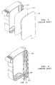
- a typical prior art print head includes a frame 10 having a flexible ink-impervious thin membrane 12 and a side cover 14 disposed on one side.
- a second membrane and a second side cover (not shown) are disposed on the opposite side of frame 10.
- the frame 10 is formed by a two-shot plastic injection molding process.
- a rigid outer frame 16 (Fig. 6) of high melt temperature plastic is formed in a first mold during a first injection molding step.
- the rigid outer frame 16 is then placed in a second mold and a low melt temperature rubber-like plastic is injected into the mold.
- the rubber-like plastic forms an inner frame 18 molded onto outer frame 16, the inner and outer frames forming the frame 10 as shown in Fig. 7.
- the inner frame 18 has oppositely facing flat side surfaces 20,20' which extend around the entire periphery of the inner frame 18.
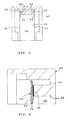
- the ink-impervious thin membranes 12 and 12' (Fig. 8) are heat staked to the surfaces 20 and 20' thereby forming a chamber or ink reservoir 22 bounded on opposite sides by the thin membranes and bounded around its periphery by the inner surface 24 of the inner frame 18.
- the outer frame 16 is molded to have a downwardly extending nose portion 16A (Fig. 6) having therein a standpipe 26 as shown in Fig. 6.
- the standpipe 26 has an ink flow channel 28 which extends through the standpipe and outer frame 16 to the bottom surface 30 of the nose.
- the inner frame 18 is molded around the standpipe 26 so that the opening into channel 28 is not closed as the inner frame 18 is molded onto outer frame 16. This permits ink to flow from reservoir 22 through the channel 28 to the bottom surface of the nose from whence it may be ejected through a nozzle plate (not shown).
- the prior art print head shown in Figs. 5-8 has a disadvantage in that the frame requires two separate and distinct molding steps thus making the frame 10 almost twice as expensive to manufacture as a similar frame formed in a single molding step.
- the device cannot be formed in a single molding step because different materials are required for the inner frame 18 and outer frame 16.
- the requirement that the impervious films 12, 12' be heat staked to the inner frame 16 dictates that the material used in forming the inner frame be a low melt temperature, rubber-like material. That is, the material comprising the inner frame must have a melt temperature less than that of the membrane material to prevent tear or damage to the membrane during the staking process and so that it melts to form a bond with the membranes 12,12' during the heat staking of the membranes. Since the inner frame material is somewhat flexible, the rigid outer frame must be made of a stiff material in order to support the flexible ink reservoir.
- print heads made by the two-shot molding process have a further disadvantage in that the ink reservoir may leak where the inner frame 18 is molded around the standpipe 24.
- a method of making a print head having an ink reservoir therein comprising:
- the adhesive material may be a hot melt adhesive such as ethylene vinyl acetate or a dry film adhesive pre-formed to the shapes of the bonding surfaces.
- a hot melt adhesive such as ethylene vinyl acetate or a dry film adhesive pre-formed to the shapes of the bonding surfaces.
- the flexible films may each comprise a laminated polymeric film and may include a surface ply of a higher melt temperature polymer such as polyethylene terephthalate to prevent sticking of the low melt temperature polymer to the heat sealing tool.
- a higher melt temperature polymer such as polyethylene terephthalate
- the flexible films may be polyethylene terephthalate and the adhesive bonding material may be a liquid epoxy.
- Figs. 1-4 illustrate a print head constructed according to the present invention.
- the print head includes a rigid frame 50, two flexible ink-impervious thin films 52,52' (Fig. 3) and two side covers 54, only one of the covers being shown in Fig 1.
- the rigid frame 50 is a monolithic structure formed by plastic injection molding in a single molding step so as to have the configuration shown in Fig. 2.
- Rigid frame 50 is molded with a large opening 56 extending through it from a first side 58 to a second side 59.
- the exterior surface 62 of the rigid frame 50 comprises the peripheral outer surface of the print head.
- the interior surface 64 of frame 50 comprises the peripheral wall of an ink reservoir 66 (Fig. 3) when the opening 56 is closed on both sides by thin films 52,52' as subsequently described.
- the frame 50 is molded so as to have a nose portion 50A and a standpipe (not visible), the standpipe having an ink flow channel extending from an inlet opening 60 on the interior of the frame to an opening (not visible) in the lower surface of the nose portion.
- the frame 50 is also molded so as to have two continuous support shelves or bonding surfaces 68,69 spaced from each other and surrounding the opening 56. The bonding surfaces 68,69 face in opposite directions with surface 68 facing toward the first side 58 of the frame and surface 69 facing toward the second side 59.
- an adhesive bonding material 70 (Figs. 3 and 4) is applied to the bonding surfaces 68,69.
- the flexible films 52, 52' are brought into position and adhesively secured to surfaces 68,69 by means of the adhesive bonding material 70.
- the thin flexible films 52,52' comprise a laminated low melt temperature polymeric material such as polyethylene and the adhesive bonding material is a hot melt adhesive.
- An ethylene vinyl acetate based hot melt similar to 3M Jet Melt 3764 is preferred.
- the thin flexible films 52,52' are secured to the bonding surfaces 68,69 by dispensing the hot melt adhesive onto the surfaces, bringing the thin films into contact with the adhesive, and heat sealing or staking the films.
- the heat sealing or staking is similar to the heat staking of the prior art described above except that the sealing temperature is such that the material of the frame 50 is not melted during the staking.
- the frame 50 comprises a high melt temperature material such as polyethylene terephthalate but obviously other plastic materials, with or without additives such as glass, may be used.
- the laminated flexible films may comprise a plurality of layers with a surface layer 72 comprising a higher melt temperature polymer such as polyethylene terephthalate or polyamid.
- a laminated flexible film 52 or 52' is placed in position for staking, the film is oriented so that the surface layer 72 faces the staking tool. Since the surface layer 72 has a higher melt temperature than the other layers, it does not melt and adhere to the heat sealing tool as the thin flexible films are bonded to the frame.
- the adhesive bonding material 70 may also take the form of a dry film adhesive pre-formed in shape to match the shape of the bonding surfaces 68,69.
- a suitable dry film adhesive for this purpose is 3M 556 ethylene vinyl acetate (EVA).
- EVA ethylene vinyl acetate
- the thin flexible films 52,52' are secured to bonding surfaces 68,69 by placing the dry film adhesive preforms against the bonding surfaces, placing the flexible films adjacent the preforms, and then applying pressure to press the films toward the frame while applying moderate heat.
- a double sided pressure sensitive tape such as 3M 4932 acrylic tape could also be used for this purpose.
- the thin flexible films 52,52' may be polyethylene terephthalate (Mylar) in which case a liquid epoxy may be used to secure the flexible films to the bonding surfaces 68,69.
- a liquid epoxy adhesives require post-curing which is a disadvantage in a high volume manufacturing operation.
- the present embodiment provides a method of making a print head which reduces the manufacturing cost by about 50% as compared to a print head produced by the prior art method described with respect to Figs. 5-8, the reduction in cost being attained by eliminating one of two molding steps. Since the frame, including the standpipe, is molded in one piece, the interface between two molded parts, and the attendant problem of ink leakage at the interface, are eliminated.
- the method of the present invention permits the making of print heads in the same configuration as print heads made by the method described with respect to Figs. 5-8.
- Fig. 8 it will be noted from Fig. 8 that the combined thickness of the inner and outer frames 16,18 of the prior art device is considerable.
- the frame 50 is cored according to general plastic design rules regarding wall thickness and the coring of thick sections so that the frame 50 exhibits a plurality of cavities 74 extending under a support shelf 32.
Landscapes
- Particle Formation And Scattering Control In Inkjet Printers (AREA)
- Ink Jet (AREA)
Applications Claiming Priority (2)
| Application Number | Priority Date | Filing Date | Title |
|---|---|---|---|
| US439912 | 1995-05-12 | ||
| US08/439,912 US6243117B1 (en) | 1995-05-12 | 1995-05-12 | Print head cartridge and method of making a print head cartridge by one-shot injection molding |
Publications (2)
| Publication Number | Publication Date |
|---|---|
| EP0742102A2 true EP0742102A2 (fr) | 1996-11-13 |
| EP0742102A3 EP0742102A3 (fr) | 1998-10-07 |
Family
ID=23746656
Family Applications (1)
| Application Number | Title | Priority Date | Filing Date |
|---|---|---|---|
| EP96301322A Withdrawn EP0742102A3 (fr) | 1995-05-12 | 1996-02-27 | Tête d'impression et son procédé de fabrication pour moulage par injection à étape-unique |
Country Status (5)
| Country | Link |
|---|---|
| US (2) | US6243117B1 (fr) |
| EP (1) | EP0742102A3 (fr) |
| JP (1) | JPH08300688A (fr) |
| KR (1) | KR100202785B1 (fr) |
| CA (1) | CA2169901A1 (fr) |
Cited By (13)
| Publication number | Priority date | Publication date | Assignee | Title |
|---|---|---|---|---|
| WO1998055316A1 (fr) * | 1997-06-06 | 1998-12-10 | Minnesota Mining And Manufacturing Company | Systeme de fixation dans une cartouche d'imprimante a jets d'encre et procede de fabrication |
| EP1348558A1 (fr) * | 2002-03-28 | 2003-10-01 | Brother Kogyo Kabushiki Kaisha | Cartouche d'encre et dispositif enregistreur |
| EP1348556A1 (fr) * | 2002-03-28 | 2003-10-01 | Brother Kogyo Kabushiki Kaisha | Cartouche d'encre |
| EP1348555A1 (fr) * | 2002-03-28 | 2003-10-01 | Brother Kogyo Kabushiki Kaisha | Cartouche d'encre |
| EP1348557A1 (fr) * | 2002-03-28 | 2003-10-01 | Brother Kogyo Kabushiki Kaisha | Cartouche d'encre et son procédé de fabrication |
| US6886928B2 (en) | 2002-03-28 | 2005-05-03 | Brother Kogyo Kabushiki Kaisha | Ink cartridge and method of production thereof |
| US6899418B2 (en) | 2002-03-28 | 2005-05-31 | Brother Kogyo Kabushiki Kaisha | Ink cartridge and recording device |
| US7137689B2 (en) | 2002-03-28 | 2006-11-21 | Brother Kogyo Kabushiki Kaisha | Ink cartridge |
| US7178911B2 (en) | 2001-03-30 | 2007-02-20 | Brother Kogyo Kabushiki Kaisha | Ink cartridge |
| US7226153B2 (en) | 2002-03-28 | 2007-06-05 | Brother Kogyo Kabushiki Kaisha | Ink cartridge |
| US7237884B2 (en) | 2001-03-30 | 2007-07-03 | Brother Kogyo Kabushiki Kaisha | Ink cartridge |
| US7380925B2 (en) | 2002-03-28 | 2008-06-03 | Brother Kogyo Kabushiki Kaisha | Ink cartridge |
| EP2108513A1 (fr) * | 1998-07-15 | 2009-10-14 | Seiko Epson Corporation | Unité d'alimentation d'encre |
Families Citing this family (33)
| Publication number | Priority date | Publication date | Assignee | Title |
|---|---|---|---|---|
| US6243117B1 (en) * | 1995-05-12 | 2001-06-05 | Lexmark International, Inc. | Print head cartridge and method of making a print head cartridge by one-shot injection molding |
| USD448797S1 (en) | 2000-07-14 | 2001-10-02 | Xerox Corporation | Ink tank |
| US6817707B1 (en) | 2003-06-18 | 2004-11-16 | Lexmark International, Inc. | Pressure controlled ink jet printhead assembly |
| US7159974B2 (en) * | 2003-10-06 | 2007-01-09 | Lexmark International, Inc. | Semipermeable membrane for an ink reservoir and method of attaching the same |
| US7156513B2 (en) * | 2004-07-08 | 2007-01-02 | Hewlett-Packard Development Company, L.P. | Ink cartridge component |
| US7828421B2 (en) * | 2005-09-29 | 2010-11-09 | Brother Kogyo Kabushiki Kaisha | Ink cartridge arrangements |
| US7591548B2 (en) * | 2005-09-29 | 2009-09-22 | Brother Kogyo Kabushiki Kaisha | Ink cartridge |
| US8025376B2 (en) * | 2005-09-29 | 2011-09-27 | Brother Kogyo Kabushiki Kaisha | Ink cartridges |
| US7575311B2 (en) * | 2005-09-29 | 2009-08-18 | Brother Kogyo Kabushiki Kaisha | Ink cartridge |
| US7578584B2 (en) * | 2005-09-29 | 2009-08-25 | Brother Kogyo Kabushiki Kaisha | Ink cartridge |
| US7635180B2 (en) * | 2005-09-29 | 2009-12-22 | Brother Kogyo Kabushiki Kaisha | Ink cartridge |
| US7669991B2 (en) * | 2005-09-29 | 2010-03-02 | Brother Kogyo Kabushiki Kaisha | Ink cartridge |
| KR100641658B1 (ko) * | 2005-10-25 | 2006-11-10 | 주식회사 잉크테크 | 프린터용 잉크 카트리지 |
| ATE552117T1 (de) * | 2005-10-25 | 2012-04-15 | Inktec Co Ltd | Tintenpatrone für drucker |
| KR100855544B1 (ko) * | 2006-03-18 | 2008-09-01 | 주식회사 잉크테크 | 프린터용 잉크 카트리지 및 잉크충전방법 |
| US7828424B2 (en) * | 2006-05-19 | 2010-11-09 | Xerox Corporation | Heater and drip plate for ink loader melt assembly |
| USD580971S1 (en) | 2006-09-08 | 2008-11-18 | Kenneth Yuen | Ink cartridge |
| US20080204528A1 (en) * | 2007-02-28 | 2008-08-28 | Kenneth Yuen | Ink cartridge |
| JP5145824B2 (ja) * | 2007-08-31 | 2013-02-20 | ブラザー工業株式会社 | インク容器 |
| USD599399S1 (en) | 2007-11-30 | 2009-09-01 | Brother Kogyo Kabushiki Kaisha | Ink cartridge |
| CA126185S (en) | 2007-11-30 | 2008-12-30 | Brother Ind Ltd | Ink cartridge |
| USD647134S1 (en) | 2007-11-30 | 2011-10-18 | Brother Industries, Ltd. | Ink cartridge |
| USD641400S1 (en) | 2007-11-30 | 2011-07-12 | Brother Industries, Ltd. | Ink cartridge |
| USD600278S1 (en) | 2007-11-30 | 2009-09-15 | Brother Kogyo Kabushiki Kaisha | Ink cartridge |
| US9457574B2 (en) | 2013-12-23 | 2016-10-04 | Palo Alto Research Center Incorporated | Process to fabricate an injection molded printhead with inkjet nozzle face plate |
| US9423188B2 (en) * | 2013-12-23 | 2016-08-23 | Palo Alto Research Center Incorporated | Molded plastic objects having an integrated heat spreader and methods of manufacture of same |
| US20150182688A1 (en) | 2013-12-31 | 2015-07-02 | Abbvie Inc. | Devices and methods for delivering a beneficial agent to a user |
| USD744586S1 (en) * | 2014-02-12 | 2015-12-01 | Samsung Electronics Co., Ltd. | Cartridge |
| USD746871S1 (en) | 2014-12-30 | 2016-01-05 | Abbvie Inc. | Interface portion of a pump |
| USD777831S1 (en) * | 2014-12-30 | 2017-01-31 | Abbvie Inc. | Cassette |
| USD777247S1 (en) * | 2014-12-30 | 2017-01-24 | Abbvie Inc. | Interface portion of a cassette |
| USD766424S1 (en) | 2014-12-30 | 2016-09-13 | Abbvie Inc. | Delivery device including pump and cassette |
| JP6590528B2 (ja) | 2015-05-25 | 2019-10-16 | キヤノン株式会社 | 液体供給部材の製造方法 |
Family Cites Families (13)
| Publication number | Priority date | Publication date | Assignee | Title |
|---|---|---|---|---|
| US3708798A (en) * | 1971-12-23 | 1973-01-02 | Ibm | Ink distribution for non-impact printing recorder |
| EP0244214B1 (fr) * | 1986-04-28 | 1991-07-10 | Hewlett-Packard Company | Tête d'impression à jet d'encre thermique |
| DE68920262T3 (de) * | 1988-10-14 | 2000-11-16 | Seiko Epson Corp., Tokio/Tokyo | Tintenkassette für einen Tintenstrahldrucker. |
| US5280300A (en) | 1991-08-27 | 1994-01-18 | Hewlett-Packard Company | Method and apparatus for replenishing an ink cartridge |
| US5359353A (en) * | 1991-06-19 | 1994-10-25 | Hewlett-Packard Company | Spring-bag printer ink cartridge with volume indicator |
| US5464578A (en) | 1992-03-18 | 1995-11-07 | Hewlett-Packard Company | Method of making a compact fluid coupler for thermal inkjet print cartridge ink reservoir |
| JP3110872B2 (ja) * | 1992-06-24 | 2000-11-20 | キヤノン株式会社 | インクジェット記録装置 |
| US5325119A (en) | 1992-08-12 | 1994-06-28 | Hewlett-Packard Company | Variable rate spring ink pressure regulator for a thermal ink jet printer |
| US5448818A (en) * | 1992-08-12 | 1995-09-12 | Hewlett-Packard Company | Method of assembly of a collapsible ink reservoir structure |
| CA2093981C (fr) | 1992-08-12 | 2001-03-20 | George T. Kaplinsky | Reservoir d'encre repliable et cartouche d'encre d'imprimante |
| EP0622235B1 (fr) * | 1993-04-30 | 1997-07-30 | Hewlett-Packard Company | Arrangement d'une couche de contact sur une cartouche d'impression en plastique |
| JPH07323570A (ja) * | 1994-05-31 | 1995-12-12 | Canon Inc | インクジェット記録ヘッド用インク供給系、及びインクタンク並びにこれらを具備するインクジェット記録装置 |
| US6243117B1 (en) * | 1995-05-12 | 2001-06-05 | Lexmark International, Inc. | Print head cartridge and method of making a print head cartridge by one-shot injection molding |
-
1995
- 1995-05-12 US US08/439,912 patent/US6243117B1/en not_active Expired - Lifetime
-
1996
- 1996-02-20 CA CA002169901A patent/CA2169901A1/fr not_active Abandoned
- 1996-02-27 KR KR1019960005514A patent/KR100202785B1/ko not_active Expired - Fee Related
- 1996-02-27 EP EP96301322A patent/EP0742102A3/fr not_active Withdrawn
- 1996-04-23 JP JP8126549A patent/JPH08300688A/ja active Pending
-
2000
- 2000-12-19 US US09/739,273 patent/US6283588B1/en not_active Expired - Lifetime
Cited By (18)
| Publication number | Priority date | Publication date | Assignee | Title |
|---|---|---|---|---|
| WO1998055316A1 (fr) * | 1997-06-06 | 1998-12-10 | Minnesota Mining And Manufacturing Company | Systeme de fixation dans une cartouche d'imprimante a jets d'encre et procede de fabrication |
| EP2108513A1 (fr) * | 1998-07-15 | 2009-10-14 | Seiko Epson Corporation | Unité d'alimentation d'encre |
| US7300144B2 (en) | 2001-03-30 | 2007-11-27 | Brother Kogyo Kabushiki Kaisha | Ink cartridge |
| US7237884B2 (en) | 2001-03-30 | 2007-07-03 | Brother Kogyo Kabushiki Kaisha | Ink cartridge |
| US7178911B2 (en) | 2001-03-30 | 2007-02-20 | Brother Kogyo Kabushiki Kaisha | Ink cartridge |
| US6976749B2 (en) | 2002-03-28 | 2005-12-20 | Brother Kogyo Kabushiki Kaisha | Ink cartridge and recording device |
| US6899418B2 (en) | 2002-03-28 | 2005-05-31 | Brother Kogyo Kabushiki Kaisha | Ink cartridge and recording device |
| US6938996B2 (en) | 2002-03-28 | 2005-09-06 | Brother Kogyo Kabushiki Kaisha | Ink cartridge and recording device |
| US6886928B2 (en) | 2002-03-28 | 2005-05-03 | Brother Kogyo Kabushiki Kaisha | Ink cartridge and method of production thereof |
| US7137689B2 (en) | 2002-03-28 | 2006-11-21 | Brother Kogyo Kabushiki Kaisha | Ink cartridge |
| US7152966B2 (en) | 2002-03-28 | 2006-12-26 | Brother Kogyo Kabushiki Kaisha | Ink cartridge and recording device |
| EP1348557A1 (fr) * | 2002-03-28 | 2003-10-01 | Brother Kogyo Kabushiki Kaisha | Cartouche d'encre et son procédé de fabrication |
| US7226153B2 (en) | 2002-03-28 | 2007-06-05 | Brother Kogyo Kabushiki Kaisha | Ink cartridge |
| EP1348555A1 (fr) * | 2002-03-28 | 2003-10-01 | Brother Kogyo Kabushiki Kaisha | Cartouche d'encre |
| US7284830B2 (en) | 2002-03-28 | 2007-10-23 | Brother Kogyo Kabushiki Kaisha | Ink cartridge and recording device |
| EP1348556A1 (fr) * | 2002-03-28 | 2003-10-01 | Brother Kogyo Kabushiki Kaisha | Cartouche d'encre |
| US7380925B2 (en) | 2002-03-28 | 2008-06-03 | Brother Kogyo Kabushiki Kaisha | Ink cartridge |
| EP1348558A1 (fr) * | 2002-03-28 | 2003-10-01 | Brother Kogyo Kabushiki Kaisha | Cartouche d'encre et dispositif enregistreur |
Also Published As
| Publication number | Publication date |
|---|---|
| US6283588B1 (en) | 2001-09-04 |
| CA2169901A1 (fr) | 1996-11-13 |
| JPH08300688A (ja) | 1996-11-19 |
| EP0742102A3 (fr) | 1998-10-07 |
| US6243117B1 (en) | 2001-06-05 |
| KR960040659A (ko) | 1996-12-17 |
| KR100202785B1 (ko) | 1999-06-15 |
Similar Documents
| Publication | Publication Date | Title |
|---|---|---|
| EP0742102A2 (fr) | Tête d'impression et son procédé de fabrication pour moulage par injection à étape-unique | |
| US5874971A (en) | Ink jet head connection unit, an ink jet cartridge, and an assembly method thereof | |
| EP0604235B1 (fr) | Film laminé pour réservoir d'encre | |
| US4434430A (en) | Ink jet printer head | |
| US5563643A (en) | Ink jet printhead and ink supply manifold assembly having ink passageway sealed therebetween | |
| MXPA03005654A (es) | Metodo para proteger tinta y proveer una adhesion mejorada durante el moldeo de laminas de lente lenticular en objetos plasticos. | |
| EP0657291B1 (fr) | Cartouche de jet d'encre | |
| JPH0958007A (ja) | インクタンク、該インクタンクの製造方法、前記インクタンクを用いるインクジェットカートリッジ及びインクジェット記録装置 | |
| US6767084B2 (en) | Ink-jet recording head and ink-jet recording apparatus | |
| EP0426406B1 (fr) | Carte pourvue d'un module à circuit intégré | |
| US5448818A (en) | Method of assembly of a collapsible ink reservoir structure | |
| EP1010532A3 (fr) | Imprimante et procédé de sa production | |
| JP3528985B2 (ja) | 液体インク供給カートリッジ及びその製造方法 | |
| EP0767062B1 (fr) | Procédé de liaison d'une plaque à buser sur une puce | |
| JPH10234621A (ja) | 暖房便座の製造方法 | |
| US6361146B1 (en) | Adhesive bonding laminates | |
| JP3671555B2 (ja) | インクタンク | |
| JP2000255082A (ja) | インクジェット記録用インクカートリッジの包装方法 | |
| JPS5812765A (ja) | インクジエツトヘツド | |
| JPH0577416A (ja) | インクジエツトヘツド | |
| JP2003053992A (ja) | 負圧を与える液体収納容器及び該容器を備えるインクジェット記録ヘッド | |
| JPH07314671A (ja) | インクジェット記録装置の記録ヘッド | |
| JPH02125738A (ja) | インクジェット記録ヘッド | |
| JPH10309811A (ja) | 記録ヘッドの保管方法、記録ヘッド用キャップ、インクジェットカートリッジの保管方法及び使用時取り扱い方法 | |
| JP2002120373A (ja) | 半導体機能部品、その製造方法、およびインクジェット記録ヘッド |
Legal Events
| Date | Code | Title | Description |
|---|---|---|---|
| PUAI | Public reference made under article 153(3) epc to a published international application that has entered the european phase |
Free format text: ORIGINAL CODE: 0009012 |
|
| AK | Designated contracting states |
Kind code of ref document: A2 Designated state(s): DE FR GB IT |
|
| PUAL | Search report despatched |
Free format text: ORIGINAL CODE: 0009013 |
|
| AK | Designated contracting states |
Kind code of ref document: A3 Designated state(s): DE FR GB IT |
|
| 17P | Request for examination filed |
Effective date: 19990204 |
|
| 17Q | First examination report despatched |
Effective date: 20000221 |
|
| STAA | Information on the status of an ep patent application or granted ep patent |
Free format text: STATUS: THE APPLICATION IS DEEMED TO BE WITHDRAWN |
|
| 18D | Application deemed to be withdrawn |
Effective date: 20000704 |