EP0426406B1 - Carte pourvue d'un module à circuit intégré - Google Patents
Carte pourvue d'un module à circuit intégré Download PDFInfo
- Publication number
- EP0426406B1 EP0426406B1 EP90311820A EP90311820A EP0426406B1 EP 0426406 B1 EP0426406 B1 EP 0426406B1 EP 90311820 A EP90311820 A EP 90311820A EP 90311820 A EP90311820 A EP 90311820A EP 0426406 B1 EP0426406 B1 EP 0426406B1
- Authority
- EP
- European Patent Office
- Prior art keywords
- card
- recess
- module
- opening
- circuit board
- Prior art date
- Legal status (The legal status is an assumption and is not a legal conclusion. Google has not performed a legal analysis and makes no representation as to the accuracy of the status listed.)
- Expired - Lifetime
Links
Images




Classifications
-
- G—PHYSICS
- G06—COMPUTING OR CALCULATING; COUNTING
- G06K—GRAPHICAL DATA READING; PRESENTATION OF DATA; RECORD CARRIERS; HANDLING RECORD CARRIERS
- G06K19/00—Record carriers for use with machines and with at least a part designed to carry digital markings
- G06K19/06—Record carriers for use with machines and with at least a part designed to carry digital markings characterised by the kind of the digital marking, e.g. shape, nature, code
- G06K19/067—Record carriers with conductive marks, printed circuits or semiconductor circuit elements, e.g. credit or identity cards also with resonating or responding marks without active components
- G06K19/07—Record carriers with conductive marks, printed circuits or semiconductor circuit elements, e.g. credit or identity cards also with resonating or responding marks without active components with integrated circuit chips
- G06K19/077—Constructional details, e.g. mounting of circuits in the carrier
- G06K19/0772—Physical layout of the record carrier
- G06K19/07728—Physical layout of the record carrier the record carrier comprising means for protection against impact or bending, e.g. protective shells or stress-absorbing layers around the integrated circuit
-
- G—PHYSICS
- G06—COMPUTING OR CALCULATING; COUNTING
- G06K—GRAPHICAL DATA READING; PRESENTATION OF DATA; RECORD CARRIERS; HANDLING RECORD CARRIERS
- G06K19/00—Record carriers for use with machines and with at least a part designed to carry digital markings
- G06K19/06—Record carriers for use with machines and with at least a part designed to carry digital markings characterised by the kind of the digital marking, e.g. shape, nature, code
- G06K19/067—Record carriers with conductive marks, printed circuits or semiconductor circuit elements, e.g. credit or identity cards also with resonating or responding marks without active components
- G06K19/07—Record carriers with conductive marks, printed circuits or semiconductor circuit elements, e.g. credit or identity cards also with resonating or responding marks without active components with integrated circuit chips
- G06K19/077—Constructional details, e.g. mounting of circuits in the carrier
- G06K19/07745—Mounting details of integrated circuit chips
-
- H—ELECTRICITY
- H10—SEMICONDUCTOR DEVICES; ELECTRIC SOLID-STATE DEVICES NOT OTHERWISE PROVIDED FOR
- H10W—GENERIC PACKAGES, INTERCONNECTIONS, CONNECTORS OR OTHER CONSTRUCTIONAL DETAILS OF DEVICES COVERED BY CLASS H10
- H10W90/00—Package configurations
- H10W90/701—Package configurations characterised by the relative positions of pads or connectors relative to package parts
- H10W90/751—Package configurations characterised by the relative positions of pads or connectors relative to package parts of bond wires
- H10W90/754—Package configurations characterised by the relative positions of pads or connectors relative to package parts of bond wires between a chip and a stacked insulating package substrate, interposer or RDL
Definitions
- the present invention relates to an IC (integrated circuit) card, and more particularly to structure for securing an IC module to a card base.
- the IC card has an IC chip having a CPU and memories. Since the recent IC card has a larger storage capacity than a conventional IC card, its use in place of a bankbook or a credit card is into consideration.
- the IC module including the IC chip is mounted in the IC card.
- the IC card there are various problems in the mounting of the IC module.
- Japanese Patent Application Laid-open 63-94646 and Japanese Utility Model Application Laid-open 61-46655 disclose IC module mounting structure.
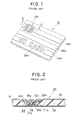
- Fig. 1 shows an external appearance of a conventional IC card
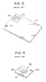
- Fig. 2 is a sectional view taken on a line II-II of Fig. 1 and shows the IC module mounting structure.
- the IC card 30 comprises a plastic card base 31, an IC module 32 embedded in the card base 31, and an overlay 36 on which various ornament patterns and characters 36a are printed.
- the IC module 32 has a plurality of contact patterns 32c which are exposed to the outside.
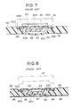
- a first recess 31 a and a second recess 31 b for housing the IC module 32 are formed in the card base 31 as shown in Fig. 3.
- the card base 31 is made by injection molding of ABS resin or by multi-layer laminating PVC (polyvinyl chloride) sheets.
- the IC module 32 is designed in such a way that an IC chip 33 is bonded to a circuit board 32a made of glass epoxy resin, and a seal portion 32b of sealing resin is formed on the circuit board 32a to seal the IC chip 33.
- the contact patterns 32c shown in Fig. 1 are formed on the back side of the circuit board 32a.
- the seal portion 32b of the IC module 32 is housed in the second recess 31 b of the card base 31, and the circuit board 32a is housed in the first recess 31a, while the outer periphery of the circuit board 32a is restricted by the peripheral wall of the first recess 31a, and the surfaces of the contact patterns are coplanar as the card base 31.
- Aliquid adhesive (not shown) is supplied into spaces among the circuit board 32a, the sealing portion 32b, the first recess 31a, and the second recess 31 b, and heated to be solidified.
- the IC module 32 is securely mounted on the card base 31.
- the IC card 30 has a small thickness as about 0.8 mm, and hence it must have an elasticity enough to allow to be bent to a certain extent so as not to be broken by an external force exerted thereon in use. Therefore, it is required that the card base 31 has an elasticity, while the seal portion 32b of the IC module 32 has a rigidity sufficient for protecting the IC module, and that the IC module 32 is firmly fixed to the card base 31.
- the material of the circuit board 32a and the seal portion 32b constituting the IC module 32 is different from that of the card base 31, it is difficult to obtain a liquid adhesive capable of reliably bonding them to each other.
- the adhesive strength in an adhesion state of the IC module changes with the adhered position thereof. Consequently, when the card base 31 is fixed, separation of an adhered portion between the card base 31 and the IC module 32 may occur. As a result, the IC module 32 may separate from the card base 31.
- the liquid adhesive When the liquid adhesive is heated, it can leak from a portion of the gap between the circuit board 32a and the first recess 31 a depending on the amount of the liquid adhesive and the bonding position. As a result, the surface of the overlay 36 on which pattern and characters 36a are printed may be contaminated. In addition, the card base 31 tends to deform because of the heat at the time when the liquid adhesive is heated.
- IC card structure in which the IC module can be secured to the card base without using the liquid adhesive.
- Such IC card structures are shown in Fig. 5 to Fig. 8.
- Fig. 5 to Fig. 8 the same reference numerals as those of Fig. 1 to Fig. 4 designate same parts as Figs. 1 to 4, and hence explanation thereof is omitted hereinafter.
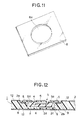
- the IC card structure shown in Fig. 5 is disclosed in U.S. Patent 4,792,843.
- an adhesive sheet 34 (called hot melting sheet) is fitted in the first recess 31 a and the second recess 31 b.
- the IC module 32 is put in the card base 31 so that the seal portion 32b of the IC module 32 and the circuit board 32a are located in the second recess 31 b and the first recess 31 a of the card base 31.
- the upper side of the IC module 32 is heated and downwardly pressed by a heat and pressure applying apparatus (not shown), so that the adhesive sheet 34 laid between the IC module 32 and the first and second recesses 31a and 31 b melts, and solidifies when it cools, thereby fixing the IC module 32 to the card base 31.
- the adhesive sheet is greatly improved in adhesive strength, and hence it is available for assembling IC module.
- the adhesive sheet 34 does not leak from the gap between the IC module 32 and the first and second recesses 31 a and 31b when heat and pressure are applied thereto.
- seal portion 32b sealing the IC chip 33 is required to be formed as thin as possible, a transfer molding method using a thermosetting resin is used for forming the seal portion.
- thermosetting resin is used for forming the seal portion.
- the recesses 31 a and 31 b of the card base 31 are formed when the card base 31 is formed by the injection molding process ofABS resin, or the recesses are formed by cutting the card base after the multi-layer laminating of PVC sheets.
- the ABS resin shrinks when it cools and solidifies, and thus the thickness of the bottom of the second recess 31 decreases and variations have been easily produced in the depth of the second recess 31 b.
- the recess can not be formed with accuracy, causing thickness variance of the bottom of the recess.
- the seal portion 32b of the IC module 32 may project from the second recess 31 b. If the swelled IC module is forcibly packed in the second recess 31 b, the underside of the card base 31 (the opposite surface to the second surface 31 b) swells, thus, deteriorating the external appearance of the IC card.
- U.S. Patent 4,552,383 discloses an IC card which may solve the above described problems.
- Fig. 7 and Fig. 8 show the IC card.
- a reference numeral 40 designates a card base which is provided with a first recess 40a and a second recess 40b.
- An IC module 42 comprises a circuit board 43 having contact patterns 43a on the upper surface thereof, an IC chip 44 mounted on the circuit board 43, and a sealing portion 45 for sealing the IC chip.
- the IC chip 44 and contact patterns 43a are connected to each other by bonding wires and through hole patterns 43b.
- An adhesive sheet 46 is provided only between a peripheral portion of the circuit board 43 and a bottom of the first recess 40a.
- a heat and pressure applying apparatus 41 is set on the upper surface of the circuit board 43 of the IC module 42 to heat and press the IC module.
- the adhesive sheet 46 is melted so that only the peripheral portion of the circuit board 43 is fixed to the bottom of the first recess 40a.
- the peripheral sides of the circuit board 43 engage with the inner wall of the first recess 40a, thereby positioning the IC module 42.
- the second recess 40b has sufficient depth and a capacity to allow shape variation of the seal portion 45 of the IC module 42.
- the IC module 42 is mounted in the first and second recesses 40a and 40b with a space 49 between the seal portion 45 and the bottom of the second recess 40b. However, according to circumstances, the underside of the seal portion 45 may contact with the bottom of the second recess 40b.
- the seal portion 45 has not high accuracy in dimension, it is kept free from the second recess 40b by providing the gap therebetween. Furthermore, only the periphery portion of the circuit board 43 which has high accuracy is fixed to the first recess 40a through the adhesive sheet 46. Consequently, the swelling of the IC module is prevented.
- the IC module is firmly fixed to the card base, but it is also important that the surface of the card base 31 is kept smooth and flat until the overlay or the printing and a hard coat are performed thereon.
- the IC card structure has a defect that a depression is formed in the thin portion 40c of the card base 40 as shown in Fig. 8. This is caused for the following reason.
- the IC module 42 is mounted on the card base 40 with only the periphery portion of the circuit board 43, fixed on the first recess 40a through the adhesive sheet 46.
- the heat and pressure applying apparatus 41 set on the circuit board 43 heats the adhesive sheet 46, the heat is transmitted not only to the adhesive sheet 46 but also to the card base 40, thereby heating the air in the space 49 between the seal portion 45 and the second recess 40b. While being heated, the air in the space 49 is expanded. Therefore, the thin portion 40c projects outwardly and a apart of the air discharges from the space 49.
- the temperature of the air in the space 49 falls to a normal temperature, so that the volume of the air decreases and the pressure in the space is decompressed.
- the pressure of the air in the space becomes lower than the atmospheric pressure, so that the thin portion 40c is pushed into the space to produce a depression 47 as shown in Figure 8.
- the depression 47 causes incomplete adhesion between the hard coat and the card base, and hence the printing on the hard coat may be bad at the depression.
- the object of the present invention is to provide an IC card in which the IC module is fixed to the card base by a thermo reactive adhesive without forming a depression on the card base.
- an IC card comprising:
- the opening is formed in the card base.
- the opening is a through hole formed in the circuit board for connecting the contact pattern with the IC chip.
- an IC card 1 comprises a card base 2 having a first recess 2a, a second recess 2b, an IC module 3, and an adhesive sheet 8.
- the second recess 2b has a circular shape in plan view and is positioned at a central portion of the first recess 2a as shown in Fig. 9.
- Athin portion 2c defining the bottom of the second recess 2b has an opening 2d.
- the adhesive sheet 8 has an opening 8a for receiving the IC module 3.
- the IC module 3 comprises a circuit board 4 having a contact patterns 5 formed on the upper surface thereof, an IC chip 6 mounted on the underside of the circuit board 4, and a seal portion 7 which seals the IC chip 6 by the transfer molding method using a thermosetting resin.
- the IC chip 6 and contact patterns 5 are connected by bonding wires and through hole electrodes 5a.
- the adhesive sheet 8 is put in the first recess 2a and the circuit board 4 of the IC module is put on the adhesive sheet.
- the outer peripheral sides of the circuit board 4 are restricted by inner walls of the first recess 2a, and only the underside of the peripheral portion of the circuit board 2a is fixed to the first recess 2a through the adhesive sheet 8.
- the seal portion 7 of the IC module 3 is housed in the second recess 2b.
- the air in the space 9 expands with the heating of the IC module 3, a part of the air discharges from the space 9 passing through the opening 2d, and hence the pressure difference between the space 9 and the atmosphere does not occur.
- the thin portion 2c is not depressed when cooled, because the space 9 is not decompressed through the opening 2d.
- the opening 2d is filled with a seal member 11 such as an adhesive as shown in Fig. 10.
- an overlay or a hard coat is adhered on the card base 2 to cover the seal member 11.
- seal member 11 may be omitted as shown in Fig. 12, because the opening 2d of the card base 2 is perfectly closed by an overlay 12.
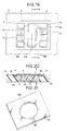
- the circuit board 4 has an opening 4a at such a position that the space 9 and the atmosphere are communicated with each other through the opening 4a.
- the opening is formed at the time when through hole electrodes 5a are formed in the contact patterns 5.
- an indentation 2e is formed in the inner wall of the second recess 2b to widen the space, and the opening 4a is formed to communicate with the widened space as shown in Fig. 14.
- the IC card is characterized in that the space 9 in the second recess 2b communicates with the atmosphere through the through hole electrodes 5a. More particularly, a pair of through hole electrodes 5a which are positioned symmetrically about the center of the second recess 2b are selected, each of which communicates with the space 9 through a groove 2f formed in the bottom of the first recess 2a. A pair of slits 8c are further provided in the adhesive sheet 8 so as to communicate the groove 2f with the through hole electrode 5a.
- Figs. 17 and 18 show the fourth embodiment of the present invention.
- An opening 10 is formed in the card base 2, and the groove 2f is formed in the first recess 2a so as to communicate the space 9 with the opening 10.
- the adhesive sheet 8 a notch is previously formed for communicating the opening 10 with groove 2f.
- the overlay orthe printing and the hard coat are not shown in the drawings, it is applied to the card base 2 so as to hide the opening 10.
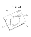
- the adhesive sheet 8 has a slit 8b communicating with the opening 8a for the IC module 3, and an opening 10 constituted by a notch 2g is formed in the card base 2 so as to be communicated with the slit 8b.
- the space 9 communicates with the atmosphere through the slit 8b and the opening 10.
- the IC module is mounted in the card base in such a way that the seal portion of the IC module is positioned in the second recess of the card base with a space between the card base and IC module, and the circuit board of the 10 module is fixed to the first recess of the card base with the thermo reactive adhesive sheet, and the IC card is provided with an opening for discharging the air from the space.
- the opening can be formed at a desired position in the card base and the circuit board of the IC module.
Landscapes
- Engineering & Computer Science (AREA)
- Computer Hardware Design (AREA)
- Microelectronics & Electronic Packaging (AREA)
- Physics & Mathematics (AREA)
- General Physics & Mathematics (AREA)
- Theoretical Computer Science (AREA)
- Credit Cards Or The Like (AREA)
Claims (13)
caractérisée en ce qu'un trou (2d;4a;2f,5a;10) est prévu entre ledit espace (9) et la surface extérieure de la dite carte CI.
Applications Claiming Priority (2)
| Application Number | Priority Date | Filing Date | Title |
|---|---|---|---|
| JP281907/89 | 1989-10-31 | ||
| JP28190789 | 1989-10-31 |
Publications (4)
| Publication Number | Publication Date |
|---|---|
| EP0426406A2 EP0426406A2 (fr) | 1991-05-08 |
| EP0426406A3 EP0426406A3 (en) | 1993-03-24 |
| EP0426406B1 true EP0426406B1 (fr) | 1995-05-10 |
| EP0426406B2 EP0426406B2 (fr) | 1998-08-19 |
Family
ID=17645621
Family Applications (1)
| Application Number | Title | Priority Date | Filing Date |
|---|---|---|---|
| EP90311820A Expired - Lifetime EP0426406B2 (fr) | 1989-10-31 | 1990-10-29 | Carte pourvue d'un module à circuit intégré |
Country Status (6)
| Country | Link |
|---|---|
| EP (1) | EP0426406B2 (fr) |
| JP (1) | JP3095766B2 (fr) |
| AT (1) | ATE122485T1 (fr) |
| CA (1) | CA2027823C (fr) |
| DE (1) | DE69019298T3 (fr) |
| ES (1) | ES2074139T5 (fr) |
Families Citing this family (19)
| Publication number | Priority date | Publication date | Assignee | Title |
|---|---|---|---|---|
| JPH07182471A (ja) * | 1991-01-10 | 1995-07-21 | Nec Corp | Icカード |
| FR2684471B1 (fr) * | 1991-12-02 | 1994-03-04 | Solaic | Procede de fabrication d'une carte a memoire et carte a memoire ainsi obtenue. |
| DE4209184C1 (fr) * | 1992-03-21 | 1993-05-19 | Orga Kartensysteme Gmbh, 6072 Dreieich, De | |
| JPH06166286A (ja) * | 1992-11-30 | 1994-06-14 | Sony Corp | メモリカードの加熱圧着方法及び圧着機 |
| US5956601A (en) * | 1996-04-25 | 1999-09-21 | Kabushiki Kaisha Toshiba | Method of mounting a plurality of semiconductor devices in corresponding supporters |
| DE29709618U1 (de) * | 1997-06-03 | 1997-08-07 | Sternberg, Dirk, 94568 St Oswald | Chipkarte und Kartenadapter |
| FR2794552B1 (fr) * | 1999-06-03 | 2001-08-31 | Gemplus Card Int | Procede de collage a chaud d'un module electronique dans une carte a puce |
| GB2352999A (en) * | 1999-07-21 | 2001-02-14 | Allan Walter Sills | Smart card with chip carrier with contact pads fitted into aperture of card base |
| EP2418608A1 (fr) * | 2010-07-23 | 2012-02-15 | Gemalto SA | Module électronique sécurisé, dispositif à module électronique sécurisé et procédé de fabrication |
| EP3168787A1 (fr) | 2015-11-11 | 2017-05-17 | Mastercard International Incorporated | Carte de circuit intégré |
| EP3168788A1 (fr) | 2015-11-11 | 2017-05-17 | Mastercard International Incorporated | Carte de circuit intégré |
| PL3491584T3 (pl) * | 2016-07-27 | 2022-11-07 | Composecure Llc | Elektroniczne komponenty do kart transakcyjnych i sposoby ich wytwarzania |
| US10762412B2 (en) | 2018-01-30 | 2020-09-01 | Composecure, Llc | DI capacitive embedded metal card |
| US10977540B2 (en) | 2016-07-27 | 2021-04-13 | Composecure, Llc | RFID device |
| US11618191B2 (en) | 2016-07-27 | 2023-04-04 | Composecure, Llc | DI metal transaction devices and processes for the manufacture thereof |
| US11151437B2 (en) | 2017-09-07 | 2021-10-19 | Composecure, Llc | Metal, ceramic, or ceramic-coated transaction card with window or window pattern and optional backlighting |
| PE20250343A1 (es) | 2017-09-07 | 2025-02-06 | Composecure Llc | Tarjeta de transaccion con componentes electronicos incorporados y procedimiento para su fabricacion |
| EP4109337B1 (fr) | 2017-10-18 | 2024-08-28 | Composecure LLC | Carte de transaction metallique, céramique ou avec rêvetement céramique avec fenêtre ou motif de fênetre e avec rétroéclairage |
| JP7485005B1 (ja) * | 2022-12-19 | 2024-05-16 | 株式会社レゾナック | 接合体の製造方法、接合体、及び電気電子部品 |
Family Cites Families (2)
| Publication number | Priority date | Publication date | Assignee | Title |
|---|---|---|---|---|
| DE3151408C1 (de) * | 1981-12-24 | 1983-06-01 | GAO Gesellschaft für Automation und Organisation mbH, 8000 München | Ausweiskarte mit einem IC-Baustein |
| DE3338597A1 (de) * | 1983-10-24 | 1985-05-02 | GAO Gesellschaft für Automation und Organisation mbH, 8000 München | Datentraeger mit integriertem schaltkreis und verfahren zur herstellung desselben |
-
1990
- 1990-10-17 CA CA002027823A patent/CA2027823C/fr not_active Expired - Fee Related
- 1990-10-23 JP JP02283422A patent/JP3095766B2/ja not_active Expired - Fee Related
- 1990-10-29 AT AT90311820T patent/ATE122485T1/de active
- 1990-10-29 EP EP90311820A patent/EP0426406B2/fr not_active Expired - Lifetime
- 1990-10-29 ES ES90311820T patent/ES2074139T5/es not_active Expired - Lifetime
- 1990-10-29 DE DE69019298T patent/DE69019298T3/de not_active Expired - Fee Related
Also Published As
| Publication number | Publication date |
|---|---|
| ES2074139T3 (es) | 1995-09-01 |
| EP0426406A3 (en) | 1993-03-24 |
| CA2027823C (fr) | 1994-11-08 |
| ATE122485T1 (de) | 1995-05-15 |
| DE69019298D1 (de) | 1995-06-14 |
| JP3095766B2 (ja) | 2000-10-10 |
| EP0426406B2 (fr) | 1998-08-19 |
| DE69019298T3 (de) | 1999-04-15 |
| JPH03205197A (ja) | 1991-09-06 |
| CA2027823A1 (fr) | 1991-05-01 |
| ES2074139T5 (es) | 1999-01-01 |
| DE69019298T2 (de) | 1996-01-04 |
| EP0426406A2 (fr) | 1991-05-08 |
Similar Documents
| Publication | Publication Date | Title |
|---|---|---|
| EP0426406B2 (fr) | Carte pourvue d'un module à circuit intégré | |
| US4994659A (en) | IC card | |
| US5026452A (en) | Method of producing IC cards | |
| US5346576A (en) | Method of manufacturing IC card | |
| US5272374A (en) | Production method for an IC card and its IC card | |
| JP2849594B2 (ja) | 電子モジュールの封止方法 | |
| JPH0130149B2 (fr) | ||
| US4417413A (en) | Identification card with IC chip and a method for manufacturing the same | |
| JP2812485B2 (ja) | メモリカードの製造方法 | |
| US4463971A (en) | Identification card having an IC module | |
| AU726884B2 (en) | Method of making smart cards | |
| US4904429A (en) | Method of producing a molding of foamed resin having a section for fitting an electrical part | |
| US5935497A (en) | Method of printing a graphic on a memory card | |
| US5514240A (en) | Method for incorporating a carrier element | |
| US7320738B2 (en) | Method for encapsulation of a chip card and module obtained thus | |
| WO2002028613A1 (fr) | Appareil et procede de moulage | |
| JP2001084347A (ja) | カード型記憶装置及びその製造方法 | |
| JPH0417343A (ja) | 薄型半導体装置の製造方法 | |
| JPH02301155A (ja) | Icモジュールの固定方法 | |
| US5877544A (en) | Electronic micropackage for an electronic memory card | |
| JPH03114788A (ja) | Icカード構造 | |
| KR0129760B1 (ko) | 보호막을 가진 기판과 그것을 사용한 광메모리 장치 제조방법 | |
| JPH09183284A (ja) | 非接触型icカード及びその製造方法 | |
| JP3126782B2 (ja) | 薄型半導体装置の製造方法 | |
| JPH0262398B2 (fr) |
Legal Events
| Date | Code | Title | Description |
|---|---|---|---|
| PUAI | Public reference made under article 153(3) epc to a published international application that has entered the european phase |
Free format text: ORIGINAL CODE: 0009012 |
|
| AK | Designated contracting states |
Kind code of ref document: A2 Designated state(s): AT BE CH DE ES FR GB IT LI LU NL SE |
|
| PUAL | Search report despatched |
Free format text: ORIGINAL CODE: 0009013 |
|
| AK | Designated contracting states |
Kind code of ref document: A3 Designated state(s): AT BE CH DE ES FR GB IT LI LU NL SE |
|
| 17P | Request for examination filed |
Effective date: 19930621 |
|
| 17Q | First examination report despatched |
Effective date: 19931119 |
|
| GRAA | (expected) grant |
Free format text: ORIGINAL CODE: 0009210 |
|
| AK | Designated contracting states |
Kind code of ref document: B1 Designated state(s): AT BE CH DE ES FR GB IT LI LU NL SE |
|
| REF | Corresponds to: |
Ref document number: 122485 Country of ref document: AT Date of ref document: 19950515 Kind code of ref document: T |
|
| REF | Corresponds to: |
Ref document number: 69019298 Country of ref document: DE Date of ref document: 19950614 |
|
| ITF | It: translation for a ep patent filed | ||
| ET | Fr: translation filed | ||
| REG | Reference to a national code |
Ref country code: ES Ref legal event code: FG2A Ref document number: 2074139 Country of ref document: ES Kind code of ref document: T3 |
|
| PLBI | Opposition filed |
Free format text: ORIGINAL CODE: 0009260 |
|
| PLAB | Opposition data, opponent's data or that of the opponent's representative modified |
Free format text: ORIGINAL CODE: 0009299OPPO |
|
| PLBQ | Unpublished change to opponent data |
Free format text: ORIGINAL CODE: EPIDOS OPPO |
|
| PLBF | Reply of patent proprietor to notice(s) of opposition |
Free format text: ORIGINAL CODE: EPIDOS OBSO |
|
| 26 | Opposition filed |
Opponent name: GIESECKE & DEVRIENT GMBH Effective date: 19960209 |
|
| R26 | Opposition filed (corrected) |
Opponent name: GIESECKE & DEVRIENT GMBH Effective date: 19960209 |
|
| NLR1 | Nl: opposition has been filed with the epo |
Opponent name: GIESECKE & DEVRIENT GMBH |
|
| PLBF | Reply of patent proprietor to notice(s) of opposition |
Free format text: ORIGINAL CODE: EPIDOS OBSO |
|
| PLAW | Interlocutory decision in opposition |
Free format text: ORIGINAL CODE: EPIDOS IDOP |
|
| PLAW | Interlocutory decision in opposition |
Free format text: ORIGINAL CODE: EPIDOS IDOP |
|
| ITF | It: translation for a ep patent filed | ||
| PLAW | Interlocutory decision in opposition |
Free format text: ORIGINAL CODE: EPIDOS IDOP |
|
| PUAH | Patent maintained in amended form |
Free format text: ORIGINAL CODE: 0009272 |
|
| STAA | Information on the status of an ep patent application or granted ep patent |
Free format text: STATUS: PATENT MAINTAINED AS AMENDED |
|
| 27A | Patent maintained in amended form |
Effective date: 19980819 |
|
| AK | Designated contracting states |
Kind code of ref document: B2 Designated state(s): AT BE CH DE ES FR GB IT LI LU NL SE |
|
| REG | Reference to a national code |
Ref country code: CH Ref legal event code: AEN Free format text: MAINTIEN DU BREVET DONT L'ETENDUE A ETE MODIFIEE |
|
| NLR2 | Nl: decision of opposition | ||
| NLR3 | Nl: receipt of modified translations in the netherlands language after an opposition procedure | ||
| PGFP | Annual fee paid to national office [announced via postgrant information from national office to epo] |
Ref country code: ES Payment date: 19981019 Year of fee payment: 9 |
|
| ET3 | Fr: translation filed ** decision concerning opposition | ||
| REG | Reference to a national code |
Ref country code: ES Ref legal event code: DC2A Kind code of ref document: T5 Effective date: 19981118 |
|
| PGFP | Annual fee paid to national office [announced via postgrant information from national office to epo] |
Ref country code: SE Payment date: 19991007 Year of fee payment: 10 |
|
| PGFP | Annual fee paid to national office [announced via postgrant information from national office to epo] |
Ref country code: FR Payment date: 19991011 Year of fee payment: 10 |
|
| PGFP | Annual fee paid to national office [announced via postgrant information from national office to epo] |
Ref country code: AT Payment date: 19991013 Year of fee payment: 10 |
|
| PGFP | Annual fee paid to national office [announced via postgrant information from national office to epo] |
Ref country code: LU Payment date: 19991022 Year of fee payment: 10 |
|
| PGFP | Annual fee paid to national office [announced via postgrant information from national office to epo] |
Ref country code: GB Payment date: 19991027 Year of fee payment: 10 Ref country code: CH Payment date: 19991027 Year of fee payment: 10 |
|
| PGFP | Annual fee paid to national office [announced via postgrant information from national office to epo] |
Ref country code: NL Payment date: 19991029 Year of fee payment: 10 |
|
| PGFP | Annual fee paid to national office [announced via postgrant information from national office to epo] |
Ref country code: DE Payment date: 19991102 Year of fee payment: 10 |
|
| PGFP | Annual fee paid to national office [announced via postgrant information from national office to epo] |
Ref country code: BE Payment date: 19991221 Year of fee payment: 10 |
|
| PG25 | Lapsed in a contracting state [announced via postgrant information from national office to epo] |
Ref country code: LU Free format text: LAPSE BECAUSE OF NON-PAYMENT OF DUE FEES Effective date: 20001029 Ref country code: GB Free format text: LAPSE BECAUSE OF NON-PAYMENT OF DUE FEES Effective date: 20001029 Ref country code: AT Free format text: LAPSE BECAUSE OF NON-PAYMENT OF DUE FEES Effective date: 20001029 |
|
| PG25 | Lapsed in a contracting state [announced via postgrant information from national office to epo] |
Ref country code: SE Free format text: THE PATENT HAS BEEN ANNULLED BY A DECISION OF A NATIONAL AUTHORITY Effective date: 20001030 Ref country code: ES Free format text: LAPSE BECAUSE OF NON-PAYMENT OF DUE FEES Effective date: 20001030 |
|
| PG25 | Lapsed in a contracting state [announced via postgrant information from national office to epo] |
Ref country code: LI Free format text: LAPSE BECAUSE OF NON-PAYMENT OF DUE FEES Effective date: 20001031 Ref country code: CH Free format text: LAPSE BECAUSE OF NON-PAYMENT OF DUE FEES Effective date: 20001031 Ref country code: BE Free format text: LAPSE BECAUSE OF NON-PAYMENT OF DUE FEES Effective date: 20001031 |
|
| BERE | Be: lapsed |
Owner name: CITIZEN WATCH CO. LTD Effective date: 20001031 |
|
| PG25 | Lapsed in a contracting state [announced via postgrant information from national office to epo] |
Ref country code: NL Free format text: LAPSE BECAUSE OF NON-PAYMENT OF DUE FEES Effective date: 20010501 |
|
| REG | Reference to a national code |
Ref country code: CH Ref legal event code: PL |
|
| EUG | Se: european patent has lapsed |
Ref document number: 90311820.6 |
|
| GBPC | Gb: european patent ceased through non-payment of renewal fee |
Effective date: 20001029 |
|
| PG25 | Lapsed in a contracting state [announced via postgrant information from national office to epo] |
Ref country code: FR Free format text: LAPSE BECAUSE OF NON-PAYMENT OF DUE FEES Effective date: 20010629 |
|
| NLV4 | Nl: lapsed or anulled due to non-payment of the annual fee |
Effective date: 20010501 |
|
| PG25 | Lapsed in a contracting state [announced via postgrant information from national office to epo] |
Ref country code: DE Free format text: LAPSE BECAUSE OF NON-PAYMENT OF DUE FEES Effective date: 20010703 |
|
| REG | Reference to a national code |
Ref country code: FR Ref legal event code: ST |
|
| REG | Reference to a national code |
Ref country code: ES Ref legal event code: FD2A Effective date: 20011113 |
|
| PG25 | Lapsed in a contracting state [announced via postgrant information from national office to epo] |
Ref country code: IT Free format text: LAPSE BECAUSE OF NON-PAYMENT OF DUE FEES;WARNING: LAPSES OF ITALIAN PATENTS WITH EFFECTIVE DATE BEFORE 2007 MAY HAVE OCCURRED AT ANY TIME BEFORE 2007. THE CORRECT EFFECTIVE DATE MAY BE DIFFERENT FROM THE ONE RECORDED. Effective date: 20051029 |