EP0742664A2 - Méthode pour parler à main levée pour un système de transmission à canaux multiples - Google Patents
Méthode pour parler à main levée pour un système de transmission à canaux multiples Download PDFInfo
- Publication number
- EP0742664A2 EP0742664A2 EP96106492A EP96106492A EP0742664A2 EP 0742664 A2 EP0742664 A2 EP 0742664A2 EP 96106492 A EP96106492 A EP 96106492A EP 96106492 A EP96106492 A EP 96106492A EP 0742664 A2 EP0742664 A2 EP 0742664A2
- Authority
- EP
- European Patent Office
- Prior art keywords
- dlm
- short
- term mean
- coupling
- xsam
- Prior art date
- Legal status (The legal status is an assumption and is not a legal conclusion. Google has not performed a legal analysis and makes no representation as to the accuracy of the status listed.)
- Granted
Links
Images


Classifications
-
- H—ELECTRICITY
- H04—ELECTRIC COMMUNICATION TECHNIQUE
- H04M—TELEPHONIC COMMUNICATION
- H04M9/00—Arrangements for interconnection not involving centralised switching
- H04M9/08—Two-way loud-speaking telephone systems with means for conditioning the signal, e.g. for suppressing echoes for one or both directions of traffic
Definitions
- the invention relates to a hands-free method for a multi-channel transmission system, namely for stereophonic hands-free speaking for the transmission of the spatial acoustics and for multi-channel hands-free speaking for the reproduction of different speaker locations at a conference table or for conferences in which a large number of participants are interconnected from several locally separated rooms.
- a single-channel transmission system for example in a hands-free system for telephones, a large number of problems have already been dealt with which result from the coupling between the loudspeaker and the microphone, from the influence of the ambient noise and from the mastery of the intercom situation.
- a circuit arrangement for dynamically controlling a terminal in which the degree of amplification of the signal voltages supplied by a microphone is adapted to the voltage value of these signal voltages using a controllable dynamic compander, cf. DE 37 24 346 A1. It is thereby achieved that in the case of several persons using the hands-free facility of a subscriber, these act on the opposite side for the subscriber as if they were at the same distance from the end device and as if they were speaking at the same volume, while noise sources have hardly any influence on the transmission and the annoying reverberation is avoided.
- a further improvement in the hands-free quality is achieved if a controlled echo canceller is connected upstream of the compander or a voice-controlled scale is connected downstream, cf. DE 43 05 256 A1.
- the publication describes that when using four adaptive filters, there is no clear, optimal solution for setting the filter coefficients for the compensation of the echoes resulting from the four possible couplings.
- the specified solution with two digital filters is based on the fact that, depending on the input signal of the right and left loudspeakers, a switch is made to a digital filter and the impulse response on the right microphone is evaluated by the right and left loudspeakers.
- the calculation of the filter coefficients is only correct if a microphone receives signals from only one loudspeaker.
- the evaluation of sum or difference signals as described here harbors the risk of incorrect measurements and can result in system instability.
- the use of digital filters in multichannel transmission systems is very complex since, for example, nine filters have to be calculated for a three-channel system. For example, the required working speed of a computer with a sampling rate of 24 kHz and a filter length of 1000 coefficients, corresponding to a time window of 41 ms, is 864 million instructions per second.
- a multichannel transmission system is also known, in which a digital filter is used for each speaker and microphone, cf. EP 627 825 A2.
- the channel for calculating the filter coefficients is selected via a detector circuit, in which the signal with the greatest power appears on the loudspeaker. In order to limit the effort, this solution makes a compromise between the number of adaptive filters and the quality gain through echo cancellation.
- the invention provides an inexpensive hands-free method for a multi-channel system.
- the essence of the invention is that from the multitude of possible coupling factors between loudspeakers and microphones, the respective greatest current coupling factor is always used for setting the transfer function of a compander due to certain decision conditions. Since the individual coupling factors are available separately, an optimal setting of the microphone sensitivity in the intercom and reception mode is possible. Due to the noise suppression on each microphone, systems with large numbers of participants can be implemented without affecting the signal-to-noise ratio. The reverberation caused by the acoustic coupling of the speaker to neighboring microphones is weakened.
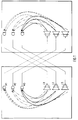
- FIG. 1 shows a three-channel transmission system between a first room and a second room, three microphones M1, M2, M3 and three loudspeakers L1, L2, L3 being located in the first room , between which there are a total of nine couplings.
- An essential task, which is solved by the method according to the invention, is to determine the couplings in such a way that the stability of the system is guaranteed and a natural conversation between the participants in the first room and those in the second room is made possible.
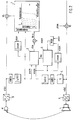
- FIG. 2 shows a transmission branch with a microphone M, a reception branch with a loudspeaker L, a circuit arrangement for determining the coupling factor dlm with a coupling estimator 2 and a control device 3, and a compander 1, the transmission characteristic of which is shown in FIG Depending on the acoustic environmental conditions can be shifted briefly and thus affects the transmission gain VS.
- the current coupling factor dlm can be calculated from the ratio of the short-term mean.
- the short-term mean value of the sample value of the transmission signal ysam is composed of the sum of the levels of the local signal and the return signal coming from the loudspeaker L to the microphone M.
- a useful measurement of the coupling factor is only possible, however, if the local speaker does not speak and suitable signals are received from the remote subscriber. Therefore, the coupling estimator 2 is controlled by the control device 3.
- a delay line 4 bridges the time taken for the received signal x (k) from a D / A converter 5 to travel from the loudspeaker L to the microphone M and an A. / D converter 6 required.
- the delay time ⁇ must be dimensioned such that the return signal is applied to the coupling estimator 2 earlier or simultaneously with the delayed reception signal.
- the control device 3 defines the conditions under which the quotient described with equation (1) may be evaluated.
- the long-term mean value of the received signal xlam is formed from the short-term mean value of the sample value of the received signal xsam.
- a minimum value detector as shown in FIG. 4 as module 5.13, can also be used. With such a minimum value detector, the smallest short-term mean value of the sample value of the received signal min (xsam) is recognized and held for a time interval of, for example, 5 s. This results in the possibility of distinguishing speech, which is generally characterized by high dynamics, from a generally more uniform ambient noise.
- the coupling factor dlm is weighted with the short-term mean value of the received signal xsam and the resulting signal thrs determines the short-term shift in the transmission characteristic of the compander 1.
- the transmission characteristic of the compander 1 With a fixed coupling between loudspeaker L and microphone M, i. H. large coupling factor dlm, the transmission characteristic of the compander 1 is briefly shifted to the right so that the echo signals arriving in the microphone M are not amplified and thus suppressed.
- the transmission characteristic curve of the compander 1 is set as a function of the current ambient noise and the gain VE in the reception branch is determined by the long-term mean value of the transmit signal ylam obtained by integration from the short-term mean value of the transmit signal ysam.
- the transmission characteristic of compander 1 is shifted to the right, so that the transmission gain VS is set such that the ambient noise level must be exceeded in order to send a signal to the receiver.
- the coupling estimator 2 in FIG. 2 will now be described in more detail below with the aid of FIG. 3 and FIG. 4.
- a distinction between the short-term mean value of the received signal xsam and the delayed short-term mean value of the received signal xsamd has been omitted; this distinction is taken into account in FIG. 4.
- the short-term mean value of the transmission signal ysam is first determined from the sample value of the transmission signal y (k) on the microphone M by forming the amount 5.11 and subsequent integration 5.21.
- the sample value of the received signal x (k) on the loudspeaker L becomes the short-term mean value of the received signal xsam and the long-term mean value by the following second integration 5.12 by forming the amount 5.1 and following the first integration 5.2 of the received signal xlam determined.
- the short-term mean value of the received signal xsam is delayed by a delay circuit 4, which supplies the delayed short-term mean value xsamd.
- Fig. 3 shows in the lower part the time course of the coupling signal dlmfact for a two-way situation.
- the division according to equation (3) always delivers smaller values in the case of two-way communication than in the case of two-way communication.
- two-way communication occurs for a limited time because the local speaker, like the distant speaker, pauses words and sentences when speaking. If only the smallest values of the division results are used within a time interval, for example 5 s, to determine the coupling factor dlm, there is a very high probability for a correct measurement.
- this coupling signal dlmfact is fed to a minimum value detector 5.13.
- the minimum value detector 5.13 consists of a first storage and comparison circuit 5.6 and one of these downstream second storage and comparison circuit 5.7 and from a counter 5.8.
- the output signal dlmalt of the first storage and comparison circuit 5.6 is constantly renewed to the smaller value of dlmalt and dlmfact, and the first storage and comparison circuit 5.6 thus searches for the smallest value in the time interval.
- this value dlmalt is taken over by the second storage and comparison circuit 5.7, while the output signal dlmalt of the first storage and comparison circuit 5.6 is set to the current coupling signal dlmfact to search again for the smallest value in the following time interval.
- the second storage and comparison circuit 5.7 compares the instantaneous value of the coupling signal dlmfact with the stored output signal dlmalt of the first storage and comparison circuit 5.6. The smaller value is adopted by the second memory and comparison circuit 5.7 in order to find the smallest possible value min (dlmfact) as quickly as possible.
- the output signal min (dlmfact) from the second storage and comparison circuit 5.7 is filtered with a low-pass filter 5.9 and then provides the best estimate for the coupling factor dlm.
- the time constant of the low-pass filter 5.9 is increased significantly by a signal lokspflg, for example by a factor of 10, in order to keep the time constant for intercom small and to allow an increase in the time constant in the case of system changes, for example with a larger coupling factor.
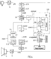
- FIG. 5 shows a system arrangement for multi-channel hands-free talking using the example of a three-channel arrangement.
- a microphone M1, M2, M3 is available for each local subscriber.
- the location of the respective microphone M1, M2, M3 corresponds to the location of the respective loudspeaker at the far end of the transmission system, at which a corresponding hands-free arrangement is located.
- Each remote subscriber is accordingly reproduced via a loudspeaker L1, L2, L3, whose location reflects the location of the participant at the far end.
- the D / A converters connected upstream of the loudspeakers L1, L2, L3 and the A / D converters connected downstream of the microphones M1, M2, M3 are not shown in FIG. 5 for reasons of clarity.
- the amplification factors for the transmission signals VS1, VS2, VS3 are calculated separately for each microphone M1, M2, M3. This enables both individual noise suppression and optimal adaptation to the speaker.
- the respective short-term mean values ysam1, ysam2, ysam3 are formed from the sampled values of the transmission signals y1 (k), y2 (k), y3 (k), and the long-term mean value of the transmission signals ylam is obtained by integrating the sum of these short-term mean values.
- the respective short-term mean values xsam1, xsam2, xsam3 are formed from the sampled values of the received signals x1 (k), x2 (k), x3 (k) by forming the amount and subsequent integration, and the long-term mean value of the received signals is produced by integrating the sum of these short-term mean values xlam.
- the largest short-term mean value xmax and its origin location are first determined from the short-term mean values of the received signals xsam1, xsam2, xsam3 and the origin of the location using the evaluation circuit 7.
- a suitable reception signal is thus obtained from a loudspeaker which is currently active for calculating the coupling factor.
- the difference between the largest short-term mean value xmax and the individual short-term mean values xsam1, xsam2, xsam3 smaller than with only one active loudspeaker, since a microphone then receives several loudspeaker signals. This difference must exceed a certain threshold xdiff so that a correct coupling factor calculation can be carried out.
- the difference ⁇ xsam - xmax can also be formed.
- a small difference indicates that the sum ⁇ xsam is mainly generated by xmax. The means that only one loudspeaker is active and thus a reliable calculation of the coupling factor is possible. Equations (7a) or (7b) then apply to the release of the calculation:
- the coupling factors are calculated separately for each microphone.
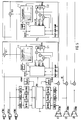
- 6 shows a detailed representation of the coupling estimator 2.1 for the first microphone M1, a representation of the coupling estimator 2.2 for the second microphone M2 and a representation of the coupling estimator 2.n for the nth microphone Mn.
- the current coupling factors are calculated by means of the min detect minimum value detectors shown in FIG. 4 and described in more detail.
- xsam1 thrs12 dlm 1-2.
- xsam2 thrs13 dlm 1-3.
- the maximum value is determined by a first maximum value decider 3.1 for the first microphone M1 and correspondingly a second maximum value decider 3.2 for the second microphone M2 weighted coupling factors are determined and this is then used to briefly shift the transmission characteristic of the respective compander 1.1, 1.2 and thus determine the respective transmission gain VS1, VS2.
- the largest current coupling for shifting the transmission characteristic always takes effect, so that the stability of the transmission systems is guaranteed. Since the coupling factors dlm 1-1 to dlm 3-3 are determined individually, the least possible influence on the intercom is achieved.
- the long-term mean value of the transmit signal ylam determines the gain in the receive branch VE. As shown in Fig. 5, the gain is set uniformly for all transmission branches. However, it is also possible to set the gains for each reception branch separately via the long-term mean values of the individual transmission branches ylam1, ylam2, ylam 3. This is particularly useful if the places of the participants are far apart and the noise situation is different for each place.
- a special case of multi-channel hands-free calling is stereophonic hands-free calling with a hands-free device according to FIG. 7.
- the loudspeakers LL, LR and microphones Ml, MR used for the left and right channels are arranged symmetrically. Different speaker locations are represented by level and delay differences between the left and right signals.
- the channels of the receiving branch and the channels of the transmitting branch must be operated with the same amplification VE, VS in the case of stereophonic hands-free speaking.
- the short-term mean values ysamL, ysamR are formed by integrating the amounts of the samples of the transmission signals y (k) L, y (k) R and compared with one another by a maximum value decider 8.
- the larger value ysammax is used to calculate the current coupling factor dlm and after integration as long-term mean value ylam is used to shift the transmission characteristic of compander 1 and thus to set the transmission gain VS.
- the short-term mean values xsamL, xsamR are formed by integrating the amounts of the samples of the received signals x (k) L, x (k) R and compared with one another by a further maximum value decider 9.
- the larger value xsammax is used to calculate the current coupling factor dlm and to weight the coupling factor dlm to determine the shift in the transmission characteristic of compander 1, and after integration as a long-term mean xlam is used as a measure of the received noise level.
- the method according to the invention can be implemented with less effort in comparison to known multichannel hands-free methods with FIR filters.
- the calculation of the individual coupling factors is much easier than the determination of the coefficients of the FIR filters.
- shifting the transmission characteristic of the respective compander 1.1, 1.2 which is determined by the weighted coupling factors, see Fig. 5, it is achieved that ambient noise and echoes are completely attenuated.
- the response threshold of the transmission characteristic of the compander is determined by the ambient noise, and in the case of acoustic echoes the transmission characteristic is automatically shifted briefly to the right, as indicated in the figures, so that the echoes are not transmitted.
Landscapes
- Engineering & Computer Science (AREA)
- Signal Processing (AREA)
- Circuit For Audible Band Transducer (AREA)
- Interconnected Communication Systems, Intercoms, And Interphones (AREA)
- Cable Transmission Systems, Equalization Of Radio And Reduction Of Echo (AREA)
- Telephone Function (AREA)
- Two-Way Televisions, Distribution Of Moving Picture Or The Like (AREA)
- Communication Control (AREA)
Applications Claiming Priority (2)
| Application Number | Priority Date | Filing Date | Title |
|---|---|---|---|
| DE19517469A DE19517469A1 (de) | 1995-05-12 | 1995-05-12 | Freisprechverfahren für ein mehrkanaliges Übertragungssystem |
| DE19517469 | 1995-05-12 |
Publications (3)
| Publication Number | Publication Date |
|---|---|
| EP0742664A2 true EP0742664A2 (fr) | 1996-11-13 |
| EP0742664A3 EP0742664A3 (fr) | 2003-07-23 |
| EP0742664B1 EP0742664B1 (fr) | 2004-12-22 |
Family
ID=7761760
Family Applications (1)
| Application Number | Title | Priority Date | Filing Date |
|---|---|---|---|
| EP96106492A Expired - Lifetime EP0742664B1 (fr) | 1995-05-12 | 1996-04-25 | Méthode pour parler à main levée pour un système de transmission à canaux multiples |
Country Status (7)
| Country | Link |
|---|---|
| US (1) | US5901230A (fr) |
| EP (1) | EP0742664B1 (fr) |
| JP (1) | JPH0927775A (fr) |
| AT (1) | ATE285654T1 (fr) |
| AU (1) | AU710394B2 (fr) |
| CA (1) | CA2176305A1 (fr) |
| DE (2) | DE19517469A1 (fr) |
Cited By (3)
| Publication number | Priority date | Publication date | Assignee | Title |
|---|---|---|---|---|
| DE19801389A1 (de) * | 1998-01-16 | 1999-07-22 | Cit Alcatel | Verfahren zur Echounterdrückung mit adaptiven FIR-Filtern |
| GB2320996B (en) * | 1996-11-07 | 2001-12-05 | Deutsche Telekom Ag | Method for multi-channel sound transmission |
| EP0949767A3 (fr) * | 1998-04-09 | 2003-11-12 | Alcatel | Annuleur d'échos à canaux multiple avec compresseur-extenseur |
Families Citing this family (43)
| Publication number | Priority date | Publication date | Assignee | Title |
|---|---|---|---|---|
| DE19635878A1 (de) * | 1996-09-04 | 1998-03-05 | Deutsche Telekom Ag | Vorrichtung zur Verbesserung des Sendesignals einer Echoreduktionseinrichtung |
| FR2763774B1 (fr) * | 1997-05-21 | 1999-08-06 | France Telecom | Procede et dispositif de reduction d'echo acoustique multivoies et de spatialisation sonore |
| DE19850271A1 (de) * | 1998-10-31 | 2000-05-04 | Alcatel Sa | Verfahren zur Bestimmung eines Echokopplungsfaktors und der Echolaufzeit in einem bidirektionalen Telekommunikationssystem |
| DE19850272A1 (de) * | 1998-10-31 | 2000-05-04 | Alcatel Sa | Verfahren zur Verbesserung der Echounterdrückung in einem Telekommunikaionssystem |
| GB9929442D0 (en) * | 1999-12-13 | 2000-02-09 | Element 14 Inc | Interference cancellaton equipment |
| US7027607B2 (en) * | 2000-09-22 | 2006-04-11 | Gn Resound A/S | Hearing aid with adaptive microphone matching |
| US7522734B2 (en) * | 2000-10-10 | 2009-04-21 | The Board Of Trustees Of The Leland Stanford Junior University | Distributed acoustic reverberation for audio collaboration |
| US20020054685A1 (en) * | 2000-11-09 | 2002-05-09 | Carlos Avendano | System for suppressing acoustic echoes and interferences in multi-channel audio systems |
| JP4094455B2 (ja) * | 2003-03-05 | 2008-06-04 | 松下電器産業株式会社 | ハウリング抑制装置 |
| US20050132273A1 (en) * | 2003-12-11 | 2005-06-16 | International Business Machines Corporation | Amending a session document during a presentation |
| US7162692B2 (en) | 2003-12-11 | 2007-01-09 | International Business Machines Corporation | Differential dynamic content delivery |
| US7634412B2 (en) * | 2003-12-11 | 2009-12-15 | Nuance Communications, Inc. | Creating a voice response grammar from a user grammar |
| US20050132271A1 (en) * | 2003-12-11 | 2005-06-16 | International Business Machines Corporation | Creating a session document from a presentation document |
| US9378187B2 (en) * | 2003-12-11 | 2016-06-28 | International Business Machines Corporation | Creating a presentation document |
| US20050132274A1 (en) * | 2003-12-11 | 2005-06-16 | International Business Machine Corporation | Creating a presentation document |
| US7890848B2 (en) | 2004-01-13 | 2011-02-15 | International Business Machines Corporation | Differential dynamic content delivery with alternative content presentation |
| US8001454B2 (en) | 2004-01-13 | 2011-08-16 | International Business Machines Corporation | Differential dynamic content delivery with presentation control instructions |
| US8499232B2 (en) * | 2004-01-13 | 2013-07-30 | International Business Machines Corporation | Differential dynamic content delivery with a participant alterable session copy of a user profile |
| US7571380B2 (en) * | 2004-01-13 | 2009-08-04 | International Business Machines Corporation | Differential dynamic content delivery with a presenter-alterable session copy of a user profile |
| US8954844B2 (en) * | 2004-01-13 | 2015-02-10 | Nuance Communications, Inc. | Differential dynamic content delivery with text display in dependence upon sound level |
| US7287221B2 (en) | 2004-01-13 | 2007-10-23 | International Business Machines Corporation | Differential dynamic content delivery with text display in dependence upon sound level |
| US7430707B2 (en) | 2004-01-13 | 2008-09-30 | International Business Machines Corporation | Differential dynamic content delivery with device controlling action |
| US7567908B2 (en) * | 2004-01-13 | 2009-07-28 | International Business Machines Corporation | Differential dynamic content delivery with text display in dependence upon simultaneous speech |
| FR2868036B1 (fr) * | 2004-03-24 | 2006-06-02 | Eca Societe Par Actions Simpli | Dispositif de mise a l'eau et de recuperation d'un vehicule submersible |
| US7519659B2 (en) * | 2004-04-26 | 2009-04-14 | International Business Machines Corporation | Dynamic media content for collaborators |
| US7831906B2 (en) * | 2004-04-26 | 2010-11-09 | International Business Machines Corporation | Virtually bound dynamic media content for collaborators |
| US7827239B2 (en) * | 2004-04-26 | 2010-11-02 | International Business Machines Corporation | Dynamic media content for collaborators with client environment information in dynamic client contexts |
| US7519683B2 (en) * | 2004-04-26 | 2009-04-14 | International Business Machines Corporation | Dynamic media content for collaborators with client locations in dynamic client contexts |
| US7487208B2 (en) * | 2004-07-08 | 2009-02-03 | International Business Machines Corporation | Differential dynamic content delivery to alternate display device locations |
| US8185814B2 (en) * | 2004-07-08 | 2012-05-22 | International Business Machines Corporation | Differential dynamic delivery of content according to user expressions of interest |
| US7921362B2 (en) * | 2004-07-08 | 2011-04-05 | International Business Machines Corporation | Differential dynamic delivery of presentation previews |
| US7519904B2 (en) * | 2004-07-08 | 2009-04-14 | International Business Machines Corporation | Differential dynamic delivery of content to users not in attendance at a presentation |
| US7428698B2 (en) * | 2004-07-08 | 2008-09-23 | International Business Machines Corporation | Differential dynamic delivery of content historically likely to be viewed |
| US7426538B2 (en) * | 2004-07-13 | 2008-09-16 | International Business Machines Corporation | Dynamic media content for collaborators with VOIP support for client communications |
| US9167087B2 (en) * | 2004-07-13 | 2015-10-20 | International Business Machines Corporation | Dynamic media content for collaborators including disparate location representations |
| US7487209B2 (en) * | 2004-07-13 | 2009-02-03 | International Business Machines Corporation | Delivering dynamic media content for collaborators to purposeful devices |
| US20060015557A1 (en) * | 2004-07-13 | 2006-01-19 | International Business Machines Corporation | Dynamic media content for collaborator groups |
| US7475340B2 (en) * | 2005-03-24 | 2009-01-06 | International Business Machines Corporation | Differential dynamic content delivery with indications of interest from non-participants |
| US7523388B2 (en) * | 2005-03-31 | 2009-04-21 | International Business Machines Corporation | Differential dynamic content delivery with a planned agenda |
| US7493556B2 (en) * | 2005-03-31 | 2009-02-17 | International Business Machines Corporation | Differential dynamic content delivery with a session document recreated in dependence upon an interest of an identified user participant |
| US8594320B2 (en) * | 2005-04-19 | 2013-11-26 | (Epfl) Ecole Polytechnique Federale De Lausanne | Hybrid echo and noise suppression method and device in a multi-channel audio signal |
| FR2888458A1 (fr) * | 2005-07-11 | 2007-01-12 | France Telecom | Procede et dispositif de prise de son, notamment dans des terminaux telephoniques en "mains libres" |
| FR2888449A1 (fr) * | 2005-07-11 | 2007-01-12 | France Telecom | Procede et dispositif de traitement d'echos forts, notamment dans des terminaux telephoniques en "mains libres" |
Family Cites Families (13)
| Publication number | Priority date | Publication date | Assignee | Title |
|---|---|---|---|---|
| HU169185B (fr) * | 1974-06-05 | 1976-10-28 | ||
| DE3724346A1 (de) * | 1987-05-15 | 1988-11-24 | Standard Elektrik Lorenz Ag | Schaltungsanordnung zur dynamiksteuerung |
| EP0290952B1 (fr) * | 1987-05-15 | 1992-11-04 | Alcatel SEL Aktiengesellschaft | Montage pour commande de la parole pour un terminal de télécommunication |
| AT393426B (de) * | 1987-09-03 | 1991-10-25 | Siemens Ag Oesterreich | Freisprechanlage |
| DE4111820A1 (de) * | 1990-09-12 | 1992-03-19 | Hagenuk Telecom Gmbh | Schaltungsanordnung zur vermeidung von akustischen rueckkopplungen, insbesondere bei lauthoer-freisprech-telefonen |
| JP2792252B2 (ja) * | 1991-03-14 | 1998-09-03 | 日本電気株式会社 | 多チャンネルエコー除去方法および装置 |
| DE4130045A1 (de) * | 1991-09-10 | 1993-03-18 | Standard Elektrik Lorenz Ag | Schaltungsanordnung zur dynamiksteuerung eines sprachendgeraetes |
| DE4222465C2 (de) * | 1992-07-08 | 1994-08-04 | Siemens Ag | Regelungsverfahren für zu akustischen Rückkopplungen neigende elektroakustische Systeme |
| DE4229912A1 (de) * | 1992-09-08 | 1994-03-10 | Sel Alcatel Ag | Verfahren zum Verbessern der Übertragungseigenschaften einer elektroakustischen Anlage |
| DE4305256A1 (de) * | 1993-02-20 | 1994-08-25 | Sel Alcatel Ag | Verfahren zum Verbessern der akustischen Rückhördämpfung von elektroakustischen Anlagen |
| JPH084243B2 (ja) * | 1993-05-31 | 1996-01-17 | 日本電気株式会社 | 多チャンネルエコー除去方法および装置 |
| DE4337653A1 (de) * | 1993-11-04 | 1995-05-11 | Deutsche Bundespost Telekom | Verfahren und Schaltungsanordnung zur Verbesserung der Qualität der Sprachkommunikation in Freisprecheinrichtungen |
| DE4407102C1 (de) * | 1994-03-03 | 1995-03-23 | Siemens Ag | Regelungsverfahren und -anordnung für ein zu akustischen Rückkopplungen neigendes elektroakustisches System |
-
1995
- 1995-05-12 DE DE19517469A patent/DE19517469A1/de not_active Withdrawn
-
1996
- 1996-04-25 DE DE59611166T patent/DE59611166D1/de not_active Expired - Fee Related
- 1996-04-25 AT AT96106492T patent/ATE285654T1/de not_active IP Right Cessation
- 1996-04-25 EP EP96106492A patent/EP0742664B1/fr not_active Expired - Lifetime
- 1996-05-07 AU AU52111/96A patent/AU710394B2/en not_active Ceased
- 1996-05-09 US US08/647,306 patent/US5901230A/en not_active Expired - Fee Related
- 1996-05-10 CA CA002176305A patent/CA2176305A1/fr not_active Abandoned
- 1996-05-13 JP JP8118082A patent/JPH0927775A/ja active Pending
Cited By (4)
| Publication number | Priority date | Publication date | Assignee | Title |
|---|---|---|---|---|
| GB2320996B (en) * | 1996-11-07 | 2001-12-05 | Deutsche Telekom Ag | Method for multi-channel sound transmission |
| DE19801389A1 (de) * | 1998-01-16 | 1999-07-22 | Cit Alcatel | Verfahren zur Echounterdrückung mit adaptiven FIR-Filtern |
| US6493448B1 (en) | 1998-01-16 | 2002-12-10 | Alcatel | Process for echo suppression with adaptive fir filters |
| EP0949767A3 (fr) * | 1998-04-09 | 2003-11-12 | Alcatel | Annuleur d'échos à canaux multiple avec compresseur-extenseur |
Also Published As
| Publication number | Publication date |
|---|---|
| JPH0927775A (ja) | 1997-01-28 |
| AU5211196A (en) | 1996-11-21 |
| EP0742664A3 (fr) | 2003-07-23 |
| ATE285654T1 (de) | 2005-01-15 |
| DE59611166D1 (de) | 2005-01-27 |
| DE19517469A1 (de) | 1996-11-14 |
| EP0742664B1 (fr) | 2004-12-22 |
| CA2176305A1 (fr) | 1996-11-13 |
| AU710394B2 (en) | 1999-09-16 |
| US5901230A (en) | 1999-05-04 |
Similar Documents
| Publication | Publication Date | Title |
|---|---|---|
| EP0742664B1 (fr) | Méthode pour parler à main levée pour un système de transmission à canaux multiples | |
| EP0698986B1 (fr) | Procédé pour la compensation adaptative d'écho | |
| DE69632851T2 (de) | Akustischer Teilband-Echokompensator | |
| DE69431923T2 (de) | Adaptiver algorithmus mit variablen blocklängen für rauschrobuste akustische echokompensation | |
| EP0290952B1 (fr) | Montage pour commande de la parole pour un terminal de télécommunication | |
| DE69332309T2 (de) | Ausfallgesichertes betriebsverfahren in einem lautfernsprechsystem | |
| DE60108401T2 (de) | System zur erhöhung der sprachqualität | |
| DE19848588B4 (de) | Nichtlinearer Prozessor für akustische Echokompensatoren | |
| EP0614304A1 (fr) | Procédé pour améliorer l'affaiblissement du signal local sur des dispositifs électro-acoustiques | |
| DE69604901T2 (de) | Lautsprecher-verstärkungseinstellung für ein freisprech-telekommunikationsendgerät | |
| DE19806015C2 (de) | Verfahren zur Verbesserung der akustischen Rückhördämpfung in Freisprecheinrichtungen | |
| EP0797339B1 (fr) | Procédé et circuit pour améliorer la caractéristique de transmission d'une liaison de télécommunications perturbée par un écho | |
| EP1155561B1 (fr) | Dispositif et procede de suppression de bruit dans des installations telephoniques | |
| EP0843455B1 (fr) | Procédé et dispositif d'annulation adaptive d'écho | |
| DE69132988T2 (de) | Verfahren für aktive rückkopplunglsunterdrückung | |
| EP0642251B1 (fr) | Procédé pour la commutation automatique de la direction de la parole, et circuit pour la mise en oeuvre du procédé | |
| DE3839627C2 (de) | Fernsprechendgerät | |
| EP0776118B1 (fr) | Procédé d'annulation d'écho | |
| DE19753224C2 (de) | Verfahren und Vorrichtung zur Echounterdrückung bei einer Freisprecheinrichtung, insbesondere für ein Telefon | |
| DE19639580C2 (de) | Vorrichtung zur Reduktion akustischer Echos | |
| DE19923601C1 (de) | Echokompensationseinrichtung | |
| DE3724346A1 (de) | Schaltungsanordnung zur dynamiksteuerung | |
| EP0902416B1 (fr) | Procédé et dispositif pour reconnaitre une entrée de parole pendant la diffusion d'une annonce | |
| EP0999655B1 (fr) | Procédé pour la détermination du facteur de couplage d'écho et de retard de propagation d'écho dans un système bidirectionel de télécommunications | |
| EP0768789A2 (fr) | Méthode et agencement de circuit pour la détection de la parole d'abonné eloigné dans un terminal téléphonique |
Legal Events
| Date | Code | Title | Description |
|---|---|---|---|
| PUAI | Public reference made under article 153(3) epc to a published international application that has entered the european phase |
Free format text: ORIGINAL CODE: 0009012 |
|
| AK | Designated contracting states |
Kind code of ref document: A2 Designated state(s): AT BE CH DE ES FR GB IT LI NL SE |
|
| PUAL | Search report despatched |
Free format text: ORIGINAL CODE: 0009013 |
|
| RIC1 | Information provided on ipc code assigned before grant |
Ipc: 7H 04M 1/60 B Ipc: 7H 04M 9/08 B Ipc: 7H 04M 9/00 A |
|
| AK | Designated contracting states |
Designated state(s): AT BE CH DE ES FR GB IT LI NL SE |
|
| 17P | Request for examination filed |
Effective date: 20030801 |
|
| 17Q | First examination report despatched |
Effective date: 20030915 |
|
| GRAP | Despatch of communication of intention to grant a patent |
Free format text: ORIGINAL CODE: EPIDOSNIGR1 |
|
| GRAS | Grant fee paid |
Free format text: ORIGINAL CODE: EPIDOSNIGR3 |
|
| GRAA | (expected) grant |
Free format text: ORIGINAL CODE: 0009210 |
|
| RAP1 | Party data changed (applicant data changed or rights of an application transferred) |
Owner name: ALCATEL |
|
| AK | Designated contracting states |
Kind code of ref document: B1 Designated state(s): AT BE CH DE ES FR GB IT LI NL SE |
|
| PG25 | Lapsed in a contracting state [announced via postgrant information from national office to epo] |
Ref country code: NL Free format text: LAPSE BECAUSE OF FAILURE TO SUBMIT A TRANSLATION OF THE DESCRIPTION OR TO PAY THE FEE WITHIN THE PRESCRIBED TIME-LIMIT Effective date: 20041222 Ref country code: IT Free format text: LAPSE BECAUSE OF FAILURE TO SUBMIT A TRANSLATION OF THE DESCRIPTION OR TO PAY THE FEE WITHIN THE PRESCRIBED TIME-LIMIT;WARNING: LAPSES OF ITALIAN PATENTS WITH EFFECTIVE DATE BEFORE 2007 MAY HAVE OCCURRED AT ANY TIME BEFORE 2007. THE CORRECT EFFECTIVE DATE MAY BE DIFFERENT FROM THE ONE RECORDED. Effective date: 20041222 |
|
| REG | Reference to a national code |
Ref country code: GB Ref legal event code: FG4D Free format text: NOT ENGLISH |
|
| REG | Reference to a national code |
Ref country code: CH Ref legal event code: EP |
|
| GBT | Gb: translation of ep patent filed (gb section 77(6)(a)/1977) |
Effective date: 20041222 |
|
| REF | Corresponds to: |
Ref document number: 59611166 Country of ref document: DE Date of ref document: 20050127 Kind code of ref document: P |
|
| PG25 | Lapsed in a contracting state [announced via postgrant information from national office to epo] |
Ref country code: SE Free format text: LAPSE BECAUSE OF FAILURE TO SUBMIT A TRANSLATION OF THE DESCRIPTION OR TO PAY THE FEE WITHIN THE PRESCRIBED TIME-LIMIT Effective date: 20050322 |
|
| PG25 | Lapsed in a contracting state [announced via postgrant information from national office to epo] |
Ref country code: ES Free format text: LAPSE BECAUSE OF FAILURE TO SUBMIT A TRANSLATION OF THE DESCRIPTION OR TO PAY THE FEE WITHIN THE PRESCRIBED TIME-LIMIT Effective date: 20050402 |
|
| PG25 | Lapsed in a contracting state [announced via postgrant information from national office to epo] |
Ref country code: AT Free format text: LAPSE BECAUSE OF NON-PAYMENT OF DUE FEES Effective date: 20050425 |
|
| PG25 | Lapsed in a contracting state [announced via postgrant information from national office to epo] |
Ref country code: LI Free format text: LAPSE BECAUSE OF NON-PAYMENT OF DUE FEES Effective date: 20050430 Ref country code: CH Free format text: LAPSE BECAUSE OF NON-PAYMENT OF DUE FEES Effective date: 20050430 Ref country code: BE Free format text: LAPSE BECAUSE OF NON-PAYMENT OF DUE FEES Effective date: 20050430 |
|
| NLV1 | Nl: lapsed or annulled due to failure to fulfill the requirements of art. 29p and 29m of the patents act | ||
| PLBE | No opposition filed within time limit |
Free format text: ORIGINAL CODE: 0009261 |
|
| STAA | Information on the status of an ep patent application or granted ep patent |
Free format text: STATUS: NO OPPOSITION FILED WITHIN TIME LIMIT |
|
| BERE | Be: lapsed |
Owner name: ALCATEL Effective date: 20050430 |
|
| ET | Fr: translation filed | ||
| 26N | No opposition filed |
Effective date: 20050923 |
|
| REG | Reference to a national code |
Ref country code: CH Ref legal event code: PL |
|
| PGFP | Annual fee paid to national office [announced via postgrant information from national office to epo] |
Ref country code: DE Payment date: 20070423 Year of fee payment: 12 |
|
| BERE | Be: lapsed |
Owner name: *ALCATEL Effective date: 20050430 |
|
| PGFP | Annual fee paid to national office [announced via postgrant information from national office to epo] |
Ref country code: FR Payment date: 20070416 Year of fee payment: 12 |
|
| PGFP | Annual fee paid to national office [announced via postgrant information from national office to epo] |
Ref country code: GB Payment date: 20080530 Year of fee payment: 13 |
|
| PG25 | Lapsed in a contracting state [announced via postgrant information from national office to epo] |
Ref country code: DE Free format text: LAPSE BECAUSE OF NON-PAYMENT OF DUE FEES Effective date: 20081101 |
|
| REG | Reference to a national code |
Ref country code: FR Ref legal event code: ST Effective date: 20081231 |
|
| PG25 | Lapsed in a contracting state [announced via postgrant information from national office to epo] |
Ref country code: FR Free format text: LAPSE BECAUSE OF NON-PAYMENT OF DUE FEES Effective date: 20080430 |
|
| GBPC | Gb: european patent ceased through non-payment of renewal fee |
Effective date: 20090425 |
|
| PG25 | Lapsed in a contracting state [announced via postgrant information from national office to epo] |
Ref country code: GB Free format text: LAPSE BECAUSE OF NON-PAYMENT OF DUE FEES Effective date: 20090425 |