EP0743165A2 - Verfahren und Vorrichtung zum Formen verstärkter thermoplastischer Verbundwerkstoffe - Google Patents
Verfahren und Vorrichtung zum Formen verstärkter thermoplastischer Verbundwerkstoffe Download PDFInfo
- Publication number
- EP0743165A2 EP0743165A2 EP96303489A EP96303489A EP0743165A2 EP 0743165 A2 EP0743165 A2 EP 0743165A2 EP 96303489 A EP96303489 A EP 96303489A EP 96303489 A EP96303489 A EP 96303489A EP 0743165 A2 EP0743165 A2 EP 0743165A2
- Authority
- EP
- European Patent Office
- Prior art keywords
- fibers
- preform
- thermoplastic
- resin matrix
- screen
- Prior art date
- Legal status (The legal status is an assumption and is not a legal conclusion. Google has not performed a legal analysis and makes no representation as to the accuracy of the status listed.)
- Granted
Links
- 238000000034 method Methods 0.000 title claims abstract description 50
- 229920001169 thermoplastic Polymers 0.000 title claims description 45
- 239000004416 thermosoftening plastic Substances 0.000 title claims description 45
- 238000000465 moulding Methods 0.000 title description 3
- 239000000835 fiber Substances 0.000 claims abstract description 145
- 230000027455 binding Effects 0.000 claims abstract description 59
- 239000012783 reinforcing fiber Substances 0.000 claims abstract description 50
- 239000011159 matrix material Substances 0.000 claims abstract description 48
- 229920002430 Fibre-reinforced plastic Polymers 0.000 claims abstract description 42
- 239000011151 fibre-reinforced plastic Substances 0.000 claims abstract description 42
- 229920005989 resin Polymers 0.000 claims abstract description 39
- 239000011347 resin Substances 0.000 claims abstract description 39
- 239000012530 fluid Substances 0.000 claims abstract description 14
- 239000000203 mixture Substances 0.000 claims abstract description 8
- 239000002002 slurry Substances 0.000 claims description 39
- 238000002844 melting Methods 0.000 claims description 25
- 230000008018 melting Effects 0.000 claims description 25
- 238000010438 heat treatment Methods 0.000 claims description 18
- 229920000728 polyester Polymers 0.000 claims description 10
- 229920005992 thermoplastic resin Polymers 0.000 claims description 9
- 230000000295 complement effect Effects 0.000 claims description 8
- 238000001816 cooling Methods 0.000 claims description 8
- 239000007788 liquid Substances 0.000 claims description 3
- 238000002156 mixing Methods 0.000 claims description 3
- 229920003023 plastic Polymers 0.000 claims description 3
- 239000004033 plastic Substances 0.000 claims description 3
- 238000009827 uniform distribution Methods 0.000 claims 2
- 238000000151 deposition Methods 0.000 abstract 1
- 239000000463 material Substances 0.000 description 23
- 230000008569 process Effects 0.000 description 13
- 230000005672 electromagnetic field Effects 0.000 description 12
- XLYOFNOQVPJJNP-UHFFFAOYSA-N water Substances O XLYOFNOQVPJJNP-UHFFFAOYSA-N 0.000 description 11
- 239000012815 thermoplastic material Substances 0.000 description 9
- -1 polypropylene Polymers 0.000 description 8
- 239000006185 dispersion Substances 0.000 description 6
- 230000008901 benefit Effects 0.000 description 5
- 239000004743 Polypropylene Substances 0.000 description 4
- 238000001035 drying Methods 0.000 description 4
- 229920001778 nylon Polymers 0.000 description 4
- 229920001155 polypropylene Polymers 0.000 description 4
- OKTJSMMVPCPJKN-UHFFFAOYSA-N Carbon Chemical compound [C] OKTJSMMVPCPJKN-UHFFFAOYSA-N 0.000 description 3
- 239000004677 Nylon Substances 0.000 description 3
- 239000004698 Polyethylene Substances 0.000 description 3
- 230000009471 action Effects 0.000 description 3
- 230000003213 activating effect Effects 0.000 description 3
- 239000011230 binding agent Substances 0.000 description 3
- 230000005294 ferromagnetic effect Effects 0.000 description 3
- 239000003302 ferromagnetic material Substances 0.000 description 3
- 239000002657 fibrous material Substances 0.000 description 3
- 239000000945 filler Substances 0.000 description 3
- 239000011521 glass Substances 0.000 description 3
- 239000002245 particle Substances 0.000 description 3
- 229920000573 polyethylene Polymers 0.000 description 3
- XEEYBQQBJWHFJM-UHFFFAOYSA-N Iron Chemical compound [Fe] XEEYBQQBJWHFJM-UHFFFAOYSA-N 0.000 description 2
- UQSXHKLRYXJYBZ-UHFFFAOYSA-N Iron oxide Chemical compound [Fe]=O UQSXHKLRYXJYBZ-UHFFFAOYSA-N 0.000 description 2
- PXHVJJICTQNCMI-UHFFFAOYSA-N Nickel Chemical compound [Ni] PXHVJJICTQNCMI-UHFFFAOYSA-N 0.000 description 2
- PPBRXRYQALVLMV-UHFFFAOYSA-N Styrene Chemical compound C=CC1=CC=CC=C1 PPBRXRYQALVLMV-UHFFFAOYSA-N 0.000 description 2
- 150000001875 compounds Chemical class 0.000 description 2
- 239000010439 graphite Substances 0.000 description 2
- 229910002804 graphite Inorganic materials 0.000 description 2
- 238000002347 injection Methods 0.000 description 2
- 239000007924 injection Substances 0.000 description 2
- 238000004519 manufacturing process Methods 0.000 description 2
- 230000007246 mechanism Effects 0.000 description 2
- 239000000155 melt Substances 0.000 description 2
- 230000004048 modification Effects 0.000 description 2
- 238000012986 modification Methods 0.000 description 2
- 238000009987 spinning Methods 0.000 description 2
- 238000001721 transfer moulding Methods 0.000 description 2
- 238000009834 vaporization Methods 0.000 description 2
- 230000008016 vaporization Effects 0.000 description 2
- 229920006362 Teflon® Polymers 0.000 description 1
- 239000000853 adhesive Substances 0.000 description 1
- 230000001070 adhesive effect Effects 0.000 description 1
- 239000000956 alloy Substances 0.000 description 1
- 229910045601 alloy Inorganic materials 0.000 description 1
- 230000004075 alteration Effects 0.000 description 1
- 229910052799 carbon Inorganic materials 0.000 description 1
- 229910017052 cobalt Inorganic materials 0.000 description 1
- 239000010941 cobalt Substances 0.000 description 1
- GUTLYIVDDKVIGB-UHFFFAOYSA-N cobalt atom Chemical compound [Co] GUTLYIVDDKVIGB-UHFFFAOYSA-N 0.000 description 1
- 239000002131 composite material Substances 0.000 description 1
- 238000000748 compression moulding Methods 0.000 description 1
- 238000006073 displacement reaction Methods 0.000 description 1
- 238000009826 distribution Methods 0.000 description 1
- 230000005674 electromagnetic induction Effects 0.000 description 1
- 239000011152 fibreglass Substances 0.000 description 1
- 239000008240 homogeneous mixture Substances 0.000 description 1
- 229910052742 iron Inorganic materials 0.000 description 1
- 230000001788 irregular Effects 0.000 description 1
- 239000002184 metal Substances 0.000 description 1
- 229910052751 metal Inorganic materials 0.000 description 1
- 229910052759 nickel Inorganic materials 0.000 description 1
- 238000010791 quenching Methods 0.000 description 1
- 230000000171 quenching effect Effects 0.000 description 1
- 230000001105 regulatory effect Effects 0.000 description 1
- 239000002990 reinforced plastic Substances 0.000 description 1
- 230000003014 reinforcing effect Effects 0.000 description 1
- 238000009877 rendering Methods 0.000 description 1
Images


Classifications
-
- B—PERFORMING OPERATIONS; TRANSPORTING
- B29—WORKING OF PLASTICS; WORKING OF SUBSTANCES IN A PLASTIC STATE IN GENERAL
- B29C—SHAPING OR JOINING OF PLASTICS; SHAPING OF MATERIAL IN A PLASTIC STATE, NOT OTHERWISE PROVIDED FOR; AFTER-TREATMENT OF THE SHAPED PRODUCTS, e.g. REPAIRING
- B29C70/00—Shaping composites, i.e. plastics material comprising reinforcements, fillers or preformed parts, e.g. inserts
- B29C70/04—Shaping composites, i.e. plastics material comprising reinforcements, fillers or preformed parts, e.g. inserts comprising reinforcements only, e.g. self-reinforcing plastics
- B29C70/28—Shaping operations therefor
- B29C70/54—Component parts, details or accessories; Auxiliary operations, e.g. feeding or storage of prepregs or SMC after impregnation or during ageing
- B29C70/543—Fixing the position or configuration of fibrous reinforcements before or during moulding
-
- B—PERFORMING OPERATIONS; TRANSPORTING
- B29—WORKING OF PLASTICS; WORKING OF SUBSTANCES IN A PLASTIC STATE IN GENERAL
- B29B—PREPARATION OR PRETREATMENT OF THE MATERIAL TO BE SHAPED; MAKING GRANULES OR PREFORMS; RECOVERY OF PLASTICS OR OTHER CONSTITUENTS OF WASTE MATERIAL CONTAINING PLASTICS
- B29B11/00—Making preforms
- B29B11/14—Making preforms characterised by structure or composition
- B29B11/16—Making preforms characterised by structure or composition comprising fillers or reinforcement
-
- B—PERFORMING OPERATIONS; TRANSPORTING
- B29—WORKING OF PLASTICS; WORKING OF SUBSTANCES IN A PLASTIC STATE IN GENERAL
- B29C—SHAPING OR JOINING OF PLASTICS; SHAPING OF MATERIAL IN A PLASTIC STATE, NOT OTHERWISE PROVIDED FOR; AFTER-TREATMENT OF THE SHAPED PRODUCTS, e.g. REPAIRING
- B29C70/00—Shaping composites, i.e. plastics material comprising reinforcements, fillers or preformed parts, e.g. inserts
- B29C70/04—Shaping composites, i.e. plastics material comprising reinforcements, fillers or preformed parts, e.g. inserts comprising reinforcements only, e.g. self-reinforcing plastics
- B29C70/28—Shaping operations therefor
- B29C70/30—Shaping by lay-up, i.e. applying fibres, tape or broadsheet on a mould, former or core; Shaping by spray-up, i.e. spraying of fibres on a mould, former or core
- B29C70/305—Spray-up of reinforcing fibres with or without matrix to form a non-coherent mat in or on a mould
-
- B—PERFORMING OPERATIONS; TRANSPORTING
- B29—WORKING OF PLASTICS; WORKING OF SUBSTANCES IN A PLASTIC STATE IN GENERAL
- B29C—SHAPING OR JOINING OF PLASTICS; SHAPING OF MATERIAL IN A PLASTIC STATE, NOT OTHERWISE PROVIDED FOR; AFTER-TREATMENT OF THE SHAPED PRODUCTS, e.g. REPAIRING
- B29C70/00—Shaping composites, i.e. plastics material comprising reinforcements, fillers or preformed parts, e.g. inserts
- B29C70/04—Shaping composites, i.e. plastics material comprising reinforcements, fillers or preformed parts, e.g. inserts comprising reinforcements only, e.g. self-reinforcing plastics
- B29C70/28—Shaping operations therefor
- B29C70/40—Shaping or impregnating by compression not applied
- B29C70/42—Shaping or impregnating by compression not applied for producing articles of definite length, i.e. discrete articles
- B29C70/46—Shaping or impregnating by compression not applied for producing articles of definite length, i.e. discrete articles using matched moulds, e.g. for deforming sheet moulding compounds [SMC] or prepregs
- B29C70/465—Shaping or impregnating by compression not applied for producing articles of definite length, i.e. discrete articles using matched moulds, e.g. for deforming sheet moulding compounds [SMC] or prepregs and impregnating by melting a solid material, e.g. sheets, powders of fibres
-
- D—TEXTILES; PAPER
- D21—PAPER-MAKING; PRODUCTION OF CELLULOSE
- D21J—FIBREBOARD; MANUFACTURE OF ARTICLES FROM CELLULOSIC FIBROUS SUSPENSIONS OR FROM PAPIER-MACHE
- D21J7/00—Manufacture of hollow articles from fibre suspensions or papier-mâché by deposition of fibres in or on a wire-net mould
-
- B—PERFORMING OPERATIONS; TRANSPORTING
- B29—WORKING OF PLASTICS; WORKING OF SUBSTANCES IN A PLASTIC STATE IN GENERAL
- B29C—SHAPING OR JOINING OF PLASTICS; SHAPING OF MATERIAL IN A PLASTIC STATE, NOT OTHERWISE PROVIDED FOR; AFTER-TREATMENT OF THE SHAPED PRODUCTS, e.g. REPAIRING
- B29C35/00—Heating, cooling or curing, e.g. crosslinking or vulcanising; Apparatus therefor
- B29C35/02—Heating or curing, e.g. crosslinking or vulcanizing during moulding, e.g. in a mould
- B29C35/08—Heating or curing, e.g. crosslinking or vulcanizing during moulding, e.g. in a mould by wave energy or particle radiation
- B29C35/0805—Heating or curing, e.g. crosslinking or vulcanizing during moulding, e.g. in a mould by wave energy or particle radiation using electromagnetic radiation
- B29C2035/0811—Heating or curing, e.g. crosslinking or vulcanizing during moulding, e.g. in a mould by wave energy or particle radiation using electromagnetic radiation using induction
-
- B—PERFORMING OPERATIONS; TRANSPORTING
- B29—WORKING OF PLASTICS; WORKING OF SUBSTANCES IN A PLASTIC STATE IN GENERAL
- B29C—SHAPING OR JOINING OF PLASTICS; SHAPING OF MATERIAL IN A PLASTIC STATE, NOT OTHERWISE PROVIDED FOR; AFTER-TREATMENT OF THE SHAPED PRODUCTS, e.g. REPAIRING
- B29C35/00—Heating, cooling or curing, e.g. crosslinking or vulcanising; Apparatus therefor
- B29C35/16—Cooling
- B29C2035/1658—Cooling using gas
-
- B—PERFORMING OPERATIONS; TRANSPORTING
- B29—WORKING OF PLASTICS; WORKING OF SUBSTANCES IN A PLASTIC STATE IN GENERAL
- B29C—SHAPING OR JOINING OF PLASTICS; SHAPING OF MATERIAL IN A PLASTIC STATE, NOT OTHERWISE PROVIDED FOR; AFTER-TREATMENT OF THE SHAPED PRODUCTS, e.g. REPAIRING
- B29C35/00—Heating, cooling or curing, e.g. crosslinking or vulcanising; Apparatus therefor
- B29C35/02—Heating or curing, e.g. crosslinking or vulcanizing during moulding, e.g. in a mould
- B29C35/04—Heating or curing, e.g. crosslinking or vulcanizing during moulding, e.g. in a mould using liquids, gas or steam
- B29C35/049—Heating or curing, e.g. crosslinking or vulcanizing during moulding, e.g. in a mould using liquids, gas or steam using steam or damp
-
- B—PERFORMING OPERATIONS; TRANSPORTING
- B29—WORKING OF PLASTICS; WORKING OF SUBSTANCES IN A PLASTIC STATE IN GENERAL
- B29K—INDEXING SCHEME ASSOCIATED WITH SUBCLASSES B29B, B29C OR B29D, RELATING TO MOULDING MATERIALS OR TO MATERIALS FOR MOULDS, REINFORCEMENTS, FILLERS OR PREFORMED PARTS, e.g. INSERTS
- B29K2105/00—Condition, form or state of moulded material or of the material to be shaped
- B29K2105/06—Condition, form or state of moulded material or of the material to be shaped containing reinforcements, fillers or inserts
- B29K2105/12—Condition, form or state of moulded material or of the material to be shaped containing reinforcements, fillers or inserts of short lengths, e.g. chopped filaments, staple fibres or bristles
Definitions
- the present invention relates generally to forming fiber reinforced plastic structures and, more particularly, to a method and apparatus for binding the fibers of a fiber reinforced plastic structure.
- Fiber reinforced plastic (FRP) parts or composite parts are well known and used in a wide variety of applications.
- An FRP part generally consists of a plastic shape in which carbon, fiberglass, or other reinforcing fibers are dispersed in order to provide strength to the plastic.
- One method of making an FRP part is known as resin transfer molding (RTM).
- RTM resin transfer molding
- fibrous material in a mold is injected with resin which cures to form the part. Examples of these techniques are disclosed in commonly assigned U.S. Patent Nos. 4,740,346; 4,849,147; 4,863,771; and 5,286,326 which are hereby incorporated by reference.
- fibrous material is often formed into a preliminary shape before being placed into the mold.
- the shaped sections generally conform to the shape of adjacent mold die surfaces and are known as preforms.
- Preforms have been made in several different manners.
- One approach is to direct chopped fibers by means of a flow of air onto a screen.
- One problem with this technique is that it is difficult to obtain desired fiber orientation.
- Another method is to make the preforms from mats of fibrous material. This method however results in undesirable amounts of scrap and is labor intensive thus resulting in production cost inefficiencies.
- Still another technique known as a wet slurry process is disclosed, for example, in Keown et al., "Wet Slurry Process Brings Precision To Reinforced Plastics". As discussed therein, a slurry containing chopped glass strands or fibers is drawn by vacuum into a chamber covered by a screen.
- a binding material may be deposited along with the fibers when forming the preform.
- the binding material gives the preform sufficient strength to allow for handling without disturbing its shape or the orientation of the fibers.
- the binding material is a thermoplastic fiber mixed into the slurry with the reinforcing fibers in a wet slurry process or blown onto the screen along with the reinforcing fibers if an air blown process is used.
- the preform After the preform is shaped, the preform, still on the screen, is introduced to a high frequency electromagnetic field for several seconds, thus melting the binding fibers and binding the reinforcing fibers of the preform. The preform then can be readily removed from the screen and handled without damaging it. The preform is then placed into a mold. Resin is then injected into the mold to impregnate the fibers in the preform and form the desired structure. While these methods and apparatuses are satisfactory, the present invention is believed to even further improve the art.
- a preform is created that has a mixture of reinforcing fibers and meltable resin matrix fibers.
- the preform is heated to a temperature sufficient to melt the resin matrix fibers such that the resin matrix fibers flow to surround the reinforcing fibers to yield, after cooling, a substantially homogeneous fiber reinforced plastic structure.
- the preform is created by a slurry process in which two different types of thermoplastic fibers are introduced into the slurry along with the reinforcing fibers.
- the first type of thermoplastic fibers, binder thermoplastic fibers have a lower melting point than the second type of thermoplastic fibers and serve to temporarily bind or tackify the preform together.
- the second thermoplastic fibers have a higher concentration and a higher melting point than the binder thermoplastic fibers.
- the second type of thermoplastic fibers serve as the resin matrix fibers which, after heating, provide the matrix for holding the reinforcing fibers together to form a structural part.
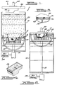
- the inner portion of mask 14 defining aperture 19 is provided with an offset or rabbetted surface 21 allowing seal 18 and a radially extending lip 17 of screen 16 to fit flush to planar surface 15 of mask 14.
- Mask 14 and screen 16 are shown supported by frame member 28 and matrix subframe 30.
- the subframe 30 is a grid of vertically extending metal bars and horizontally extending cross members.
- the top portion of matrix subframe 30 is suitably contoured to substantially match the contoured shape of screen 16 and thereby provide support over the entire surface area of screen 16.
- the bottom portion of subframe 30 is in contact with and suitably connected to frame member 28 thereby receiving support.
- matrix subframe 30 defines a plurality of openings 31 for allowing liquid passing through contoured screen 16 to further pass substantially unobstructed through matrix subframe 30.
- contoured screen 16 is initially positioned at the bottom of tank 12.
- Tank 12 is then filled with water and chopped reinforcing fibers such as glass, graphite, polyester or other suitable reinforcing fibers to create a slurry 35.
- the reinforcing fibers will be in bundles having approximately 500 filaments and a diameter of 2.5 to 25 microns with the bundles cut into one half to six inch lengths.
- binding fibers 50 are added to slurry 35.
- the binding fibers comprise approximately about 3-10 and, preferably, 6 percent by weight of the total weight of the fibers added to create slurry 35.
- the binding fiber 50 of the present invention is shown in Figure 8 as a combination 52 of thermoplastic material having therein dispersed a quantity of filler material 54 having ferromagnetic properties.
- the combination material 52 may be any of the thermoplastic materials, such as thermoplastic polyester, polypropylene, polyethylene, or nylon, suitable for forming into fibers.
- the filler material may be any ferromagnetic material which may be made into small particles to be dispersed into the thermoplastic matrix.
- suitable ferromagnetic materials are discussed in U.S. Patent No. 2,393,541 (hereby incorporated by reference) and include iron, nickel, cobalt and their respective ferromagnetic alloys and oxides.
- the fiber 50 could consist of a thermoplastic polyester material with a 5-20 percent by weight dispersion of iron oxide particles having an irregular spherical shape approximately about 0.5-5 microns in diameter.
- the filler material 54 produces heat which then melts the thermoplastic material 52 binding the reinforcing fibers of the fiber preform in place.
- the fibers 50 can be made by melting a mass of thermoplastic material, adding thereto a mass of ferromagnetic material, mixing them to create a homogeneous mixture, extruding the mixture through a spinnerette or other suitable device and spinning or drawing it to a predetermined diameter. The fiber may then be cut to length.
- the fiber 50 is preferably 25-50 microns in diameter and cut approximately about 0.25-1.25 inches in length.
- contoured screen 16 mask 14 and frame 28 are raised to the top of tank 12 by activating a piston 31 attached to frame 28.
- a piston 31 attached to frame 28.
- This partial vacuum accompanied with the atmospheric pressure bearing down on the portion of slurry 35 above screen 16 cause the flow of slurry 35 through contoured screen 16 and the dispersion of fibers onto the screen.
- the slurry is prevented from passing between mask 14 and walls of tank 12 by seal 20.
- This pressure differential is equalized when any portion of mask 14 or screen 16 breaks the surface of slurry 35 thereby stopping the flow of slurry 35 through screen 16.
- planar surface 15 of mask 14 is shown extending from the outer walls of tank 12 inwardly to aperture 19.
- planar surface 15 of mask 14 allows for the pressure differential to be maintained for the maximum period of time by substantially maintaining all portions of screen 16 and mask 14 below the surface of slurry 35 until screen 16 reaches the top of tank 12.
- planar surface 15 further advantageously provides a smooth, unobstructed surface over which substantially all of the fibers of slurry 35 may be swept into contoured screen 16.
- Another advantage of mask 14 and planar surface 15 is demonstrated by the provision for mixing the reinforcing fibers.
- a plurality of dispersion tubes 24 connected to the surface of mask 14 by a plurality of apertures 26 formed in mask 14. Air or water or other fluid is advantageously conducted to dispersion tubes 24 from a source 34 through hollow piston rod 31 and suitable connections to conduct fluid from hollow piston rod 31 to dispersion tubes 24. Air provided to tubes 24 is then conducted into tank 12 via apertures 26. In this manner slurry 35 is agitated directly above planar surface 15 thus assuring an even distribution of the reinforcing and binding fibers in slurry 35 and further improving the flow of slurry 35 over planar surface 15 to contoured screen 16.
- Figures 2 and 3 show the first embodiment of the present apparatus in its finished position.
- the reinforcing fibers and binding fibers of slurry 35 are deposited on contoured screen 16 in the desired preformed shape 36.
- High frequency electromagnetic field generator 40 is then lowered into close proximity with fiber preform 36.
- high frequency electromagnetic field generator 40 has a contoured plug 42 of substantially the same shape as preform 36 mounted to a base 45. Embedded near the surface 43 of plug 42 are a plurality of electromagnetic induction coils 44.
- plug 42 when lowered under the action of piston 48, plug 42 slightly compacts the fibers of preform 36 as a high frequency electromagnetic field is generated thereby melting the thermoplastic binding fibers and temporarily binding the reinforcing fibers of preform 36.
- the high frequency electromagnetic field is generated by a suitable control source (not shown) in the range of 2 KHz to 2 MHz with a typical application consisting of 1 MHz field active for approximately about 2-15, and preferably about 5 seconds.
- the heating of the binding fibers 50 by the electromagnetic field raises the temperature in the immediate area to cause localized vaporization of any water droplets adjacent to the binding fibers.
- the heat of the binding fibers during application of the electromagnetic field, may cause water droplets to be driven away from the hot binding fibers thereby allowing the binding fibers to melt and act as an adhesive to bind together adjacent reinforcing fibers.
- the electromagnetic field When the electromagnetic field is removed, the water droplets in the vicinity tend to return to their original location due to capillary action thereby quenching the hot binding fibers to cool and solidify them. Accordingly, the electromagnetic field need be applied only for a limited period of time in order to transform the wet, unmanageable raw preform into an easily handled unit.
- preform 36 may be removed from contoured screen 16 by any suitable method.
- An exemplary preform made in accordance with the teachings of this embodiment of the present invention is illustrated in Figure 4.
- contoured screen 16 would be suitably coated with Teflon® or other anti-sticking compound so as to prevent sticking of preform 36 to contoured screen 16 thereby improving the removal process.
- the removed preform then can be subjected to a drying process to remove residual water from the preform. This can be accomplished in a variety of manners such as forced air convection drying and other suitable methods which would be compatible with the teachings of the present invention.
- a fiber reinforced part is created by placing the preform in a mold and injecting resin into the mold. The resin impregnates the fibers of the preform thereby forming the desired structure.
- FIGS. 9-12 show a second embodiment of the present invention. Like reference numerals are used to identify like elements of the preceding embodiment.
- contoured screen 16 is initially positioned at the bottom of tank 12.
- Tank 12 is then filled with water and chopped reinforcing fibers to create a slurry 35.
- the binding fibers are just a matrix of thermoplastic material, and preferably, thermoplastic fibers.
- the matrix material may be any of the thermoplastic materials, such as thermoplastic polyester, polypropylene, polyethylene, or nylon, suitable for forming into fibers.
- the binding material consists of a thermoplastic polyester material, which melts when exposed to high temperature steam. When exposed to cool air, the melted thermoplastic fibers solidify to temporarily bind the reinforcing fibers of the fiber reinforced preform in place.
- thermoplastic fibers can be made by melting a mass of thermoplastic material, extruding it through a spinnerette or other suitable device and spinning or drawing it to a predetermined diameter. The fibers may then be cut to length. In the preferred embodiment of the present invention, the fibers are preferably 25-50 microns in diameter and cut approximately about 0.25-1.25 inches in length.
- removable contoured screen 16, mask 14 and frame 28 are raised to the top of tank 12 by activating a piston 31 attached to frame 28 in a similar manner as described in the prior embodiment.
- Figures 10 and 11 show the apparatus in its finished position.
- the reinforcing fibers and binding material of slurry 35 are deposited on removable contoured screen 16 in the desired preformed shape 36.
- a second contoured screen 66 substantially the same shape and size as the inside surface of preform 36 is mounted to base 45.
- Second screen 66 and base 45 are lowered under the action of piston 48.
- Second screen 66 nests within removable contoured screen 16 capturing and holding the reinforcing fibers and binding material in place.
- Second screen 66 and removable contoured screen 16 are forced together with sufficient pressure to compress the reinforcing fibers and binding material together and remove trapped water from the preform.
- high temperature steam inlet conduit 68 and cool air inlet conduit 70 are mounted to base 45.
- Base 45 contains a high temperature steam inlet conduit opening 72 therein to allow for passage of high temperature steam from high temperature steam conduit 68 to chamber 76 and to the inner surface of second screen 66. The high temperature steam is then discharged through a plurality of openings 78 formed in second screen 66 and through preform 36 formed on removable contoured screen 16.
- Base 45 also contains a cool air inlet conduit opening 74 therein to allow for passage of cool air from cool air inlet conduit 70 through base 45 to preform 36 in substantially the same manner.
- removable contoured screen 16, reinforcing fibers, binding material and second screen 66 are exposed to high temperature steam or other heated fluid.
- This high temperature steam is sufficiently hot (at least 150°C) and is maintained for a sufficient period of time (between 15 to 90 seconds) to melt the binding material.
- the heating of the binding material by the high temperature steam raises the temperature of the preform in the immediate area of the binding material causing vaporization of water droplets adjacent to the binding material.
- removable contoured screen 16, reinforcing fibers, binding material and second screen 66 are exposed to a quantity of cool air (below about 150°C) for about 10 to 30 seconds, sufficient enough to solidify the binding material and temporarily lock the reinforcing fibers in place. Accordingly, this high temperature steam and cool air combination need be applied only for a limited period of time in order to transform the wet, unmanageable raw preform into an easily handled unit.
- second screen 66 is retracted to a position above tank 12.
- Removable contoured screen 16, mask 14 and frame 28 are then lowered into tank 12 whereby air in tank 12 trapped between the surface of the slurry and the bottom of mask 14 is forced through removable contoured screen 16 thereby causing preform 36 to be ejected from removable contoured screen 16.
- Ejected preform 36 may be retrieved by any suitable method. Retrieved preform 36 then can be subjected to a drying process to remove residual water. This can be accomplished in a variety of manners such as forced air convection drying and other suitable methods which would be compatible with the teachings of the present invention.
- a fiber reinforced part is created by placing preform 36 in a mold and injecting resin into the mold, preferably using the above-described resin transfer molding (RTM) process.
- RTM resin transfer molding
- Figures 13-17 show a third embodiment of the present invention where, unlike the previous embodiments, there is no need for the resin injection step to form the final part.
- Like reference numerals are used to identify like elements of the preceding embodiments.
- FIG. 13 A schematic representation, as shown in Figure 13, concisely and succinctly sets forth the steps for forming a fiber reinforced plastic structure according to the third embodiment of the present invention.
- contoured screen 16 is initially positioned at the bottom of tank 12.
- Tank 12 is then filled with water and chopped reinforcing fibers 81 to create a slurry 35.
- binding fibers 83 of the type generally disclosed in the earlier embodiments are added to slurry 35 along with resin matrix fibers 85.
- the binding fibers 83 are made of thermoplastic material and have a lower melting point and a lower proportion by weight when compared with the resin matrix fibers 85.
- the binding fibers 83 comprise approximately 2-7 percent by weight of the total weight of the preform and have a melting temperature of less than about 270°F.
- thermoplastic resin matrix fibers 85 comprise approximately 30-70 percent by weight of the total weight of the preform and have a melting temperature of between about 300°F and about 450°F.
- the reinforcing fibers 81 constitute the balance of the total weight of the fiber reinforced plastic structure.
- the reinforcing fibers 81 may be made from glass, graphite, polyester or other suitable reinforcing fibers. Typically, the reinforcing fibers 81 will be approximately 0.5 to 4 inches in length and 25 to 50 microns in diameter.
- the binding fibers 83 are about 25 to 50 microns in diameter and about 0.25 to 1.25 inches in length.
- the binding fibers 83 can be made of thermoplastic polyester, polypropylene, polyethylene or nylon.
- the thermoplastic resin matrix fibers 85 can be made of polypropylene, thermoplastic polyesters (PETs) or nylons, with a length of about 0.5 to 3 inches and a diameter of about 25 to 50 microns.
- PETs thermoplastic polyesters
- the reinforcing fibers 81, the binding fibers 83 and the matrix resin fibers 85 of slurry 35 are uniformly deposited on removable contoured screen 16 in the desired preform 36 shape.
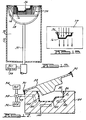
- the contoured screen 16 and wet preform 36 are removed from tank 12 and placed into an oven 79 as shown at box 204 of Figure 13 and schematically illustrated in Figure 16.
- High temperature fluid such as steam, is then drawn through preform 36 by creating a negative pressure differential between the top and bottom of preform 36. The high temperature fluid or steam generated thereby will be sufficient to melt the thermoplastic binding fibers 83 but not the thermoplastic resin matrix fibers 85.
- the preform can remain in the oven which is heated to about 300°F for about 1 minute. After cooling, reinforcing fibers 81 are temporarily bound by the melted binding fibers 83 to create tackified preform 80.
- tackified preform it is meant that the preform is bound together sufficiently so that it can be removed from the screen and handled without being easily deformed. However, it does not have the desired structural rigidity for the final part.
- the tackified preform can generally withstand loads of about 20 psi without substantial deformation but will be deformed by higher loads.
- tackified preform 80 is removed from contoured screen 16 and placed in a complementary cavity 82 of mold 84.
- Mold 84 has a relatively smooth molding surface 86.
- Mold 84 can be open-ended but preferably includes a cover 88.
- Cover 88 can take a variety of forms and it is presently contemplated that it can take the form of a flexible diaphragm which can be drawn by a vacuum against the upper surface of the preform. In Figure 17, however, cover 88 is shown as a pivoted rigid lid having a lower surface complementary in shape to the preform. Cover 88 is attached to mold 84 by any standard type of hinge mechanism 90 and is secured in a closed position by any standard type of latch mechanism 92.
- Cover 88 is held against the outer surface of tackified preform 80 while tackified preform 80 is supported in complementary cavity 82 of mold 84.
- the resultant pressure on tackified preform 80 due to cover 88 is relatively low, however, just sufficient enough to provide part definition.
- high temperature fluid or steam source 94 and cool air source 96 are regulated by valve 98.
- Inlet conduit 99 connects valve 98 to mold 84.
- Heat transfer passageways 100 Disposed within mold 84 are heat transfer passageways 100 which allow for passage of high temperature fluid or steam from source 94 or cool air from source 96 throughout mold 84.
- Heat transfer passageways 100 are oriented in any standard type pattern to sufficiently heat or cool mold 84.
- One skilled in the art would readily recognize that heat transfer passageways 100 can be arranged such that different locations of mold 84 could have different heat transfer rates.
- the mold 84 is heated to a temperature exceeding the melting temperature of the thermoplastic resin matrix fibers 85 to cause them to flow throughout the preform and surround the reinforcing fibers 81.
- the mold is heated to about 300 to 450°F for a period of time between about 30 and 120 seconds.
- cool source 96 provides a sufficient amount of cool air or other fluid through valve 98, inlet conduit 99 and heat transfer passageways 100 to cool the mold 84.
- Tackified preform 80 is thereby cooled, sufficient enough to solidify the melted fibers 85 and bind the reinforcing fibers 81 in place to generate a substantially homogeneous fiber reinforced plastic structure having a sufficient concentration of resin matrix fibers and reinforcing fibers to provide structural rigidity.
- the mold is cooled to below about 290°F for a period of time between about 15 and 30 seconds.
- the final part is then removed from the mold 84.
- the final part is characterized by a significantly higher structural rigidity than the tackified preform. For example, the final part can withstand tensile loads of over 5,000 psi without substantial deformation.
- Some advantages of the method and apparatus of the third embodiment of the present invention is that there is no substantial displacement of fibers as compared to conventional structural molding compound (SMC) compression molding techniques since the slurry process already forces the fibers to be uniformly distributed throughout the preform. Therefore, a better, smoother surface is obtainable since no knit lines are encountered. Additionally, large, high tonnage presses are not required to form the desired fiber reinforced plastic structure. It is also possible thereafter to reheat and reshape the thermoplastic products of the present invention. Moreover, there is no styrene or resin involved in the method of the present invention and, therefore, it is possible to recycle the thermoplastic products generated by this method easier, thereby rendering an increased benefit to the environment.
- SMC structural molding compound
- Another significant advantage is that there is no resin injection step required in order to form the final part, as in the RTM procedure described in connection with the first two embodiments.
Landscapes
- Engineering & Computer Science (AREA)
- Mechanical Engineering (AREA)
- Chemical & Material Sciences (AREA)
- Composite Materials (AREA)
- Manufacturing & Machinery (AREA)
- Textile Engineering (AREA)
- Reinforced Plastic Materials (AREA)
- Moulding By Coating Moulds (AREA)
Applications Claiming Priority (2)
| Application Number | Priority Date | Filing Date | Title |
|---|---|---|---|
| US44341995A | 1995-05-18 | 1995-05-18 | |
| US443419 | 1995-05-18 |
Publications (3)
| Publication Number | Publication Date |
|---|---|
| EP0743165A2 true EP0743165A2 (de) | 1996-11-20 |
| EP0743165A3 EP0743165A3 (de) | 1997-03-19 |
| EP0743165B1 EP0743165B1 (de) | 2000-09-20 |
Family
ID=23760736
Family Applications (1)
| Application Number | Title | Priority Date | Filing Date |
|---|---|---|---|
| EP96303489A Expired - Lifetime EP0743165B1 (de) | 1995-05-18 | 1996-05-16 | Verfahren und Vorrichtung zum Formen verstärkter thermoplastischer Verbundwerkstoffe |
Country Status (5)
| Country | Link |
|---|---|
| EP (1) | EP0743165B1 (de) |
| BR (1) | BR9602341A (de) |
| CA (1) | CA2176416C (de) |
| DE (1) | DE69610357T2 (de) |
| ES (1) | ES2151637T3 (de) |
Cited By (6)
| Publication number | Priority date | Publication date | Assignee | Title |
|---|---|---|---|---|
| FR2864094A1 (fr) * | 2003-12-19 | 2005-06-24 | Rhodia Industrial Yarns Ag | Materiaux composites comprenant un materiau de renfort et une matrice thermoplastique, article compose precurseur de ces materiaux et produits obtenus a partir de ces materiaux |
| EP1777063A1 (de) * | 2005-10-21 | 2007-04-25 | Snecma | Herstellungsverfahren einer Turbinenschaufel aus Verbundwerkstoff und die so erhaltene Schaufel |
| EP1908574A1 (de) * | 2006-10-05 | 2008-04-09 | Novameer B.V. | Verfahren zur Herstellung dreidimensionaler Produkte aus selbstverstärktem Kunststoff |
| EP2752285A4 (de) * | 2011-08-29 | 2015-01-14 | Teijin Ltd | Herstellungsverfahren für einen verbundformkörper mit unterschnittenem querschnitt |
| EP3444105A1 (de) * | 2017-08-14 | 2019-02-20 | The Boeing Company | Hybrides nichtgewebtes verbundteil |
| EP4122685A1 (de) * | 2021-07-23 | 2023-01-25 | Corebon AB | Formwerkzeug, verfahren zur herstellung davon und verfahren zur herstellung eines verbundteils in besagtem werkzeug |
Families Citing this family (1)
| Publication number | Priority date | Publication date | Assignee | Title |
|---|---|---|---|---|
| DE10161773A1 (de) * | 2001-12-15 | 2003-06-26 | Bayerische Motoren Werke Ag | Verfahren zur Herstellung eines dreidimensional geformten Faserverbundkunststoffbauteils |
Family Cites Families (4)
| Publication number | Priority date | Publication date | Assignee | Title |
|---|---|---|---|---|
| DE3113930A1 (de) * | 1981-04-07 | 1982-10-28 | Messerschmitt-Bölkow-Blohm GmbH, 8000 München | Verfahren zur herstellung von gelegen fuer thermoplastische verbundwerkstoffe mit ausgerichteten verstaerkungsfasern |
| DE3636864A1 (de) * | 1986-04-12 | 1987-10-15 | Ebers & Mueller Fibrit | Verfahren zur herstellung eines vorformlings aus faserverstaerktem material |
| DE3614533A1 (de) * | 1986-04-29 | 1987-11-05 | Walter Isphording | Verfahren zum herstellen von kompakten, eine verstaerkungseinlage aus fasern enthaltenden formkoerpern aus thermoplastischem kunststoff |
| US5286326A (en) * | 1992-05-12 | 1994-02-15 | The Budd Company | Method for binding fibers in a fiber reinforced preform using an electromagnetic field to melt binding fibers |
-
1996
- 1996-05-13 CA CA002176416A patent/CA2176416C/en not_active Expired - Fee Related
- 1996-05-16 ES ES96303489T patent/ES2151637T3/es not_active Expired - Lifetime
- 1996-05-16 DE DE69610357T patent/DE69610357T2/de not_active Expired - Fee Related
- 1996-05-16 EP EP96303489A patent/EP0743165B1/de not_active Expired - Lifetime
- 1996-05-17 BR BR9602341A patent/BR9602341A/pt active Search and Examination
Cited By (13)
| Publication number | Priority date | Publication date | Assignee | Title |
|---|---|---|---|---|
| FR2864094A1 (fr) * | 2003-12-19 | 2005-06-24 | Rhodia Industrial Yarns Ag | Materiaux composites comprenant un materiau de renfort et une matrice thermoplastique, article compose precurseur de ces materiaux et produits obtenus a partir de ces materiaux |
| WO2005061209A1 (fr) * | 2003-12-19 | 2005-07-07 | Rhodia Industrial Yarns Ag | Matériaux composites comprenant un matériau de renfort et une matrice thermoplastique, article composé precurseur de ces matériaux et produits obtenus a partir de ces matériaux. |
| US9200124B2 (en) | 2003-12-19 | 2015-12-01 | Rhodia Operations | Composite materials comprising a reinforcing material and a thermoplastic matrix, precursor compound article of said materials and products obtained using same |
| US7581932B2 (en) | 2005-10-21 | 2009-09-01 | Snecma | Method of manufacturing a composite turbomachine blade, and a blade obtained by the method |
| FR2892339A1 (fr) * | 2005-10-21 | 2007-04-27 | Snecma Sa | Procede de fabrication d'une aube de turbomachine composite, et aube obtenue par ce procede |
| EP1777063A1 (de) * | 2005-10-21 | 2007-04-25 | Snecma | Herstellungsverfahren einer Turbinenschaufel aus Verbundwerkstoff und die so erhaltene Schaufel |
| EP1908574A1 (de) * | 2006-10-05 | 2008-04-09 | Novameer B.V. | Verfahren zur Herstellung dreidimensionaler Produkte aus selbstverstärktem Kunststoff |
| WO2008040509A3 (en) * | 2006-10-05 | 2008-05-22 | Novameer Bv | Method for producing self-reinforced polymeric three-dimensional products |
| EP2752285A4 (de) * | 2011-08-29 | 2015-01-14 | Teijin Ltd | Herstellungsverfahren für einen verbundformkörper mit unterschnittenem querschnitt |
| EP3444105A1 (de) * | 2017-08-14 | 2019-02-20 | The Boeing Company | Hybrides nichtgewebtes verbundteil |
| US10773468B2 (en) | 2017-08-14 | 2020-09-15 | The Boeing Company | Hybrid non-woven composite part |
| EP4122685A1 (de) * | 2021-07-23 | 2023-01-25 | Corebon AB | Formwerkzeug, verfahren zur herstellung davon und verfahren zur herstellung eines verbundteils in besagtem werkzeug |
| WO2023001577A1 (en) * | 2021-07-23 | 2023-01-26 | Corebon Ab | Molding tool, method of manufacturing the same and method of producing a composite part in said tool |
Also Published As
| Publication number | Publication date |
|---|---|
| EP0743165A3 (de) | 1997-03-19 |
| DE69610357D1 (de) | 2000-10-26 |
| BR9602341A (pt) | 1998-09-01 |
| CA2176416A1 (en) | 1996-11-19 |
| DE69610357T2 (de) | 2001-02-22 |
| EP0743165B1 (de) | 2000-09-20 |
| ES2151637T3 (es) | 2001-01-01 |
| CA2176416C (en) | 1999-07-06 |
Similar Documents
| Publication | Publication Date | Title |
|---|---|---|
| US5286326A (en) | Method for binding fibers in a fiber reinforced preform using an electromagnetic field to melt binding fibers | |
| US5039465A (en) | Method and apparatus for forming fiber reinforced plastic preforms from a wet slurry | |
| US5820801A (en) | Reinforced thermoplastic molding technique method | |
| EP1631441B1 (de) | Verfahren und vorrichtung zur herstellung von dreidimensional ausgeprägten formteilen sowie formteil | |
| US3975479A (en) | Method of fabricating a reinforced plastic article | |
| DE602004009971T2 (de) | Verfahren zur Herstellung einer Sandgiessform | |
| CA1299329C (en) | Semifinished product and process and apparatus for producing a dimensionally stable thermoplastic semifinished product | |
| CA1326749C (en) | Process for the high-speed production of fiber-reinforced plastics | |
| CN85100805A (zh) | 对纤维加固模压塑料物品的改进 | |
| EP0743165B1 (de) | Verfahren und Vorrichtung zum Formen verstärkter thermoplastischer Verbundwerkstoffe | |
| KR100632164B1 (ko) | 섬유-강화 열가소성 수지 성형제품을 제조하기 위한 방법및 그 방법에 의해 제조된 성형제품 | |
| JP2023033471A (ja) | 繊維強化樹脂製品の製造方法およびコア | |
| CA1244211A (en) | Fibre reinforced moulded plastics articles | |
| US5685956A (en) | Method and apparatus for binding fibers in a fiber reinforced preform | |
| CN101420651A (zh) | 喇叭鼓纸的制造方法 | |
| CN108025512B (zh) | 三维高强度纤维复合材料组件及其制造方法 | |
| KR850001249B1 (ko) | 섬유 보강 열 경화성 수지의 제조장치 | |
| CA1124979A (en) | Method of and apparatus for producing shaped bodies of reinforced synthetic resin | |
| DE102012010469B4 (de) | Verfahren zur Herstellung von faserverstärkten Bauteilen | |
| US5376327A (en) | Method and apparatus for hermetic pneumatic rapid preforming of chopped fibers | |
| DE69504987T2 (de) | Verfahren zum formen von faseraggregaten | |
| JPH1034756A (ja) | Frp成形方法および装置 | |
| CA2137169C (en) | Method and apparatus for binding fibers in a fiber reinforced preform | |
| US5814256A (en) | Process of producing preforms containing light weight filler particles | |
| DE3717609A1 (de) | Saugformverfahren zum herstellen von gegenstaenden aus thermoplastischen, stark verunreinigten recycling-kunststoffen |
Legal Events
| Date | Code | Title | Description |
|---|---|---|---|
| PUAI | Public reference made under article 153(3) epc to a published international application that has entered the european phase |
Free format text: ORIGINAL CODE: 0009012 |
|
| AK | Designated contracting states |
Kind code of ref document: A2 Designated state(s): DE ES FR IT NL |
|
| PUAL | Search report despatched |
Free format text: ORIGINAL CODE: 0009013 |
|
| AK | Designated contracting states |
Kind code of ref document: A3 Designated state(s): DE ES FR IT NL |
|
| 17P | Request for examination filed |
Effective date: 19970724 |
|
| 17Q | First examination report despatched |
Effective date: 19980526 |
|
| GRAG | Despatch of communication of intention to grant |
Free format text: ORIGINAL CODE: EPIDOS AGRA |
|
| GRAG | Despatch of communication of intention to grant |
Free format text: ORIGINAL CODE: EPIDOS AGRA |
|
| GRAH | Despatch of communication of intention to grant a patent |
Free format text: ORIGINAL CODE: EPIDOS IGRA |
|
| GRAH | Despatch of communication of intention to grant a patent |
Free format text: ORIGINAL CODE: EPIDOS IGRA |
|
| GRAA | (expected) grant |
Free format text: ORIGINAL CODE: 0009210 |
|
| AK | Designated contracting states |
Kind code of ref document: B1 Designated state(s): DE ES FR IT NL |
|
| REF | Corresponds to: |
Ref document number: 69610357 Country of ref document: DE Date of ref document: 20001026 |
|
| ET | Fr: translation filed | ||
| ITF | It: translation for a ep patent filed | ||
| REG | Reference to a national code |
Ref country code: ES Ref legal event code: FG2A Ref document number: 2151637 Country of ref document: ES Kind code of ref document: T3 |
|
| PGFP | Annual fee paid to national office [announced via postgrant information from national office to epo] |
Ref country code: FR Payment date: 20010501 Year of fee payment: 6 |
|
| PGFP | Annual fee paid to national office [announced via postgrant information from national office to epo] |
Ref country code: DE Payment date: 20010508 Year of fee payment: 6 |
|
| PGFP | Annual fee paid to national office [announced via postgrant information from national office to epo] |
Ref country code: NL Payment date: 20010509 Year of fee payment: 6 |
|
| PGFP | Annual fee paid to national office [announced via postgrant information from national office to epo] |
Ref country code: ES Payment date: 20010608 Year of fee payment: 6 |
|
| PLBE | No opposition filed within time limit |
Free format text: ORIGINAL CODE: 0009261 |
|
| STAA | Information on the status of an ep patent application or granted ep patent |
Free format text: STATUS: NO OPPOSITION FILED WITHIN TIME LIMIT |
|
| 26N | No opposition filed | ||
| PG25 | Lapsed in a contracting state [announced via postgrant information from national office to epo] |
Ref country code: ES Free format text: LAPSE BECAUSE OF NON-PAYMENT OF DUE FEES Effective date: 20020517 |
|
| PG25 | Lapsed in a contracting state [announced via postgrant information from national office to epo] |
Ref country code: NL Free format text: LAPSE BECAUSE OF NON-PAYMENT OF DUE FEES Effective date: 20021201 |
|
| PG25 | Lapsed in a contracting state [announced via postgrant information from national office to epo] |
Ref country code: DE Free format text: LAPSE BECAUSE OF NON-PAYMENT OF DUE FEES Effective date: 20021203 |
|
| PG25 | Lapsed in a contracting state [announced via postgrant information from national office to epo] |
Ref country code: FR Free format text: LAPSE BECAUSE OF NON-PAYMENT OF DUE FEES Effective date: 20030131 |
|
| NLV4 | Nl: lapsed or anulled due to non-payment of the annual fee |
Effective date: 20021201 |
|
| REG | Reference to a national code |
Ref country code: FR Ref legal event code: ST |
|
| REG | Reference to a national code |
Ref country code: ES Ref legal event code: FD2A Effective date: 20030611 |
|
| PG25 | Lapsed in a contracting state [announced via postgrant information from national office to epo] |
Ref country code: IT Free format text: LAPSE BECAUSE OF NON-PAYMENT OF DUE FEES;WARNING: LAPSES OF ITALIAN PATENTS WITH EFFECTIVE DATE BEFORE 2007 MAY HAVE OCCURRED AT ANY TIME BEFORE 2007. THE CORRECT EFFECTIVE DATE MAY BE DIFFERENT FROM THE ONE RECORDED. Effective date: 20050516 |