EP0743401A2 - Dispositif de capot d'un engin de terrassement - Google Patents
Dispositif de capot d'un engin de terrassement Download PDFInfo
- Publication number
- EP0743401A2 EP0743401A2 EP96303374A EP96303374A EP0743401A2 EP 0743401 A2 EP0743401 A2 EP 0743401A2 EP 96303374 A EP96303374 A EP 96303374A EP 96303374 A EP96303374 A EP 96303374A EP 0743401 A2 EP0743401 A2 EP 0743401A2
- Authority
- EP
- European Patent Office
- Prior art keywords
- bonnet
- upper structure
- working machine
- internal combustion
- combustion engine
- Prior art date
- Legal status (The legal status is an assumption and is not a legal conclusion. Google has not performed a legal analysis and makes no representation as to the accuracy of the status listed.)
- Withdrawn
Links
Images


Classifications
-
- E—FIXED CONSTRUCTIONS
- E02—HYDRAULIC ENGINEERING; FOUNDATIONS; SOIL SHIFTING
- E02F—DREDGING; SOIL-SHIFTING
- E02F9/00—Component parts of dredgers or soil-shifting machines, not restricted to one of the kinds covered by groups E02F3/00 - E02F7/00
- E02F9/08—Superstructures; Supports for superstructures
- E02F9/0858—Arrangement of component parts installed on superstructures not otherwise provided for, e.g. electric components, fenders, air-conditioning units
- E02F9/0891—Lids or bonnets or doors or details thereof
-
- E—FIXED CONSTRUCTIONS
- E02—HYDRAULIC ENGINEERING; FOUNDATIONS; SOIL SHIFTING
- E02F—DREDGING; SOIL-SHIFTING
- E02F3/00—Dredgers; Soil-shifting machines
- E02F3/04—Dredgers; Soil-shifting machines mechanically-driven
- E02F3/28—Dredgers; Soil-shifting machines mechanically-driven with digging tools mounted on a dipper- or bucket-arm, i.e. there is either one arm or a pair of arms, e.g. dippers, buckets
- E02F3/30—Dredgers; Soil-shifting machines mechanically-driven with digging tools mounted on a dipper- or bucket-arm, i.e. there is either one arm or a pair of arms, e.g. dippers, buckets with a dipper-arm pivoted on a cantilever beam, i.e. boom
- E02F3/32—Dredgers; Soil-shifting machines mechanically-driven with digging tools mounted on a dipper- or bucket-arm, i.e. there is either one arm or a pair of arms, e.g. dippers, buckets with a dipper-arm pivoted on a cantilever beam, i.e. boom working downwardly and towards the machine, e.g. with backhoes
- E02F3/325—Backhoes of the miniature type
Definitions
- the present invention relates to a hydraulic working machine such as a hydraulic excavator.
- Hydraulic working machines such as hydraulic excavators are known, which includes a revolving upper structure mounted on a mobile lower structure or undercarriage such that the upper structure is substantially received within a circle having a diameter equal to the width of the undercarriage, and a rear portion of the upper structure does never project from the undercarriage while the upper structure is rotating.
- the hydraulic working machines of the type described are able to achieve a desired operation without difficulty as long as the working site is greater than the width of the undercarriage.
- a driver's cab mounted on the upper structure should preferably be placed outside the object of downsizing.
- the cab occupies a relative large space on the small-sized revolving upper structure, limiting or narrowing an internal space of the upper structure which is available for mounting various components, Consequently, the components mounted in the upper structure are closely arranged with one another.
- an internal combustion engine is mounted in a rear portion of the upper structure, and a seat in the cab is located directly above a portion of the engine and extending right over a rear bonnet.
- a modified small-sized hydraulic working machine which has an openable small window formed in a sidewall of the rear bonnet to provide an access to the internal combustion engine when the maintenance is necessary.
- a hydraulic working machine which comprises: an undercarriage; a revolving upper structure rotatably mounted on the undercarriage and having an internal combustion engine mounted therein; a cab disposed on one side of the revolving upper structure and including a seat; and a first bonnet provided on the revolving upper structure at a position in the rear of the seat and covering both an upper portion and a side portion of the internal combustion engine, the first bonnet being openable in the horizontal direction.
- a second bonnet is disposed adjacent to the first bonnet and covers a portion of the internal combustion engine.
- the second bonnet is preferably arranged to cover both an upper part and a side part of said portion of the internal combustion engine. It is further possible to arrange the second bonnet to cover a cooling fan and a radiator that are provided on the internal combustion engine.
- the hydraulic working machine further includes a third bonnet covering a hydraulic oil tank and a fuel tank for the internal combustion engine that are mounted in the revolving upper structure adjacent to a side which is opposite to said one side.
- the first bonnet which covers an upper portion and a side portion of the internal combustion engine, is openable in the horizontal direction and, hence, it makes no contact or interference with a seat overhanging the first bonnet.
- first bonnet In the case where the first bonnet is used in combination with the second bonnet, it is possible to selectively open the first and second bonnets and hence open the corresponding part of the upper structure according to the need for maintenance.
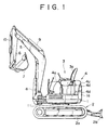
- FIGS. 1 and 2 show a hydraulic working machine according to the present invention which is composed of a small-sized hydraulic excavator designed for use in a limited or narrow working area.
- the small-sized hydraulic excavator includes a revolving upper structure 1 rotatably mounted on a mobile lower structure or undercarriage 2.
- the revolving upper structure 1 has a driver's cab 3 (operating portion) provided on the left side of a front portion of the upper structure 1.
- the revolving upper structure 1 further includes a bonnet assembly 4 so constructed as to surround a right side and a rear side of a lower portion of the cab 3 and contain various apparatus described later on.
- the revolving upper structure 1 further includes a boom 5, an arm 6, and a bucket 7 projecting from the front end of the upper structure 1 in the order named.
- the boom 5, the arm 6 and the bucket 7 are pivotally movable in a vertical plane by means of a boom hydraulic cylinder 8, an arm hydraulic cylinder 9, and a bucket hydraulic cylinder 10, respectively.
- the boom 5 is pivotally mounted on a vertical post 11 disposed on the front end of the revolving upper structure 1 so that the boom 5 can swing or revolve about the vertical post 11 in the leftward and rightward directions of the upper structure 1.
- the undercarriage 2 has a crawler 2a, and a dozer 2b.
- the revolving upper structure 1 has a shape in the plan view which is substantially received within a circle having a diameter equal to the entire width of the machine or vehicle. More particularly, a rear half of the bonnet assembly 4 has a shape completely received within the same circle. Accordingly, the rear half of the bonnet assembly 4 does never project from the overall width of the machine while the upper structure 1 is rotating.
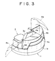
- a counterweight 1a (see FIG. 3) is integrally connected to the rear end of the revolving upper structure 1. The counterweight 1a has a convex shape swelling out from the rear end of the upper structure 1.
- the bonnet assembly 4 of the revolving upper structure 1 has an internal space in which are mounted various apparatus including an internal combustion engine 17, a hydraulic oil tank 18, and a fuel tank 19 for the internal combustion engine 17.
- the internal combustion engine 17 is mounted in the revolving upper structure 1 at a position located rearward of the cab 3.
- the internal combustion engine 17 is arranged transversely of the revolving upper structure 1 with its crankshaft (not shown) aligned with the transverse direction (widthwise or lateral direction) of the revolving upper structure 1.
- the internal combustion engine 17 is provided with a cooling fan 20 and a radiator 21 that are disposed on the right side of the engine 17, and also with a hydraulic pump 22 which is disposed on the left side of the engine 17 and driven by the engine 17.
- the fuel tank 19 and the hydraulic oil tank 18 are mounted in series in the longitudinal direction of the revolving upper structure 1, with the fuel tank 19 located forwards of the hydraulic oil tank 18.
- the bonnet assembly 4 is composed of a third bonnet 4a covering the hydraulic oil tank 18 and the fuel tank 19, a second bonnet 4b disposed adjacent to a rear end of the third bonnet 4a and covering the radiator 21 and the cooling fan 20 of the internal combustion engine 17, and a first bonnet 4c disposed in the rear of the cab 3 and covering the internal combustion engine 17 and the hydraulic pump 22.
- the first bonnet 4c disposed in the rear of the cab 3 can be opened and closed in the horizontal direction by means of a hinge 4d which is disposed at one side of the cab 3 and has a pivot axis arranged vertically.
- a hinge 4d which is disposed at one side of the cab 3 and has a pivot axis arranged vertically.
- the second bonnet 4b disposed in the rear of the hydraulic oil tank 18 and the fuel tank 19 for the internal combustion engine 17 can be opened and closed in the vertical direction by means of a hinge 4e which is disposed on the other side of the cab 3 and has a pivot axis arranged horizontally.
- a hinge 4e which is disposed on the other side of the cab 3 and has a pivot axis arranged horizontally.
- the first bonnet 4c is openable in the horizontal direction by means of the hinge 4d.
- the first bonnet 4c can, therefore, be readily opened and closed without interference with the seat 3a even though the seat 3a in the cab 3 of the illustrated small-sized hydraulic excavator has a seat back overhanging the first bonnet 4c (see FIG. 1).
- the internal combustion engine 17 and the hydraulic pump 22 can be exposed in condition ready to maintain.
- the second bonnet 4b is opened, the cooling fan 20 and the radiator 21 of the internal combustion engine 17 are exposed in condition ready to maintain .
- the first and second bonnets 4b and 4c when they are opened. provide a large space around the counterweight 1a. Accordingly, the maintenance of the components specified above can be achieved with ease.
- the second bonnet 4b and the first bonnet 4c as indicated by phantom lines shown in FIG. 3, have respective lower edges engageable with an upper edge and opposite side edges of the counterweight 1a. Accordingly, when these bonnets 4b, 4c are closed, the above-specified components mounted in the rear portion of the revolving upper structure 1 are concealed by the second and first bonnets 4b, 4c and the counterweight 1a.
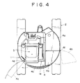
- the second bonnet 4b which is openable in the vertical direction can be modified into a horizontally openable bonnet, such as shown in FIG. 4.
- the horizontally openable second bonnet 4b has a hinge 4f which is disposed on the other side of the seat 3a and has a pivot axis arranged vertically.
- the hydraulic excavator of the embodiments described above has a cab 3 having an exposed seat 3b. It is possible according to another embodiment of the present invention to employ a closed cabin 23 (operating portion) enclosing the seat 3a, as shown in FIG. 5.
- the cabin 23 is profiled such that a rear wall of the cabin 23 overhangs the first bonnet 4c in agreement with the shape of the seat 3a. Since the first bonnet 4c is openable in the horizontal direction (toward the face side on the drawing sheet of FIG. 5), it makes no contract or interference with the cabin 23.
- the internal combustion engine 17 and the hydraulic pump 22 can, therefore, be smoothly placed in the exposed condition which is ready to maintain.
- the first bonnet disposed in the rear of the cab is openable in the horizontal direction, this bonnet can be fully opened with no interference with the seat in the cab. Accordingly, the maintenance of the internal combustion engine and the hydraulic pump can be achieved in the presence of the seat in the cab.
- the second bonnet disposed adjacent to the rear end of the third bonnet is openable either in the horizontal direction or in the vertical direction, the rear portion of the revolving upper structure is opened over a relatively large area when the second and first bonnet are open.
- the second and first bonnets are movable independently from each other and hence can be opened selectively to open the corresponding part of the upper structure according to the need for maintenance. With this arrangement, the maintenance is achievable with improved efficiently.
- the cab may be equipped with a cabin in which instance, however, since the first bonnet has a horizontally openable structure, the rear end portion of the revolving upper structure can be opened in condition ready to maintain without being influenced by the presence of the cabin.
- the counterweight is attached to the rear end of the revolving upper structure at a position laterally spaced from the side edge of the cab and the side edge of the third bonnet, and the second and first bonnets cover the rear end of the revolving upper structure with their lower edges held in contact with an upper edge and opposite side edges of the counterweight. Accordingly, when the second and first bonnets are opened, upper and side boundary areas of the counterweight are widely opened. Under such condition, the maintenance of the components mounted in the rear end portion of the revolving upper structure can be achieved with utmost ease.
Landscapes
- Engineering & Computer Science (AREA)
- Mining & Mineral Resources (AREA)
- Civil Engineering (AREA)
- General Engineering & Computer Science (AREA)
- Structural Engineering (AREA)
- Mechanical Engineering (AREA)
- Component Parts Of Construction Machinery (AREA)
Applications Claiming Priority (2)
| Application Number | Priority Date | Filing Date | Title |
|---|---|---|---|
| JP117454/95 | 1995-05-16 | ||
| JP11745495A JP3572719B2 (ja) | 1995-05-16 | 1995-05-16 | 油圧作業機 |
Publications (2)
| Publication Number | Publication Date |
|---|---|
| EP0743401A2 true EP0743401A2 (fr) | 1996-11-20 |
| EP0743401A3 EP0743401A3 (fr) | 1997-07-23 |
Family
ID=14712067
Family Applications (1)
| Application Number | Title | Priority Date | Filing Date |
|---|---|---|---|
| EP96303374A Withdrawn EP0743401A3 (fr) | 1995-05-16 | 1996-05-14 | Dispositif de capot d'un engin de terrassement |
Country Status (3)
| Country | Link |
|---|---|
| US (1) | US5715615A (fr) |
| EP (1) | EP0743401A3 (fr) |
| JP (1) | JP3572719B2 (fr) |
Cited By (11)
| Publication number | Priority date | Publication date | Assignee | Title |
|---|---|---|---|---|
| FR2772057A1 (fr) * | 1997-12-09 | 1999-06-11 | Kubota Kk | Pelle retrocaveuse |
| EP0879920A3 (fr) * | 1997-05-23 | 1999-07-07 | KABUSHIKI KAISHA KOBE SEIKO SHO also known as Kobe Steel Ltd. | Machine de chantier entraínée par batterie |
| FR2783538A1 (fr) * | 1998-09-22 | 2000-03-24 | Groupe Pel Job | Engin de travaux publics sur lequel est montee une tourelle |
| FR2795108A1 (fr) * | 1999-06-18 | 2000-12-22 | Kubota Kk | Vehicule utilitaire de type pivotant |
| EP1079030A1 (fr) * | 1999-08-26 | 2001-02-28 | Komatsu Ltd | Véhicule de travail |
| EP1254989A4 (fr) * | 2000-01-19 | 2003-07-09 | Yanmar Diesel Engine Co | Cabine de pelle retro |
| EP1493870A1 (fr) * | 2003-07-01 | 2005-01-05 | Kobelco Construction Machinery Co., Ltd. | Engin de travaux |
| EP1306490A4 (fr) * | 2000-05-01 | 2009-04-29 | Yanmar Co Ltd | Engin pivotant |
| CN101550711B (zh) * | 2008-03-31 | 2011-11-16 | 株式会社久保田 | 作业机的上部构造 |
| EP3406804A4 (fr) * | 2016-01-20 | 2019-08-07 | Hitachi Construction Machinery Tierra Co., Ltd. | Engin de construction compact |
| EP3868585A1 (fr) * | 2012-05-28 | 2021-08-25 | Yanmar Power Technology Co., Ltd. | Véhicule de travail rotatif |
Families Citing this family (33)
| Publication number | Priority date | Publication date | Assignee | Title |
|---|---|---|---|---|
| JP3255576B2 (ja) * | 1996-06-28 | 2002-02-12 | コベルコ建機株式会社 | 建設機械のブーム取付装置 |
| JP3310593B2 (ja) * | 1997-09-24 | 2002-08-05 | 株式会社クボタ | バックホウ |
| US6058903A (en) * | 1997-12-18 | 2000-05-09 | Caterpillar Inc. | Engine enclosure |
| JP3533077B2 (ja) * | 1997-12-26 | 2004-05-31 | コベルコ建機株式会社 | 建設機械用ガードカバー |
| DE29804856U1 (de) * | 1998-03-18 | 1998-07-09 | Karl Schaeff GmbH & Co. Maschinenfabrik, 74595 Langenburg | Bagger, insbesondere Minibagger |
| JP4503885B2 (ja) * | 2001-07-09 | 2010-07-14 | ヤンマー株式会社 | 旋回作業車のボンネット |
| US7374208B2 (en) * | 2003-03-18 | 2008-05-20 | Kobelco Construction Machinery Co., Ltd. | Working machine |
| JP4226546B2 (ja) * | 2004-03-29 | 2009-02-18 | 株式会社クボタ | 旋回作業機 |
| JP4226507B2 (ja) * | 2004-03-29 | 2009-02-18 | 株式会社クボタ | 旋回作業機のカバー装置 |
| CN100482901C (zh) * | 2004-03-29 | 2009-04-29 | 株式会社久保田 | 具有旋转台的旋转作业机 |
| JP4619168B2 (ja) * | 2005-03-28 | 2011-01-26 | 株式会社クボタ | 旋回作業機 |
| US7503419B2 (en) * | 2005-09-26 | 2009-03-17 | Kubota Corporation | Backhoe |
| USD559279S1 (en) * | 2006-02-13 | 2008-01-08 | Kobelco Construction Machinery Co., Ltd. | Counterweight for construction machine |
| JP4847974B2 (ja) * | 2008-03-28 | 2011-12-28 | 株式会社クボタ | バックホー |
| JP5185721B2 (ja) * | 2008-07-29 | 2013-04-17 | 日立建機株式会社 | 建設機械 |
| JP5061085B2 (ja) * | 2008-11-17 | 2012-10-31 | 株式会社クボタ | 旋回作業機のボンネットシール構造 |
| US20090313904A1 (en) * | 2009-02-04 | 2009-12-24 | Andrew Kerr | Mechanical access door for passenger bus |
| JP5353795B2 (ja) * | 2010-03-31 | 2013-11-27 | コベルコ建機株式会社 | 作業機械 |
| EP2426277B1 (fr) | 2010-09-06 | 2016-05-11 | Komatsu Ltd. | Section de véhicule avant ou arrière |
| USD678358S1 (en) * | 2012-02-29 | 2013-03-19 | Hitachi Construction Machinery Co., Ltd. | Counterweight for construction machine |
| USD678359S1 (en) * | 2012-03-15 | 2013-03-19 | Hitachi Construction Machinery Co., Ltd. | Counterweight for construction machine |
| USD680136S1 (en) * | 2012-04-24 | 2013-04-16 | Kobelco Construction Machinery Co., Ltd. | Counterweight for construction machine |
| USD684603S1 (en) * | 2012-05-10 | 2013-06-18 | Hitachi Construction Machinery Co., Ltd. | Weight for a construction machine |
| USD684604S1 (en) * | 2012-05-10 | 2013-06-18 | Hitachi Construction Machinery Co., Ltd. | Weight for a construction machine |
| USD684602S1 (en) * | 2012-05-10 | 2013-06-18 | Hitachi Construction Machinery Co., Ltd. | Weight for a construction machine |
| US9211832B1 (en) * | 2012-05-16 | 2015-12-15 | S.A.S. Of Luxemburg, Ltd. | Salvage hold down attachment for excavators |
| JP5923391B2 (ja) * | 2012-06-11 | 2016-05-24 | 株式会社クボタ | 作業機 |
| KR101709094B1 (ko) | 2012-10-25 | 2017-02-22 | 볼보 컨스트럭션 이큅먼트 에이비 | 소선회식 건설기계의 후드 개폐장치 |
| USD693858S1 (en) * | 2012-10-31 | 2013-11-19 | Hitachi Construction Machinery Co., Ltd. | Weight for a construction machine |
| DK178988B1 (en) * | 2015-12-15 | 2017-07-31 | Staal Ind Ivs | Selvkørende universalkøretøj |
| USD954760S1 (en) * | 2019-03-29 | 2022-06-14 | Cnh Industrial America Llc | Ballast for a work vehicle |
| USD954761S1 (en) * | 2019-03-29 | 2022-06-14 | Cnh Industrial America Llc | Rear body assembly for a work vehicle |
| CN113338381B (zh) * | 2021-06-15 | 2023-07-18 | 常州远东工程机械有限公司 | 一种具有回转快速平稳功能的挖掘机配重机构 |
Family Cites Families (18)
| Publication number | Priority date | Publication date | Assignee | Title |
|---|---|---|---|---|
| US3841430A (en) * | 1972-10-02 | 1974-10-15 | Caterpillar Tractor Co | Roll structure cab and seat arrangement for track-type tractors |
| US4062582A (en) * | 1976-05-04 | 1977-12-13 | Fmc Corporation | Truck construction |
| JPS554937U (fr) * | 1978-06-23 | 1980-01-12 | ||
| US4319653A (en) * | 1980-03-24 | 1982-03-16 | Carlson Richard B | Engine enclosure for tractor |
| JPH0410290Y2 (fr) * | 1984-11-28 | 1992-03-13 | ||
| JPH076217B2 (ja) * | 1987-10-09 | 1995-01-30 | 日立建機株式会社 | 全旋回式作業機 |
| DE3834437A1 (de) * | 1988-10-10 | 1990-04-12 | Basf Ag | Azolylmethylcyclopropane und ihre verwendung als pflanzenschutzmittel |
| DE69004287T2 (de) * | 1989-02-16 | 1994-02-24 | Kubota Kk | Hydraulische Rohranordnung für einen Heckbagger. |
| KR920703937A (ko) * | 1989-10-23 | 1992-12-18 | 가타다 테쓰야 | 건설기계의 외장(外裝)장치 |
| JP2810260B2 (ja) * | 1991-10-31 | 1998-10-15 | ヤンマーディーゼル株式会社 | 旋回作業車 |
| US5192108A (en) * | 1992-01-08 | 1993-03-09 | Paccar Inc. | Protective equipment compartment for trucks |
| JPH05311698A (ja) * | 1992-05-15 | 1993-11-22 | Hitachi Constr Mach Co Ltd | 建設機械の作動油タンク装置 |
| JP3190135B2 (ja) * | 1992-09-07 | 2001-07-23 | ヤマハリビングテック株式会社 | 樹脂成形品 |
| DE4232698C1 (de) * | 1992-09-30 | 1993-12-02 | Porsche Ag | Mobilbagger |
| JPH06272279A (ja) * | 1993-03-22 | 1994-09-27 | Kubota Corp | バックホウのボンネット構造 |
| JP2831895B2 (ja) * | 1993-03-23 | 1998-12-02 | 株式会社クボタ | バックホウのボンネット構造 |
| US5481857A (en) * | 1993-09-03 | 1996-01-09 | Kubota Corporation | Mower blade mounting structure |
| JPH07197488A (ja) * | 1993-12-28 | 1995-08-01 | Komatsu Ltd | 油圧ショベルの外装カバー |
-
1995
- 1995-05-16 JP JP11745495A patent/JP3572719B2/ja not_active Expired - Fee Related
-
1996
- 1996-05-14 EP EP96303374A patent/EP0743401A3/fr not_active Withdrawn
- 1996-05-14 US US08/645,758 patent/US5715615A/en not_active Expired - Fee Related
Cited By (16)
| Publication number | Priority date | Publication date | Assignee | Title |
|---|---|---|---|---|
| EP0879920A3 (fr) * | 1997-05-23 | 1999-07-07 | KABUSHIKI KAISHA KOBE SEIKO SHO also known as Kobe Steel Ltd. | Machine de chantier entraínée par batterie |
| FR2772057A1 (fr) * | 1997-12-09 | 1999-06-11 | Kubota Kk | Pelle retrocaveuse |
| FR2783538A1 (fr) * | 1998-09-22 | 2000-03-24 | Groupe Pel Job | Engin de travaux publics sur lequel est montee une tourelle |
| EP0989244A1 (fr) * | 1998-09-22 | 2000-03-29 | Volvo Compact Equipment S.A. | Engin de travaux publics équipé d' une tourelle |
| US6615942B2 (en) | 1999-06-18 | 2003-09-09 | Kubota Corporation | Swivel type working vehicle |
| FR2795108A1 (fr) * | 1999-06-18 | 2000-12-22 | Kubota Kk | Vehicule utilitaire de type pivotant |
| EP1079030A1 (fr) * | 1999-08-26 | 2001-02-28 | Komatsu Ltd | Véhicule de travail |
| US6669272B2 (en) | 2000-01-19 | 2003-12-30 | Yanmar Co., Ltd. | Cabin of back hoe |
| EP1254989A4 (fr) * | 2000-01-19 | 2003-07-09 | Yanmar Diesel Engine Co | Cabine de pelle retro |
| EP1306490A4 (fr) * | 2000-05-01 | 2009-04-29 | Yanmar Co Ltd | Engin pivotant |
| EP1493870A1 (fr) * | 2003-07-01 | 2005-01-05 | Kobelco Construction Machinery Co., Ltd. | Engin de travaux |
| US7134519B2 (en) | 2003-07-01 | 2006-11-14 | Kobelco Construction Machinery Co., Ltd. | Working machine |
| CN101550711B (zh) * | 2008-03-31 | 2011-11-16 | 株式会社久保田 | 作业机的上部构造 |
| EP3868585A1 (fr) * | 2012-05-28 | 2021-08-25 | Yanmar Power Technology Co., Ltd. | Véhicule de travail rotatif |
| EP4450716A3 (fr) * | 2012-05-28 | 2025-01-15 | Yanmar Power Technology Co., Ltd. | Véhicule de travail rotatif |
| EP3406804A4 (fr) * | 2016-01-20 | 2019-08-07 | Hitachi Construction Machinery Tierra Co., Ltd. | Engin de construction compact |
Also Published As
| Publication number | Publication date |
|---|---|
| US5715615A (en) | 1998-02-10 |
| JPH08311926A (ja) | 1996-11-26 |
| JP3572719B2 (ja) | 2004-10-06 |
| EP0743401A3 (fr) | 1997-07-23 |
Similar Documents
| Publication | Publication Date | Title |
|---|---|---|
| US5715615A (en) | Hydraulic working machine | |
| US7320380B2 (en) | Swiveling utility machine having swivel deck | |
| US7481289B2 (en) | Swiveling work machine | |
| KR0182675B1 (ko) | 운전좌석을 상부에 배치하는 보닛을 구비한 포클레인 | |
| JPH0410290Y2 (fr) | ||
| US6155632A (en) | Construction machine | |
| EP1079030B1 (fr) | Véhicule de travail | |
| JP3745510B2 (ja) | 建設機械 | |
| JPH09296481A (ja) | 油圧ショベルにおける上部旋回体の機器取付構造 | |
| JP2000309944A (ja) | 建設機械の工具収容部 | |
| JPH07197488A (ja) | 油圧ショベルの外装カバー | |
| JP3927429B2 (ja) | 旋回型作業機械 | |
| US7243967B2 (en) | Tool storage compartment of a work machine | |
| JP3403633B2 (ja) | 旋回作業機 | |
| JP3393987B2 (ja) | 旋回作業機 | |
| JPH0715891Y2 (ja) | 電動式パワーシヨベルの電動モータ取付装置 | |
| JPH09235752A (ja) | 旋回作業機のボンネット装置 | |
| JP7643375B2 (ja) | 建設機械 | |
| JPH09310375A (ja) | 建設作業機におけるボンネット支持構造 | |
| JP2000096612A (ja) | 旋回作業機並びにこれに用いるキャビン | |
| JPH05311698A (ja) | 建設機械の作動油タンク装置 | |
| JP3547367B2 (ja) | 旋回作業機のボンネット装置 | |
| JPH08218427A (ja) | バックホウ | |
| JP2002327456A (ja) | 建設機械の上部旋回体 | |
| JP3403634B2 (ja) | 旋回作業機 |
Legal Events
| Date | Code | Title | Description |
|---|---|---|---|
| PUAI | Public reference made under article 153(3) epc to a published international application that has entered the european phase |
Free format text: ORIGINAL CODE: 0009012 |
|
| 17P | Request for examination filed |
Effective date: 19960611 |
|
| AK | Designated contracting states |
Kind code of ref document: A2 Designated state(s): DE FR GB IT |
|
| PUAL | Search report despatched |
Free format text: ORIGINAL CODE: 0009013 |
|
| AK | Designated contracting states |
Kind code of ref document: A3 Designated state(s): DE FR GB IT |
|
| 17Q | First examination report despatched |
Effective date: 20001011 |
|
| STAA | Information on the status of an ep patent application or granted ep patent |
Free format text: STATUS: THE APPLICATION IS DEEMED TO BE WITHDRAWN |
|
| 18D | Application deemed to be withdrawn |
Effective date: 20010424 |