EP0743428B1 - Ventilsitzeinsatz - Google Patents
Ventilsitzeinsatz Download PDFInfo
- Publication number
- EP0743428B1 EP0743428B1 EP96107813A EP96107813A EP0743428B1 EP 0743428 B1 EP0743428 B1 EP 0743428B1 EP 96107813 A EP96107813 A EP 96107813A EP 96107813 A EP96107813 A EP 96107813A EP 0743428 B1 EP0743428 B1 EP 0743428B1
- Authority
- EP
- European Patent Office
- Prior art keywords
- valve seat
- seat insert
- based sintered
- added
- cylinder head
- Prior art date
- Legal status (The legal status is an assumption and is not a legal conclusion. Google has not performed a legal analysis and makes no representation as to the accuracy of the status listed.)
- Expired - Lifetime
Links
- 239000000463 material Substances 0.000 claims description 98
- 229910052782 aluminium Inorganic materials 0.000 claims description 32
- 229910052802 copper Inorganic materials 0.000 claims description 26
- 229910052709 silver Inorganic materials 0.000 claims description 22
- 229910052710 silicon Inorganic materials 0.000 claims description 21
- 238000000034 method Methods 0.000 claims description 20
- 229910052718 tin Inorganic materials 0.000 claims description 19
- 229910000838 Al alloy Inorganic materials 0.000 claims description 16
- 229910052725 zinc Inorganic materials 0.000 claims description 16
- 230000003647 oxidation Effects 0.000 claims description 13
- 238000007254 oxidation reaction Methods 0.000 claims description 13
- 229910052742 iron Inorganic materials 0.000 claims description 12
- 229910052759 nickel Inorganic materials 0.000 claims description 12
- 229910018125 Al-Si Inorganic materials 0.000 claims description 11
- 229910018520 Al—Si Inorganic materials 0.000 claims description 11
- 229910017518 Cu Zn Inorganic materials 0.000 claims description 11
- 229910017752 Cu-Zn Inorganic materials 0.000 claims description 11
- 229910017943 Cu—Zn Inorganic materials 0.000 claims description 11
- 238000005266 casting Methods 0.000 claims description 11
- TVZPLCNGKSPOJA-UHFFFAOYSA-N copper zinc Chemical compound [Cu].[Zn] TVZPLCNGKSPOJA-UHFFFAOYSA-N 0.000 claims description 11
- 229910052790 beryllium Inorganic materials 0.000 claims description 8
- 229910052804 chromium Inorganic materials 0.000 claims description 7
- 239000006023 eutectic alloy Substances 0.000 claims description 6
- 229910052796 boron Inorganic materials 0.000 claims description 5
- 238000009713 electroplating Methods 0.000 claims description 5
- 239000011159 matrix material Substances 0.000 claims description 5
- 229910052750 molybdenum Inorganic materials 0.000 claims description 5
- 238000005229 chemical vapour deposition Methods 0.000 claims description 4
- 238000007598 dipping method Methods 0.000 claims description 4
- 238000010285 flame spraying Methods 0.000 claims description 4
- 238000005240 physical vapour deposition Methods 0.000 claims description 4
- 229910052745 lead Inorganic materials 0.000 claims description 3
- 239000000314 lubricant Substances 0.000 claims description 3
- 238000004519 manufacturing process Methods 0.000 claims description 3
- 239000007787 solid Substances 0.000 claims description 3
- 229910052721 tungsten Inorganic materials 0.000 claims description 3
- 229910052720 vanadium Inorganic materials 0.000 claims description 3
- 238000003825 pressing Methods 0.000 claims description 2
- 229910045601 alloy Inorganic materials 0.000 description 19
- 239000000956 alloy Substances 0.000 description 19
- 230000008018 melting Effects 0.000 description 17
- 238000002844 melting Methods 0.000 description 17
- 238000010587 phase diagram Methods 0.000 description 12
- 239000006185 dispersion Substances 0.000 description 9
- 239000007791 liquid phase Substances 0.000 description 9
- 239000012071 phase Substances 0.000 description 9
- 238000009792 diffusion process Methods 0.000 description 5
- 230000005496 eutectics Effects 0.000 description 5
- 239000000203 mixture Substances 0.000 description 5
- 229910018140 Al-Sn Inorganic materials 0.000 description 4
- 229910018137 Al-Zn Inorganic materials 0.000 description 4
- 229910018564 Al—Sn Inorganic materials 0.000 description 4
- 229910018573 Al—Zn Inorganic materials 0.000 description 4
- 229910021364 Al-Si alloy Inorganic materials 0.000 description 3
- 229910018182 Al—Cu Inorganic materials 0.000 description 3
- 238000006243 chemical reaction Methods 0.000 description 3
- 238000001764 infiltration Methods 0.000 description 3
- 230000008595 infiltration Effects 0.000 description 3
- 230000002093 peripheral effect Effects 0.000 description 3
- XAGFODPZIPBFFR-UHFFFAOYSA-N aluminium Chemical compound [Al] XAGFODPZIPBFFR-UHFFFAOYSA-N 0.000 description 2
- 238000002485 combustion reaction Methods 0.000 description 2
- 230000033001 locomotion Effects 0.000 description 2
- 229910000734 martensite Inorganic materials 0.000 description 2
- 239000007790 solid phase Substances 0.000 description 2
- 239000000126 substance Substances 0.000 description 2
- 230000009466 transformation Effects 0.000 description 2
- 229910017982 Ag—Si Inorganic materials 0.000 description 1
- 229910017767 Cu—Al Inorganic materials 0.000 description 1
- 230000002159 abnormal effect Effects 0.000 description 1
- 230000005540 biological transmission Effects 0.000 description 1
- 230000015572 biosynthetic process Effects 0.000 description 1
- 230000001419 dependent effect Effects 0.000 description 1
- 238000000151 deposition Methods 0.000 description 1
- 230000008021 deposition Effects 0.000 description 1
- 230000000694 effects Effects 0.000 description 1
- 238000005470 impregnation Methods 0.000 description 1
- 238000005259 measurement Methods 0.000 description 1
- 239000002923 metal particle Substances 0.000 description 1
- 238000007747 plating Methods 0.000 description 1
- 230000002265 prevention Effects 0.000 description 1
- 238000007789 sealing Methods 0.000 description 1
- 238000003466 welding Methods 0.000 description 1
Images


Classifications
-
- F—MECHANICAL ENGINEERING; LIGHTING; HEATING; WEAPONS; BLASTING
- F01—MACHINES OR ENGINES IN GENERAL; ENGINE PLANTS IN GENERAL; STEAM ENGINES
- F01L—CYCLICALLY OPERATING VALVES FOR MACHINES OR ENGINES
- F01L3/00—Lift-valve, i.e. cut-off apparatus with closure members having at least a component of their opening and closing motion perpendicular to the closing faces; Parts or accessories thereof
- F01L3/22—Valve-seats not provided for in preceding subgroups of this group; Fixing of valve-seats
-
- B—PERFORMING OPERATIONS; TRANSPORTING
- B22—CASTING; POWDER METALLURGY
- B22F—WORKING METALLIC POWDER; MANUFACTURE OF ARTICLES FROM METALLIC POWDER; MAKING METALLIC POWDER; APPARATUS OR DEVICES SPECIALLY ADAPTED FOR METALLIC POWDER
- B22F7/00—Manufacture of composite layers, workpieces, or articles, comprising metallic powder, by sintering the powder, with or without compacting wherein at least one part is obtained by sintering or compression
- B22F7/06—Manufacture of composite layers, workpieces, or articles, comprising metallic powder, by sintering the powder, with or without compacting wherein at least one part is obtained by sintering or compression of composite workpieces or articles from parts, e.g. to form tipped tools
- B22F7/062—Manufacture of composite layers, workpieces, or articles, comprising metallic powder, by sintering the powder, with or without compacting wherein at least one part is obtained by sintering or compression of composite workpieces or articles from parts, e.g. to form tipped tools involving the connection or repairing of preformed parts
-
- C—CHEMISTRY; METALLURGY
- C23—COATING METALLIC MATERIAL; COATING MATERIAL WITH METALLIC MATERIAL; CHEMICAL SURFACE TREATMENT; DIFFUSION TREATMENT OF METALLIC MATERIAL; COATING BY VACUUM EVAPORATION, BY SPUTTERING, BY ION IMPLANTATION OR BY CHEMICAL VAPOUR DEPOSITION, IN GENERAL; INHIBITING CORROSION OF METALLIC MATERIAL OR INCRUSTATION IN GENERAL
- C23C—COATING METALLIC MATERIAL; COATING MATERIAL WITH METALLIC MATERIAL; SURFACE TREATMENT OF METALLIC MATERIAL BY DIFFUSION INTO THE SURFACE, BY CHEMICAL CONVERSION OR SUBSTITUTION; COATING BY VACUUM EVAPORATION, BY SPUTTERING, BY ION IMPLANTATION OR BY CHEMICAL VAPOUR DEPOSITION, IN GENERAL
- C23C26/00—Coating not provided for in groups C23C2/00 - C23C24/00
- C23C26/02—Coating not provided for in groups C23C2/00 - C23C24/00 applying molten material to the substrate
-
- B—PERFORMING OPERATIONS; TRANSPORTING
- B22—CASTING; POWDER METALLURGY
- B22F—WORKING METALLIC POWDER; MANUFACTURE OF ARTICLES FROM METALLIC POWDER; MAKING METALLIC POWDER; APPARATUS OR DEVICES SPECIALLY ADAPTED FOR METALLIC POWDER
- B22F2998/00—Supplementary information concerning processes or compositions relating to powder metallurgy
Definitions
- This invention relates to a valve seat insert having a coated film for a valve seat in a cylinder head made of an aluminum alloy casting and a method for producing a valve seat with a cylinder head made of an aluminum alloy casting.
- valve seat is made with an Fe-based sintered material and bonded around the intake and exhaust ports of the cylinder head by a resistance heat welding process.
- Valve seats made of Fe-based sintered material are for example known from DE-A-4 036 614.
- the Fe-based sintered valve seat material is made by pressing and fusing the metal particles below the melting point, the valve seat is very difficult to be bonded to the cylinder head made of an Al alloy casting. As a result, it is very difficult to provide a bond type of valve seat having a sufficient bond strength.
- valve seat insert as well as a method for producing a valve seat as indicated above which under all running conditions of an engine facilitate an enhanced wear resistance, heat conductivity, and oxidation resistance in dependence of the used materials.
- a valve seat insert as indicated above in that a base material of said valve seat insert is a Fe-based sintered, Cu-based sintered or Ni-based sintered material and that said film consists of Cu, Sn, Zn, Ag, Cu-Zn, Al, Al-Si or Si.
- this objective is solved for a method as indicated above by comprising the steps of (a) placing a valve seat insert onto the surface of a valve opening within said cylinder head, said valve seat insert being made of a Fe-based sintered, Cu-based sintered, or Ni-based sintered material and being provided with a coated film consisting of Cu, Sn, Zn, Ag, Cu-Zn, Al, Al-Si or Si, (b) metallurgically bonding said valve seat insert to said cylinder head, and (c) applying a finishing treatment to said bonded pieces to receive the desired valve seat.
- the film has a thickness of 0.1 ⁇ m to 30 ⁇ m, whereby the material of said film may be capable of forming an eutectic alloy with the material of said cylinder head.
- the base material of said valve seat insert is a Fe-based sintered material
- this Fe-based sintered material comprises a dispersed hard phase containing Fe, Si, or Mo or a deposited carbide complex containing Cr, W, Co, or V and/or an inclusion of solid lubricant consisting of added Cu or impregnated Cu or Pb for an enhanced wear resistance, and added or infiltrated Cu for an enhanced heat conductivity, and added Cr or Ni for an enhanced oxidation resistance.
- the base material of said valve seat insert is a Cu-based sintered material
- said Cu-based sintered material comprises a dispersed hard phase containing Fe, Si, or Mo and/or an increased matrix hardness consisting of added Co, Al, Ni, Si, B, Fe, or Mn, or of added Be, Ti, or Cr for an enhanced wear resistance, and added Al, Be, Ni or Cr for an enhanced oxidation resistance.
- Ni-based sintered material when used for said base material of said valve seat insert, it is advantageous when said Ni-based sintered material comprises a fine oxide film for an enhanced wear resistance, and added Cu for an enhanced heat conductivity.
- Advantageous methods for providing said film are electroplating Cu, Sn, Zn, Ag, or Cu-Zn, or hot dipping into Al, Al-Si, Sn, or Zn, or physical vapour deposition of Cu, Ag, or Si, or chemical vapour deposition of Cu, Ag, or Si, or flame spraying Cu, Sn, Zn, Ag, Al, Al-Si, or Cu-Zn.
- valve seat When a valve seat is bonded to a material to be bonded, made of Al alloy casting, by resistance heat bond process according to this invention, the valve seat is pressed against the material to be bonded and an electric current is applied. Then atom dispersion occurs between a material such as Cu, Sn or the like coated on the valve seat surface (film material) by a process such as plating and a material to be coated, and the material composition near the boundary surface becomes that of an alloy consisting of different elements of both materials. As a result, a stage is brought about in which liquid phase can be produced at a temperature lower than that of each of the pure materials. When temperature rise causes a state in which liquid phase can be produced in the alloy layer, diffusion and melting reaction is further accelerated and the amount of liquid phase increases.
- the liquid phase is discharged to the outside.
- the discharged liquid phase accelerates reaction similar to that described above on the boundary surface yet to react.
- the boundary surface is formed and expanded. A series of reactions are repeated until energization and pressurization are over.
- the valve seat of bonding type is firmly bonded to the material to be bonded.
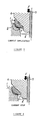
- FIGs. 1 through 6 are half cross sections for explaining the bond process of the bond type valve seat of this invention.
- FIG. 7 is an enlarged drawing of the portion A in FIG. 2.
- FIG. 8 is an enlarged drawing of the portion B in FIG. 3.
- FIG. 9 shows a cross section of the bond type valve seat.
- FIG. 10 shows the relationship between the bond strength of the valve seat and the film thickness thereof.
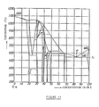
- FIG. 11 is a phase diagram of Al-Cu alloy.
- a cylinder head 1 is made of light-weight aluminum alloy casting.
- a port 2 On the peripheral edge of a port 2 are formed ring-shaped tapered surfaces 2a, 2b, 2c widening upward.
- numeral 3 designates a bond type valve seat of the invention, which is composed of a base material formed with a Fe-based, Cu-based or Ni-based sintered material in a ring shape, and a film 4 (see FIG. 7) 0.1-30 ⁇ m thick and coated on the surface of the base material.
- heat given to the valve is mainly transmitted to the cylinder through the valve seat so that improved heat conductivity of the valve seat helps lower the valve temperature.
- the lowered valve temperature enables prevention of abnormal combustion and improvement in durability of the valve.
- improved heat conductivity of the valve seat causes the temperature fall of the valve seat itself, thereby improving its wear resistance. As a result, high heat conductivity is required for the valve seat.
- Fe-based, Cu-based, and Ni-based sintered materials are selected for the base materials of the bond type valve seat 3 , and measures shown in the following table are taken to provide high wear resistance, heat conductivity and oxidation resistance to these materials.
- Material Function Measure Fe-based sintered material wear resistance ⁇ dispersion of hard phase ⁇ dispersion of hard phase containing Fe, Si, or Mo, or deposition of carbide complex containing Cr, W, Co, or V. ⁇ inclusion of solid lubricant ⁇ addition of Cu, or impregnation of Cu or Pb. heat conductivity addition of Cu, or infiltration of Cu. oxidation resistance addition of Cr or Ni.
- FIG. 9 A detailed cross section of the bond type valve seat 3 is shown in FIG. 9.
- a material for the film 4 is selected so as to produce eutectic alloy between aluminum, which is the main component element of the material of the cylinder head or an Al alloy casting AC2B, AC4B, or AC4C , and an element or a main component element of the selected material, with the melting point of the eutectic alloy being lower than that of aluminum or the element or main component element of the selected material.
- materials shown in Table 3 are selected according to the forming method of the film 4 .
- melting points of Al and Cu are 660°C and 1083°C respectively.
- the temperature T 1 at the eutectic point e is 548°C which is lower than the melting points of Al and Cu 660°C and 1083°C . Therefore, the element Cu which is the material of the film 4 produces, between itself and the main component element Al of the cylinder head 1 , a eutectic alloy having a melting point 548°C lower than the melting points of Al and Cu 660°C and 1083°C .
- a process of bonding the bond type valve seat 3 to the cylinder head 1 will be hereinafter described in reference to FIGs. 1 through 8.
- an outer circumferential projection 3d of the bond type valve seat 3 is brought in contact with a circumferential projection 2d of the port 2 of the cylinder head 1 .
- an electrode 6 of a resistance welder capable of moving up and down along a guide bar 5 is fit into an inner circumferential tapered surface 3a of the bond type valve seat 3 which is pressed by a specified force F against the cylinder head 1 .
- the material of the cylinder head 1 or Al alloy and the material of the film 4 or Cu are brought into contact with each other in solid phase and pressed. This state of contact portions of the valve seat 3 and the cylinder head 1 is shown in FIG. 7.
- the contact portions of the valve seat 3 and the cylinder head 1 begins to melt, and the melting proceeds with the lapse of time so that, as shown in FIG. 8 in detail, the base material of the valve seat 3 or Fe-based sintered material comes into direct contact with the cylinder head 1 .
- Al material of the cylinder head 1 produces a plastic flow in the bond boundary surface between itself and the valve seat 3 to discharge the liquid phase portion produced by the process described above.
- the valve seat 3 is firmly bonded to the peripheral edge of the port 2 disposed in of the cylinder head 1 by the mutual solid phase diffusion of Al and Cu atoms in the contact surface.
- the electrode 6 is removed, and the pressure on the valve seat 3 is removed.
- the valve seat 3 is machined to be finished into a specified shape as shown in FIG. 6.
- the work of bonding the valve seat 3 to the cylinder head 1 is over and the valve seat 3 is firmly bonded to the peripheral edge of the port 2 of the cylinder head 1.
- Fe-based, Cu-based, and Ni-based sintered materials are selected for the base materials of the bond type valve seat 3 , and measures shown in the following table are taken to provide a given electric conductivity, heat conductivity, and high temperature strength.
- Material Function Measure Fe-based sintered material electric conductivity infiltration of Cu. heat conductivity addition of Cu, or infiltration of Cu. hight temperature strength addition of Ni, Co, Mo, V, or Mn. Cu-based sintered material electric conductivity satisfactory because of Cu-base material. heat conductivity satisfactory because of Cu-based material. high temperature strength ⁇ dispersion of hard phase ⁇ dispersion of hard grain containing Fe, Mo ,or Cr.
- Ni-based sintered material electric conductivity addition of Cu. heat conductivity addition of Cu. high temperature strength satisfactory because of Ni-base material.
- elements such as Zn, Sn, Ag, and Si besides Cu can be used as shown in Table 3.
- Phase diagrams for an Al-Zn alloy, Al-Sn alloy, Ag-Al alloy, and Al-Si alloy are shown in FIGs. 12, 13, 14, and 15, respectively.
- melting points of Al and Zn are respectively 660°C and 419°C.
- the temperature T 1 at the eutectic point e of the Al-Zn alloy is 382°C which is lower than the melting points of Al and Zn.
- melting points of Al and Sn are respectively 660°C and 232°C.
- the temperature T 1 at the eutectic point e of the Al-Sn alloy is 228.3°C which is lower than the melting points of Al and Sn.
- melting points of Ag and Al are respectively 950.5°C and 660°C.
- the temperature T 1 at the eutectic point (e) of the Ag-Al alloy is 566°C which is lower than the melting points of Ag and Al.
- melting points of Ag and Si are respectively 660°C and 1430°C.
- the temperature T 1 at the eutectic point (e) of the Al-Si alloy is 577°C which is lower than the melting points of Al and Si.
- Zn, Sn, Ag, and Si or an alloy having those elements as main component elements may be used as the material for the film.
- such methods may be used as; the electroplating, non-electrolytic plating, and flame spraying mentioned before; and further hot dipping, physical vapor deposition, chemical vapor deposition, and application.
Landscapes
- Chemical & Material Sciences (AREA)
- Engineering & Computer Science (AREA)
- Mechanical Engineering (AREA)
- Materials Engineering (AREA)
- Composite Materials (AREA)
- Manufacturing & Machinery (AREA)
- General Engineering & Computer Science (AREA)
- Chemical Kinetics & Catalysis (AREA)
- Metallurgy (AREA)
- Organic Chemistry (AREA)
- Cylinder Crankcases Of Internal Combustion Engines (AREA)
- Powder Metallurgy (AREA)
- Lift Valve (AREA)
Claims (13)
- Ein Ventilsitzeinsatz (3), der einen beschichteten Film (4) für einen Ventilsitz in einem Zylinderkopf (1), hergestellt aus einer Aluminiumgußlegierung, aufweist, wobei ein Grundmaterial des Ventilsitzeinsatzes (3) eine Fe-basierendes, gesintertes, Cu- basierendes, gesintertes oder Ni- basierendes, gesintertes Material ist und daß dieser Film (4) aus Cu, Zn, Ag, Cu-Zn, Al, Al-Si, oder Si besteht.
- Ein Ventilsitzeinsatz (3) nach Anspruch 1, dadurch gekennzeichnet, daß die Dicke des Filmes (4) 0,1 µm bis 30 µm beträgt.
- Ein Ventilsitzeinsatz (3) nach Anspruch 1 oder 2, dadurch gekennzeichnet, daß das Material des Filmes (4) in der Lage ist, mit dem Material des Zylinderkopfes (1) eine eutektische Legierung zu bilden.
- Ein Ventilsitzeinsatz (3) nach zumindest einem der vorhergehenden Ansprüche 1 bis 3, dadurch gekennzeichnet, daß das Grundmaterial ein Fe-basierendes, gesintertes Material ist, mit einer dispergierten harten Phase, enthaltend Fe, Si, oder Mo oder abgeschiedenem Karbidkomplex, enthaltend Cr, W, Co, oder V und /oder einen Einschluß von feste Schmierstoff, bestehend aus zugefügtem Cu oder imprägnierten Cu oder Pb für einen erhöhten Verschleißwiderstand und zugefügtem oder infiltriertem Cu für eine erhöhte Wärmeleitfähigkeit, und zugefügtem Cr oder Ni für einen erhöhten Oxidationswiderstand.
- Ein Ventilsitzeinsatz (3) nach zumindest einem der vorhergehenden Ansprüche 1 bis 3, dadurch gekennzeichnet, daß das Grundmaterial ein Cu-basierendes, gesintertes Material ist, das eine dispergierende harte Phase aufweist, die Fe, Si, oder Mo enthält und/oder eine erhöhte Matrixhärte, bestehend aus zugefügtem Co, Al, Ni, Si, B, Fe, oder Mn, oder zugefügtem Be, Ti, oder Cr für eine erhöhte Verschleißwiderstand aufweist, und zugefügtem Al, Be, Ni oder Cr für einen erhöhten Oxidationswiderstand.
- Ein Ventilsitzeinsatz (3) nach zumindest einem des vorhergehenden Ansprüche 1 bis 3, dadurch gekennzeichnet, daß das Grundmaterial ein Ni-basierendes, gesintertes Material ist, das einen feinen Oxidfilm für einen verbesserten Verschleißwiderstand, und beigefügtes Cu für einen erhöhte Wärmeleitfähigkeit aufweist.
- Ein Ventilsitzeinsatz (3) nach Anspruch 6, dadurch gekennzeichnet, daß das Ni-basierende, gesinterte Material beigefügtes Cu für einen erhöhten Oxidationswiderstand aufweist.
- Ein Ventilsitzeinsatz (3) nach zumindest einem der vorhergehenden Ansprüche 1 bis 7, dadurch gekennzeichnet, daß der Film (4) durch Elektoplattieren von Cu, Sn, Zn, Ag, oder Cu-Zn, oder durch Heißtauchen in Al, Al-Si, Sn, oder Zn, oder durch physikalische Dampfablagerungen von Cu, Ag, oder Si, oder durch chemische Dampfablagerung von Cu, Ag, oder Si, oder durch Flammenspritzen von Cu, Sn, Zn, Ag, Al, Al-Si, oder Cu-Zn, geschaffen wird.
- Ein Ventilsitzeinsatz (3) nach zumindest einem der vorhergehenden Ansprüche 1 bis 4, 7 und 8, dadurch gekennzeichnet, daß das Grundmaterial ein Fe-basierendes, gesintertes Material ist, das infiltriertes Cu für eine gewünschte elektrische Leitfähigkeit aufweist, zugefügtes oder infiltriertes Cu für eine erhöhte Wärmeleitfähigkeit, und zugefügtes Ni, Co, Mo, V, oder Mn für eine erhöhte Hochtemperaturfestigkeit.
- Ein Ventilsitzeinsatz (3) nach zumindest einem der vorhergehenden Ansprüche 1 bis 3, 5,7 und 8, dadurch gekennzeichnet, daß das Grundmaterial ein Cu-basierendes, gesintertes Material ist, mit einer dispergierten harten Phase, die Fe, Mo, oder Cr aufweist, und/oder einer erhöhten Matrixhärte durch zugefügtes Co, Al, Ni, Si, B, Fe, oder Mn oder durch Dispergieren von feinen Ablagerungen durch zugefügtes Be, Ti, oder Cr für eine erhöhte Hochtemperaturfestigkeit.
- Ein Ventilsitzeinsatz (3) nach zumindest einem der vorhergehenden Ansprüche 1 bis 3 und 6 bis 8, dadurch gekennzeichnet, daß das Grundmaterial ein Ni-basierendes gesintertes Material ist, mit zugefügtem Cu für eine gewünschte elektrische Leitfähigkeit sowie eine erhöhte Wärmeleifähigkeit.
- Verfahren zur Herstellung eines Ventilsitzes in einem Zylinderkopf (1), hergestellt aus einer Aluminiumgußlegierung, mit den Schritten:(a) Anordnen eines Ventilsitzeinsatzes (3) auf der Oberfläche einer Ventilöffnung in dem Zylinderkopf (1), wobei der Ventilsitzeinsatz (3) aus Fe-basierendem, gesinterten Material, Cu-basierendem, gesinterten Material oder Ni-basierendem, gesinterten Material hergestellt wird, und mit einer Filmbeschichtung (4) versehen wird, bestehend aus Cu, Sn, Zn, Ag, Cu-Sn, Al, Al-Si oder Si.(b) metallurgisches Haftverbinden des Ventilsitzeinsatzes (3) mit dem Zylinderkopf (1), und(c) Anwendung einer Endbehandlung der haftverbundenen Teile, um den gewünschten Ventilsitz zu erhalten.
- Ein Verfahren nach Anspruch 12, dadurch gekennzeichnet, daß Schritt (b) wie folgt ausgeführt wird:
Pressen des Ventilsitzeinsatzes (3) gegen den Zylinderkopf (1) und anschließend Anlegen einer Spannung zwischen den aneinanderliegenden Oberflächen des Ventilsitzeinsatzes (3) und des Zylinderkopfes (1) bis der Ventilsitzeinsatz (3) und der Zylinderkopf (1) miteinander metallurgisch haftverbunden sind.
Applications Claiming Priority (3)
| Application Number | Priority Date | Filing Date | Title |
|---|---|---|---|
| JP11580995 | 1995-05-15 | ||
| JP115809/95 | 1995-05-15 | ||
| JP7115809A JPH08312800A (ja) | 1995-05-15 | 1995-05-15 | 接合型バルブシート |
Publications (2)
| Publication Number | Publication Date |
|---|---|
| EP0743428A1 EP0743428A1 (de) | 1996-11-20 |
| EP0743428B1 true EP0743428B1 (de) | 2001-03-21 |
Family
ID=14671636
Family Applications (1)
| Application Number | Title | Priority Date | Filing Date |
|---|---|---|---|
| EP96107813A Expired - Lifetime EP0743428B1 (de) | 1995-05-15 | 1996-05-15 | Ventilsitzeinsatz |
Country Status (4)
| Country | Link |
|---|---|
| US (1) | US5692726A (de) |
| EP (1) | EP0743428B1 (de) |
| JP (1) | JPH08312800A (de) |
| DE (1) | DE69612134T2 (de) |
Families Citing this family (20)
| Publication number | Priority date | Publication date | Assignee | Title |
|---|---|---|---|---|
| US5899185A (en) * | 1994-11-25 | 1999-05-04 | Fuji Oozx Inc. | Method of increasing heat transfer of a fitted material of a cylinder head in an internal combustion engine and a fitted portion of the fitted material |
| JP3546261B2 (ja) * | 1996-03-05 | 2004-07-21 | ヤマハ発動機株式会社 | 異種金属材料の接合方法 |
| JPH09317413A (ja) * | 1996-05-28 | 1997-12-09 | Nippon Piston Ring Co Ltd | 接合型バルブシート |
| CA2207579A1 (fr) * | 1997-05-28 | 1998-11-28 | Paul Caron | Piece frittee a surface anti-abrasive et procede pour sa realisation |
| FR2765915B1 (fr) * | 1997-07-10 | 1999-08-27 | Renault | Procede de fabrication d'une culasse a sieges de soupape integres et culasse a sieges de soupape integres |
| DE19912889A1 (de) * | 1999-03-23 | 2000-09-28 | Daimler Chrysler Ag | Verfahren zur Herstellung eines Ventilsitzes |
| DE60010813T2 (de) * | 1999-08-06 | 2004-10-07 | Honda Motor Co Ltd | Diffusionsverbindungsverfahren |
| CA2333933C (en) * | 2000-02-04 | 2004-09-21 | Hitachi, Ltd. | Valve bonded with corrosion and wear proof alloy and apparatuses using said valve |
| DE60105935T2 (de) * | 2000-10-03 | 2005-10-06 | Kabushiki Kaisha Kobe Seiko Sho (Kobe Steel, Ltd.), Kobe | Ventilvorrichtung |
| US20040238780A1 (en) * | 2003-06-02 | 2004-12-02 | Gethmann Doug P. | Control valve with integrated hardened valve seat |
| US7066375B2 (en) * | 2004-04-28 | 2006-06-27 | The Boeing Company | Aluminum coating for the corrosion protection of welds |
| DE102007031464A1 (de) * | 2006-07-17 | 2008-01-24 | Alstom Technology Ltd. | Dampfeinlassventil einer Dampfturbine |
| US8511640B2 (en) * | 2009-12-22 | 2013-08-20 | Hydac Accessories Gmbh | Ball valve with detachable slide bearing bushes |
| WO2013134471A1 (en) * | 2012-03-07 | 2013-09-12 | Waters Technologies Corporation | Low volume, pressure assisted, stem and seat vent valve and associated methods |
| EP2669399B1 (de) * | 2012-06-01 | 2016-10-12 | Oerlikon Metco AG, Wohlen | Lagerteil, sowie thermisches Spritzverfahren |
| JP5990343B2 (ja) * | 2014-08-18 | 2016-09-14 | オリジン電気株式会社 | 金属接合体及び金属接合体の製造方法 |
| CN105351535B (zh) * | 2015-11-11 | 2017-03-22 | 江西鸥迪铜业有限公司 | 一种铝合金家用空调截止阀 |
| JP7090511B2 (ja) * | 2017-09-29 | 2022-06-24 | Dowaエレクトロニクス株式会社 | 銀粉およびその製造方法 |
| DE102018212908B4 (de) * | 2018-08-02 | 2022-09-01 | Ford Global Technologies, Llc | Beschichteter Ventilsitzbereich eines Verbrennungsmotors |
| DE112022000120T5 (de) * | 2021-04-30 | 2023-06-29 | Mitsubishi Heavy Industries, Ltd. | Dampfventil |
Family Cites Families (14)
| Publication number | Priority date | Publication date | Assignee | Title |
|---|---|---|---|---|
| US2753859A (en) * | 1952-03-07 | 1956-07-10 | Thompson Prod Inc | Valve seat insert |
| US4011077A (en) * | 1975-06-06 | 1977-03-08 | Ford Motor Company | Copper coated, iron-carbon eutectic alloy powders |
| US4422875A (en) * | 1980-04-25 | 1983-12-27 | Hitachi Powdered Metals Co., Ltd. | Ferro-sintered alloys |
| JPS58152982A (ja) * | 1982-03-09 | 1983-09-10 | Honda Motor Co Ltd | 高剛性を有する二層焼結合金製バルブシ−トリング |
| IT1155320B (it) * | 1982-04-22 | 1987-01-28 | Fiat Auto Spa | Metodo per l'ottenimento di una sede valvola su una testata di un motore endotermico e motore con sedi valvola ottenute con tale metodo |
| US4546737A (en) * | 1983-07-01 | 1985-10-15 | Sumitomo Electric Industries, Ltd. | Valve-seat insert for internal combustion engines |
| DE3564980D1 (en) * | 1984-06-12 | 1988-10-20 | Sumitomo Electric Industries | Valve-seat insert for internal combustion engines and its production |
| JPS6176742A (ja) * | 1984-09-25 | 1986-04-19 | Toyota Motor Corp | バルブシ−トリングレス軽合金シリンダヘツド |
| JPS62150014A (ja) * | 1985-12-25 | 1987-07-04 | Toyota Motor Corp | アルミニウム合金製バルブシ−トレスシリンダヘツド |
| JPH03158445A (ja) * | 1989-11-16 | 1991-07-08 | Mitsubishi Materials Corp | 耐摩耗性に優れたFe基焼結合金製バルブシート |
| US5260137A (en) * | 1990-06-07 | 1993-11-09 | Avco Corporation | Infiltrated fiber-reinforced metallic and intermetallic alloy matrix composites |
| GB9311051D0 (en) * | 1993-05-28 | 1993-07-14 | Brico Eng | Valve seat insert |
| US5495837A (en) * | 1993-06-11 | 1996-03-05 | Mitsubishi Materials Corporation | Engine valve having improved high-temperature wear resistance |
| JP3328753B2 (ja) * | 1993-12-22 | 2002-09-30 | フジオーゼックス株式会社 | 肉盛用Fe基合金組成物 |
-
1995
- 1995-05-15 JP JP7115809A patent/JPH08312800A/ja active Pending
-
1996
- 1996-05-15 DE DE69612134T patent/DE69612134T2/de not_active Expired - Fee Related
- 1996-05-15 US US08/645,025 patent/US5692726A/en not_active Expired - Fee Related
- 1996-05-15 EP EP96107813A patent/EP0743428B1/de not_active Expired - Lifetime
Also Published As
| Publication number | Publication date |
|---|---|
| DE69612134D1 (de) | 2001-04-26 |
| EP0743428A1 (de) | 1996-11-20 |
| US5692726A (en) | 1997-12-02 |
| JPH08312800A (ja) | 1996-11-26 |
| DE69612134T2 (de) | 2001-07-19 |
Similar Documents
| Publication | Publication Date | Title |
|---|---|---|
| EP0743428B1 (de) | Ventilsitzeinsatz | |
| US6138351A (en) | Method of making a valve seat | |
| JP2923305B2 (ja) | ピストン中の構成部品結合方法 | |
| JP3287916B2 (ja) | バルブシートの接合構造 | |
| EP0723069B1 (de) | Ventil-Sitz für einen Zylinderkopf und Verfahren zu ihrer Herstellung | |
| US5787853A (en) | Valve seat-bonding area structures and valve seat-bonded cylinder head with the structures | |
| CN114016015A (zh) | 滑动构件及其制造方法 | |
| US5954020A (en) | Cup-shaped tappet | |
| JP3546261B2 (ja) | 異種金属材料の接合方法 | |
| US6385847B1 (en) | Seat faced engine valves and method of making seat faced engine valves | |
| US20060162686A1 (en) | Valve seat and method for producing a valve seat | |
| JP6905689B2 (ja) | 摺動部材及び内燃機関の摺動部材 | |
| US6397464B1 (en) | Method for producing a valve seat | |
| US5809644A (en) | Valve lifter | |
| DE102021111283A1 (de) | Ventilsitz für automobil-zylinderkopf | |
| US7401586B2 (en) | Valve seat rings made of basic Co or Co/Mo alloys, and production thereof | |
| EP0843024B1 (de) | Herstellungsverfahren für Ventilstössel einer Brennkraftmaschine | |
| CN110248752B (zh) | 滑动构件和内燃机的滑动构件 | |
| EP0819836B1 (de) | Zylinderkopf und Verfahren zur Herstellung eines Ventilsitzes | |
| JPH0658116A (ja) | バルブシート | |
| JPH09317413A (ja) | 接合型バルブシート | |
| US12595754B2 (en) | Sliding member and internal combustion engine | |
| JPH0480991B2 (de) | ||
| JPH11173113A (ja) | バルブリフタおよびその製造方法 | |
| JPS61166984A (ja) | 耐摩耗性Al合金部材 |
Legal Events
| Date | Code | Title | Description |
|---|---|---|---|
| PUAI | Public reference made under article 153(3) epc to a published international application that has entered the european phase |
Free format text: ORIGINAL CODE: 0009012 |
|
| AK | Designated contracting states |
Kind code of ref document: A1 Designated state(s): DE FR |
|
| 17P | Request for examination filed |
Effective date: 19970411 |
|
| GRAG | Despatch of communication of intention to grant |
Free format text: ORIGINAL CODE: EPIDOS AGRA |
|
| 17Q | First examination report despatched |
Effective date: 20000425 |
|
| GRAG | Despatch of communication of intention to grant |
Free format text: ORIGINAL CODE: EPIDOS AGRA |
|
| GRAH | Despatch of communication of intention to grant a patent |
Free format text: ORIGINAL CODE: EPIDOS IGRA |
|
| GRAH | Despatch of communication of intention to grant a patent |
Free format text: ORIGINAL CODE: EPIDOS IGRA |
|
| GRAA | (expected) grant |
Free format text: ORIGINAL CODE: 0009210 |
|
| AK | Designated contracting states |
Kind code of ref document: B1 Designated state(s): DE FR |
|
| REF | Corresponds to: |
Ref document number: 69612134 Country of ref document: DE Date of ref document: 20010426 |
|
| ET | Fr: translation filed | ||
| PLBE | No opposition filed within time limit |
Free format text: ORIGINAL CODE: 0009261 |
|
| STAA | Information on the status of an ep patent application or granted ep patent |
Free format text: STATUS: NO OPPOSITION FILED WITHIN TIME LIMIT |
|
| 26N | No opposition filed | ||
| PGFP | Annual fee paid to national office [announced via postgrant information from national office to epo] |
Ref country code: DE Payment date: 20080522 Year of fee payment: 13 |
|
| PGFP | Annual fee paid to national office [announced via postgrant information from national office to epo] |
Ref country code: FR Payment date: 20090515 Year of fee payment: 14 |
|
| PG25 | Lapsed in a contracting state [announced via postgrant information from national office to epo] |
Ref country code: DE Free format text: LAPSE BECAUSE OF NON-PAYMENT OF DUE FEES Effective date: 20091201 |
|
| REG | Reference to a national code |
Ref country code: FR Ref legal event code: ST Effective date: 20110131 |
|
| PG25 | Lapsed in a contracting state [announced via postgrant information from national office to epo] |
Ref country code: FR Free format text: LAPSE BECAUSE OF NON-PAYMENT OF DUE FEES Effective date: 20100531 |