EP0743469B1 - Bremszuspannvorrichtung - Google Patents
Bremszuspannvorrichtung Download PDFInfo
- Publication number
- EP0743469B1 EP0743469B1 EP96105532A EP96105532A EP0743469B1 EP 0743469 B1 EP0743469 B1 EP 0743469B1 EP 96105532 A EP96105532 A EP 96105532A EP 96105532 A EP96105532 A EP 96105532A EP 0743469 B1 EP0743469 B1 EP 0743469B1
- Authority
- EP
- European Patent Office
- Prior art keywords
- brake
- piston rod
- actuation
- piston
- brake actuator
- Prior art date
- Legal status (The legal status is an assumption and is not a legal conclusion. Google has not performed a legal analysis and makes no representation as to the accuracy of the status listed.)
- Expired - Lifetime
Links
- 238000010276 construction Methods 0.000 claims description 5
- 238000009434 installation Methods 0.000 claims 1
- 239000012528 membrane Substances 0.000 description 12
- 230000008878 coupling Effects 0.000 description 4
- 238000010168 coupling process Methods 0.000 description 4
- 238000005859 coupling reaction Methods 0.000 description 4
- 238000004519 manufacturing process Methods 0.000 description 4
- 238000005260 corrosion Methods 0.000 description 3
- 230000007797 corrosion Effects 0.000 description 3
- 238000011109 contamination Methods 0.000 description 2
- 238000012423 maintenance Methods 0.000 description 2
- 230000015572 biosynthetic process Effects 0.000 description 1
- 230000001771 impaired effect Effects 0.000 description 1
- 239000002184 metal Substances 0.000 description 1
- 230000000149 penetrating effect Effects 0.000 description 1
- 230000035515 penetration Effects 0.000 description 1
- 230000002093 peripheral effect Effects 0.000 description 1
- 230000000284 resting effect Effects 0.000 description 1
Images


Classifications
-
- F—MECHANICAL ENGINEERING; LIGHTING; HEATING; WEAPONS; BLASTING
- F16—ENGINEERING ELEMENTS AND UNITS; GENERAL MEASURES FOR PRODUCING AND MAINTAINING EFFECTIVE FUNCTIONING OF MACHINES OR INSTALLATIONS; THERMAL INSULATION IN GENERAL
- F16D—COUPLINGS FOR TRANSMITTING ROTATION; CLUTCHES; BRAKES
- F16D65/00—Parts or details
- F16D65/14—Actuating mechanisms for brakes; Means for initiating operation at a predetermined position
- F16D65/16—Actuating mechanisms for brakes; Means for initiating operation at a predetermined position arranged in or on the brake
- F16D65/18—Actuating mechanisms for brakes; Means for initiating operation at a predetermined position arranged in or on the brake adapted for drawing members together, e.g. for disc brakes
-
- B—PERFORMING OPERATIONS; TRANSPORTING
- B60—VEHICLES IN GENERAL
- B60T—VEHICLE BRAKE CONTROL SYSTEMS OR PARTS THEREOF; BRAKE CONTROL SYSTEMS OR PARTS THEREOF, IN GENERAL; ARRANGEMENT OF BRAKING ELEMENTS ON VEHICLES IN GENERAL; PORTABLE DEVICES FOR PREVENTING UNWANTED MOVEMENT OF VEHICLES; VEHICLE MODIFICATIONS TO FACILITATE COOLING OF BRAKES
- B60T17/00—Component parts, details, or accessories of power brake systems not covered by groups B60T8/00, B60T13/00 or B60T15/00, or presenting other characteristic features
- B60T17/08—Brake cylinders other than ultimate actuators
- B60T17/081—Single service brake actuators
-
- F—MECHANICAL ENGINEERING; LIGHTING; HEATING; WEAPONS; BLASTING
- F16—ENGINEERING ELEMENTS AND UNITS; GENERAL MEASURES FOR PRODUCING AND MAINTAINING EFFECTIVE FUNCTIONING OF MACHINES OR INSTALLATIONS; THERMAL INSULATION IN GENERAL
- F16D—COUPLINGS FOR TRANSMITTING ROTATION; CLUTCHES; BRAKES
- F16D2121/00—Type of actuator operation force
- F16D2121/14—Mechanical
-
- F—MECHANICAL ENGINEERING; LIGHTING; HEATING; WEAPONS; BLASTING
- F16—ENGINEERING ELEMENTS AND UNITS; GENERAL MEASURES FOR PRODUCING AND MAINTAINING EFFECTIVE FUNCTIONING OF MACHINES OR INSTALLATIONS; THERMAL INSULATION IN GENERAL
- F16D—COUPLINGS FOR TRANSMITTING ROTATION; CLUTCHES; BRAKES
- F16D2125/00—Components of actuators
- F16D2125/18—Mechanical mechanisms
- F16D2125/20—Mechanical mechanisms converting rotation to linear movement or vice versa
- F16D2125/22—Mechanical mechanisms converting rotation to linear movement or vice versa acting transversely to the axis of rotation
- F16D2125/26—Cranks
Definitions
- the present invention relates to a brake application device according to the Preamble of claim 1.
- Brake application devices of the generic type are used in particular for such Commercial and rail vehicles used, which are equipped with a compressed air brake system are, the exact structure of such brake application devices in numerous Publications are described in more detail.
- DE 42 12 382 A1 which has a brake cylinder Brake application device disclosed that for actuation or for application a disc brake is provided.
- a brake application device with the features of the preamble, in which also the Piston rod is releasably attachable to the piston plate, is from the post-published EP 0 740 085A1 known.
- brake cylinder 200 of such an application device Memb-ran 22 on the one hand on compressed air in a particular, in the Figures with X designated actuation direction is applied so that it is in moving in that direction.
- a piston plate 20 is located on the other side of the membrane 22 at the center of which extends in the direction of actuation of the brake cylinder 200 Approach 21 is provided, with its end facing away from the piston plate in a recess 33 of a piston rod 30 is inserted, which in turn a Brake application element 50 actuated.
- the Membrane 22 of the brake cylinder 200 additionally from a parking brake element (not shown) charged to the in the event of a compressed air failure or for parking To be able to operate the brake as well.
- parking brake elements are mostly as Spring-loaded piston formed, the piston resting in the middle of the membrane so that its axis coincides with that of the piston rod 30.
- the brake application element actuated by the piston rod 30 - or in the case of the aforementioned DE 42 12 382 A1 application device of the rotary lever - describes one of the in the course of its actuation by the piston rod 30 Actual operating direction X deviating, approximately circular segment-shaped path, which deviates relatively strongly from the actuation direction X when the brake is fully actuated. Due to the flexibility of the membrane 22, the safe function of the application device 1 not affected by this in the normal case, since it is the membrane 22 of the piston rod 30 and the piston plate 20 connected to this allows to tilt laterally or to assume an approximately oblique position.
- a generic brake application device is known from FR-A-2 331 717, in which the piston rod of a brake cylinder is articulated on a lever for tensioning the brake is applied.
- the brake cylinder is relatively cumbersome to use Screw arrangement of a brake application device attached. When removing the Brake cylinder is not guaranteed that the brake application by penetrating Dirt is impaired in function.
- the invention has for its object a brake application device according to the Develop the preamble of claim 1 such that the application device in the disassembled state of the brake cylinder through an uncomplicated design Measure is protected against contamination.
- the piston rod is designed so that it is articulated to the rotary lever in the event of a failure, the load on the crossbar Spring reaches that the brake application element in the form of the rotary lever does not disengage with the piston rod.
- the rotary lever is rather the one coupled with it Piston rod under the action of the spring of the brake cylinder always safely in its Starting position brought back.
- An inadequate coupling of the piston rod and brake failure attributable to the rotary lever can therefore be reliably prevented be so that the reliability of the brake application device can be further increased can. Since the coupling according to the invention can also be implemented with little effort can, this security gain with only small or almost negligible Bought additional costs.
- the piston rod so that it can be detachably attached to the piston plate, for example in that a round recess is formed in the piston rod, into which a pin-shaped Approach of the piston plate can be introduced.
- the opening through which the piston rod in the housing of the brake application device immersed in order to apply the brake application element by means of to seal a bellows on the one hand on the circumference of the opening and on the other hand is attached to the end of the piston rod facing away from the brake application element.
- This measure also ensures that the brake cylinder is disassembled prevents any contamination or moisture from getting inside the tensioner penetration.
- the sensitive parts of the application device are thus always reliably protected, so that the risk of brake failure due to corrosion the moving parts of the application device is further reduced.
- a particular advantage of the construction according to the invention is that that the piston rod is directly and immediately detachably attached to the piston plate, the actual construction of the brake application device and the brake cylinder is not unnecessary is complicated.
- EP 0 012 024 is also a multi-part design of the piston rod of the brake cylinder with a Avoid section on the brake cylinder and a section in the application device.
- the piston rod can be releasably attached to the brake application element. If - like this in practice is often the case - the piston rod is hemispherical at its end and to form a ball socket joint into a corresponding hemispherical Recess of the brake application element engages such a releasable articulated Connection can be formed in a simple and inexpensive manner in that the piston rod is attached to the brake application element by means of a clamping bracket; around To compensate for manufacturing tolerances, this clamp is preferably a spring clip.
- Such a clamp is preferably attached to the piston rod or pin-shaped projections are formed on the brake application element, in which the clamp is pivoted while in the other part (i.e. in the brake application element or in the piston rod) one preferably rotating trained recess is provided, in which a designed as a clamping element Part of the clamp can snap into place. Both assembly and disassembly can thus be carried out with the simplest of means.
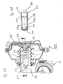
- FIG. 1 shows an application device 1 according to the invention shown, in a state in which an associated Brake cylinder 200 is disassembled from it.
- Fig.1 points the brake cylinder 200 a lower or left chamber 27 and an upper or right chamber 26.
- a flexible membrane 22 in known Clamped in such a way that the two chambers are hermetic or separated from each other in a compressed air-tight manner.
- a parking brake element is arranged for compressed air, that in a conventional manner from a spring accumulator and a piston actuated by it is formed, which rests in the middle of the membrane 22 so that its Axis with the actuation axis of the X Brake cylinder 200 matches. If via the compressed air supply device Compressed air is introduced into the upper chamber 26 or when the piston is actuated by the spring mechanism becomes, the membrane 22 in the direction of actuation X after moved down or left.
- a piston plate 20 rests on the membrane 22.
- an extension 21 which is exactly runs in the actuation direction X of the brake cylinder 200. That facing away from the piston plate 20 or a brake application element End facing in the form of a rotary lever 50 of the approach 21 is designed so that it is exactly in one round recess or bore 33 of a piston rod 30 fits and coupled with it in a manner described later can be.
- the piston rod 30 projects through an opening 90 of the housing 11 of the application device 1.
- a bellows 91 clamped with his other end attached to the outer periphery of the piston rod 30 is as shown in Figure 1.
- the bellows 91 thus prevents moisture or dirt in the application device acted upon by the piston rod 30 1 the brake can penetrate.
- the sensitive storage parts the application device 1 are thus safe from Corrosion protected.
- the bellows is part of the brake cylinder, so that whenever this is during maintenance work or the like is dismantled, there is a risk of dirt or moisture in the now open application device penetrates.
- the arrangement of the bellows according to the invention 90 thus offers significant advantages with regard to the Ensuring the operational safety of the brake.
- a base plate 28 of the brake cylinder 200 and the piston plate 20 is also a coil spring 25 clamped, which ensures that the piston plate 20 and thus also the piston rod 30 (if this is not shown in the assembled state is coupled with it) and the Membrane 22 in its starting position shown in Figure 1 be returned when compressed air is no longer supplied or when the parking brake element is released.
- the rotary lever 50 forming the brake application element is mounted eccentrically in a half-shell bearing 12 of the application device 1 and displaces a cross member 14 in the direction of a brake disk 2 via an eccentric shaft 13.
- a brake shoe is provided between the brake disk 2 and the lower end of the cross member 14.
- the crossmember 14 is acted upon on its underside by a spring 15 such that the crossmember 14 is pressed away from the brake disc 2;
- the rotary lever 50 therefore automatically returns to its initial position shown in FIG. 1 when the brake pressure in the brake cylinder 200 is reduced.
- the piston rod 30 is articulated and releasably attached to the brake application element or brake lever 50.
- the piston rod 30 is hemispherical at its end trained and reaches for the formation of a ball socket joint in a corresponding hemispherical recess of the brake lever 50, as shown in Fig.1 immediately can be seen, the piston rod 30 by means of a Clamp 60 is releasably attached to the brake lever 50.
- the Clamp 60 has the shape in this embodiment a spring clip, which is in a not shown here Way with both the brake lever 50 and the Approach 21 of the piston plate 20 articulated and at the same time is detachably connected.
- both the coupling of the rotary lever 50 with the piston rod 30 and its coupling with the approach 21 done with one and the same connecting element can, which on the one hand facilitates assembly and disassembly and on the other hand lowers manufacturing costs.
- the spring clip 60 due to its presence in the axial direction Elasticity is able due to manufacturing tolerances conditional inaccuracies in the longitudinal dimensions of the piston rod 30 and / or the neck 21 of the piston plate 20th to compensate, the spring clip 60 is also from Advantage.
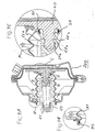
- FIGS. 2A and 2B A second exemplary embodiment is shown in FIGS. 2A and 2B the articulated attachment of the invention Piston rod 30 shown on the rotary lever 50.
- the clamp in this embodiment from a sleeve-like part that in its upper area 61 includes the piston rod 30 and with several spring tabs 62 into a circumferential recess 31 of the piston rod 30 intervenes.
- the sleeve 60 consists of two side tabs 64a and 64b, which the rotary lever 50th embrace laterally and with the help of trained in them Engage holes 63 in pin-shaped projections 51, the are formed on the side of the rotary lever 50.
- the piston rod 30 is therefore pivotable on the rotary lever 50 in the plane of rotation attached.
- the attachment of the piston rod 30 to the rotary lever 50 is particularly easy with this sleeve: it is only necessary, the piston rod 30 in the insert hemispherical recess of the rotary lever 50 and then push the sleeve 60 onto the piston rod 30, the tabs 64a and 64b slightly outwards pressed and inserted with their holes 63 into the projections 51 become; the spring tabs 62 also slide in the circumferential recess 31 of the piston rod 30 and lock this.
- FIGS. 3A to 3C show a third exemplary embodiment the articulated attachment of the invention Piston rod 30 shown on the rotary lever 50.
- this variant consists of the clamp 60 from a lower part 65, the suitably articulated on the circumference of the rotary lever 50 sits and up from the two spring clips 66a and 66b run with the help of a respective hook 67a or 67b through an associated bore in the piston rod 30 can be introduced and in a corresponding recess Snap 21a of shoulder 21 of piston plate 20 into place.
- the clamp 60 consists of a suitably shaped Metal rod or a thick wire in its upper Area runs like a coil spring and in its lower end ends in a kind of hook that on the rotary lever 50 snaps into place. Because the coil spring section the Piston rod 30 locked only by spring pressure, designed assembly and disassembly in this embodiment particularly easy. The production is also at this variant of the clamp is relatively inexpensive.
Landscapes
- Engineering & Computer Science (AREA)
- Mechanical Engineering (AREA)
- General Engineering & Computer Science (AREA)
- Transportation (AREA)
- Braking Arrangements (AREA)
Description
- Figur 1
- anhand einer Teil-Querschnittsansicht durch eine Zuspannvorrichtung 10 und durch einen Bremszylinder 200 ein erstes Ausführungsbeispiel der Erfindung;
- Figur 2A und 2B
- anhand von Querschnittsansichten ein zweites Ausführungsbeispiel der Erfindung;
- Figur 3a
- anhand einer Querschnittsansicht durch den Bremszylinder 200 ein drittes Ausführungsbeispiel der Erfindung, wobei in den Fig. 3B und 3C vergrößerte Ansichten von Bereichen B bzw. C der Fig.3A gezeigt sind; und
- Fig.4
- anhand einer Querschnittsansicht durch den Bremszylinder 200 ein viertes Ausführungsbeispiel der Erfindung.
Claims (6)
- Bremszuspannvorrichtung (1), insbesondere zum Zuspannen der Bremsscheiben (2) von mit einer Druckluft-Bremsanlage ausgestatteten Nutz- und Schienenfahrzeugen, mit einer Kolbenstange (30), die über Druckluft und/oder ein Feststell-Bremselement in einer vorgegebenen Betätigungsrichtung (X) im wesentlichen linear verstellbar ist und ein Bremszuspannelement (50) betätigt, das im Laufe seiner Betätigung eine von der Betätigungsrichtung (X) abweichende, etwa kreisausschnittförmige Bahn beschreibt, wobei ein Druckluftbremszylinder (2) vorgesehen ist, der einen in Betätigungsrichtung (X) beaufschlagbaren Kolbenteller (20) aufweist und wobei die Kolbenstange (30) gelenkig am Bremszuspannelement (50) befestigbar ist, dadurch gekennzeichnet, daß die Kolbenstange (30) lösbar am Kolbenteller (20) und mittels eines Klemmbügels (60) lösbar am Drehhebel (50) befestigbar ist.
- Bremszuspannvorrichtung nach Anspruch 1, dadurch gekennzeichnet, daß die Kolbenstange (30) an ihrem Ende halbkugelförmig ausgebildet ist und zur Bildung eines Kugelpfannengelenks in eine entsprechende halbkugelförmige Ausnehmung des Bremszuspannelementes (50) eingreift.
- Bremszuspannvorrichtung nach Anspruch 2, dadurch gekennzeichnet, daß der Klemmbügel als Federbügel (60) ausgebildet ist.
- Bremszuspannvorrichtung nach Anspruch 2 oder 3, dadurch gekennzeichnet, daß an der Kolbenstange (30) oder am Bremszuspannelement (50) stiftförmige Vorsprünge (51) ausgebildet sind, in denen der Klemmbügel (60) schwenkbar gelagert ist, während im jeweils anderen Teil (d.h. Bremszuspannelement bzw. Kolbenstange) eine vorzugsweise umlaufend ausgebildete Ausnehmung (31) ausgebildet ist, in die ein als Klemmelement ausgebildetes Teil des Klemmbügels (60) einrastet.
- Bremszuspannvorrichtung nach einem der Ansprüche 1 bis 4, dadurch gekennzeichnet, daß in der Kolbenstange (30) eine runde Ausnehmung (33) ausgebildet ist, in die ein stiftförmiger Ansatz (21) des Kolbentellers (20) einführbar ist.
- Bremszuspannvorrichtung nach einem der Ansprüche 1 bis 5, dadurch gekennzeichnet, daß die Öffnung (90), über die die Kolbenstange (30) in das Gehäuse (11) der Bremszuspannvorrichtung (1) eintaucht, um das Bremszuspannelement (50) zu beaufschlagen, mittels eines Faltenbalgs (91) abgedichtet ist, der einerseits am Umfang der Öffnung (90) und andererseits an dem dem Bremszuspannelement (50) abgewandten Ende der Kolbenstange (30) befestigt ist.
Applications Claiming Priority (2)
| Application Number | Priority Date | Filing Date | Title |
|---|---|---|---|
| DE19518513 | 1995-05-19 | ||
| DE19518513A DE19518513C2 (de) | 1995-05-19 | 1995-05-19 | Bremszuspannvorrichtung |
Publications (2)
| Publication Number | Publication Date |
|---|---|
| EP0743469A1 EP0743469A1 (de) | 1996-11-20 |
| EP0743469B1 true EP0743469B1 (de) | 2001-01-10 |
Family
ID=7762409
Family Applications (1)
| Application Number | Title | Priority Date | Filing Date |
|---|---|---|---|
| EP96105532A Expired - Lifetime EP0743469B1 (de) | 1995-05-19 | 1996-04-09 | Bremszuspannvorrichtung |
Country Status (2)
| Country | Link |
|---|---|
| EP (1) | EP0743469B1 (de) |
| DE (2) | DE19518513C2 (de) |
Cited By (1)
| Publication number | Priority date | Publication date | Assignee | Title |
|---|---|---|---|---|
| DE102009031559A1 (de) | 2008-07-04 | 2010-01-07 | Knorr-Bremse Systeme für Nutzfahrzeuge GmbH | Pneumatisch betätigbare Scheibenbremse sowie Bremszylinder |
Families Citing this family (8)
| Publication number | Priority date | Publication date | Assignee | Title |
|---|---|---|---|---|
| DE19756519A1 (de) * | 1996-12-18 | 1998-10-15 | Knorr Bremse Systeme | Bremszylinder für druckluftbetätigte Bremsen |
| DE19815406A1 (de) | 1998-04-06 | 1999-10-07 | Wabco Perrot Bremsen Gmbh | Bremsenzuspannvorrichtung |
| DE19858707B4 (de) * | 1998-12-18 | 2004-12-09 | Knorr-Bremse Systeme für Nutzfahrzeuge GmbH | Bremszylinder für eine Scheibenbremse |
| DE10027375A1 (de) * | 2000-06-02 | 2001-12-06 | Zahnradfabrik Friedrichshafen | Zahnräder-Wechselgetriebe |
| GB2455986B (en) | 2007-12-24 | 2011-12-07 | Meritor Heavy Vehicle Braking | Retaining formation |
| DE102009017904A1 (de) * | 2009-04-17 | 2010-10-21 | Knorr-Bremse Systeme für Nutzfahrzeuge GmbH | Scheibenbremse für ein Nutzfahrzeug |
| DE102012006090B4 (de) * | 2012-03-26 | 2017-11-16 | Knorr-Bremse Systeme für Nutzfahrzeuge GmbH | Scheibenbremse |
| DE102016103187A1 (de) | 2016-02-24 | 2017-08-24 | Knorr-Bremse Systeme für Nutzfahrzeuge GmbH | Scheibenbremse mit einer Schnellanlegevorrichtung |
Citations (1)
| Publication number | Priority date | Publication date | Assignee | Title |
|---|---|---|---|---|
| EP0740085A1 (de) * | 1995-04-24 | 1996-10-30 | PERROT BREMSEN GmbH | Scheibenbremse |
Family Cites Families (7)
| Publication number | Priority date | Publication date | Assignee | Title |
|---|---|---|---|---|
| US3802539A (en) * | 1973-01-02 | 1974-04-09 | Stamco Inc | Disc brake apparatus |
| US4036329A (en) * | 1975-11-12 | 1977-07-19 | Rockwell International Corporation | Disc brake with rotary cam actuated reciprocating pistons |
| US4222310A (en) * | 1978-12-04 | 1980-09-16 | Eaton Corporation | Brake actuator fastener assembly |
| DE3245773A1 (de) * | 1982-12-10 | 1984-06-14 | Karl Friedrich von 2357 Bad Bramstedt Grünberg | Teilbelag-scheibenbremse |
| DE4212382C1 (de) * | 1992-04-13 | 1994-02-03 | Knorr Bremse Ag | Druckluftbetätigte Scheibenbremse |
| DE4314720A1 (de) * | 1993-05-04 | 1994-11-10 | Knorr Bremse Ag | Druckluftbetätigte Scheibenbremse |
| DE4339764A1 (de) * | 1993-11-22 | 1995-05-24 | Perrot Bremse Gmbh Deutsche | Zuspannvorrichtung für eine Scheibenbremse |
-
1995
- 1995-05-19 DE DE19518513A patent/DE19518513C2/de not_active Expired - Lifetime
-
1996
- 1996-04-09 EP EP96105532A patent/EP0743469B1/de not_active Expired - Lifetime
- 1996-04-09 DE DE59606287T patent/DE59606287D1/de not_active Expired - Lifetime
Patent Citations (1)
| Publication number | Priority date | Publication date | Assignee | Title |
|---|---|---|---|---|
| EP0740085A1 (de) * | 1995-04-24 | 1996-10-30 | PERROT BREMSEN GmbH | Scheibenbremse |
Cited By (5)
| Publication number | Priority date | Publication date | Assignee | Title |
|---|---|---|---|---|
| DE102009031559A1 (de) | 2008-07-04 | 2010-01-07 | Knorr-Bremse Systeme für Nutzfahrzeuge GmbH | Pneumatisch betätigbare Scheibenbremse sowie Bremszylinder |
| WO2010000473A1 (de) * | 2008-07-04 | 2010-01-07 | Knorr-Bremse Systeme für Nutzfahrzeuge GmbH | Pneumatisch betätigbare scheibenbremse sowie bremszylinder |
| CN102076985A (zh) * | 2008-07-04 | 2011-05-25 | 克诺尔商用车制动系统有限公司 | 可气动操纵的盘式制动器以及制动缸 |
| US8286759B2 (en) | 2008-07-04 | 2012-10-16 | Knorr-Bremse Systeme Fuer Nutzfahrzeuge Gmbh | Pneumatically actuatable disc brake and brake cylinder |
| CN102076985B (zh) * | 2008-07-04 | 2013-09-04 | 克诺尔商用车制动系统有限公司 | 可气动操纵的盘式制动器以及制动缸 |
Also Published As
| Publication number | Publication date |
|---|---|
| DE59606287D1 (de) | 2001-02-15 |
| DE19518513A1 (de) | 1996-11-21 |
| EP0743469A1 (de) | 1996-11-20 |
| DE19518513C2 (de) | 2002-09-26 |
Similar Documents
| Publication | Publication Date | Title |
|---|---|---|
| DE19526833B4 (de) | Schnellspannsystem | |
| DE69300030T2 (de) | Einstellbare Lenksäuleneinheit für ein Kraftfahrzeug. | |
| DE3514315C2 (de) | Anordnung zur lösbaren festen Verbindung eines Stangenkopfteils eines Kupplungskörpers einer Fluidleitung mit einem festwandigen Element | |
| DE2121381C3 (de) | Zahnstangenlenkung für Kraftfahrzeuge | |
| EP0445591A1 (de) | Einrichtung zum Verbinden einer Lenksäule eines Kraftfahrzeuges mit einem Wellenzapfen eines Lenkgetriebes | |
| EP1557299B1 (de) | Anhängekupplung | |
| WO2014206926A1 (de) | Gelenkvorrichtung zur schwenkbaren verbindung eines ersten mit einem zweiten gelenkarm, sowie spiegelhalterung und spiegel mit derartiger gelenkvorrichtung | |
| WO1987005654A1 (en) | Tumbler for cylindrical lock | |
| DE102007029051A1 (de) | Anhängekupplung für Kraftfahrzeuge | |
| EP0743469B1 (de) | Bremszuspannvorrichtung | |
| DE3411054C2 (de) | ||
| EP0877677B1 (de) | Vorrichtung zur verriegelung eines containers an einem fahrzeugchassis | |
| DE2003028A1 (de) | Scheibenbremse | |
| EP4012200B1 (de) | Federbelasteter rastbolzen | |
| DE20021682U1 (de) | Rotationsarretierung für unterschiedliche Positionen einer Mine in einem Schreibgerät | |
| EP1879788A1 (de) | Sicherungseinrichtung für steuerkopflagerungen und verfahren zur sicherung von steuerkopflagerungen | |
| WO1997028020A9 (de) | Vorrichtung zur verriegelung eines containers an einem fahrzeugchassis | |
| EP1386761B1 (de) | Höhenverstellbare Anhängerkupplung | |
| CH669633A5 (de) | ||
| DE10046717A1 (de) | Schließvorrichtung für eine Fahrzeugtür | |
| EP1410971B1 (de) | Lenksäule | |
| DE29505752U1 (de) | Vorrichtung zum Verbinden von Platten mittels Verschraubung | |
| EP0212322A2 (de) | Abnehmbare Anhängerkupplung | |
| WO2007012396A1 (de) | Kugelgelenk und dichtungsmanschette für ein solches kugelgelenk | |
| EP0221255A2 (de) | Fahrzeugspiegel |
Legal Events
| Date | Code | Title | Description |
|---|---|---|---|
| PUAI | Public reference made under article 153(3) epc to a published international application that has entered the european phase |
Free format text: ORIGINAL CODE: 0009012 |
|
| 17P | Request for examination filed |
Effective date: 19960919 |
|
| AK | Designated contracting states |
Kind code of ref document: A1 Designated state(s): DE FR GB IT |
|
| 17Q | First examination report despatched |
Effective date: 19981126 |
|
| GRAG | Despatch of communication of intention to grant |
Free format text: ORIGINAL CODE: EPIDOS AGRA |
|
| GRAG | Despatch of communication of intention to grant |
Free format text: ORIGINAL CODE: EPIDOS AGRA |
|
| GRAH | Despatch of communication of intention to grant a patent |
Free format text: ORIGINAL CODE: EPIDOS IGRA |
|
| GRAH | Despatch of communication of intention to grant a patent |
Free format text: ORIGINAL CODE: EPIDOS IGRA |
|
| GRAA | (expected) grant |
Free format text: ORIGINAL CODE: 0009210 |
|
| AK | Designated contracting states |
Kind code of ref document: B1 Designated state(s): DE FR GB IT |
|
| ITF | It: translation for a ep patent filed | ||
| REF | Corresponds to: |
Ref document number: 59606287 Country of ref document: DE Date of ref document: 20010215 |
|
| ET | Fr: translation filed | ||
| GBT | Gb: translation of ep patent filed (gb section 77(6)(a)/1977) |
Effective date: 20010323 |
|
| PLBE | No opposition filed within time limit |
Free format text: ORIGINAL CODE: 0009261 |
|
| STAA | Information on the status of an ep patent application or granted ep patent |
Free format text: STATUS: NO OPPOSITION FILED WITHIN TIME LIMIT |
|
| REG | Reference to a national code |
Ref country code: GB Ref legal event code: IF02 |
|
| 26N | No opposition filed | ||
| PGFP | Annual fee paid to national office [announced via postgrant information from national office to epo] |
Ref country code: GB Payment date: 20040407 Year of fee payment: 9 |
|
| PGFP | Annual fee paid to national office [announced via postgrant information from national office to epo] |
Ref country code: FR Payment date: 20040408 Year of fee payment: 9 |
|
| PG25 | Lapsed in a contracting state [announced via postgrant information from national office to epo] |
Ref country code: IT Free format text: LAPSE BECAUSE OF NON-PAYMENT OF DUE FEES Effective date: 20050409 Ref country code: GB Free format text: LAPSE BECAUSE OF NON-PAYMENT OF DUE FEES Effective date: 20050409 |
|
| GBPC | Gb: european patent ceased through non-payment of renewal fee |
Effective date: 20050409 |
|
| PG25 | Lapsed in a contracting state [announced via postgrant information from national office to epo] |
Ref country code: FR Free format text: LAPSE BECAUSE OF NON-PAYMENT OF DUE FEES Effective date: 20051230 |
|
| REG | Reference to a national code |
Ref country code: FR Ref legal event code: ST Effective date: 20051230 |
|
| PGFP | Annual fee paid to national office [announced via postgrant information from national office to epo] |
Ref country code: DE Payment date: 20150422 Year of fee payment: 20 |
|
| REG | Reference to a national code |
Ref country code: DE Ref legal event code: R071 Ref document number: 59606287 Country of ref document: DE |