EP0743511A1 - Broche à entraînement électrique pour une machine à équilibrer les outils - Google Patents
Broche à entraînement électrique pour une machine à équilibrer les outils Download PDFInfo
- Publication number
- EP0743511A1 EP0743511A1 EP96201297A EP96201297A EP0743511A1 EP 0743511 A1 EP0743511 A1 EP 0743511A1 EP 96201297 A EP96201297 A EP 96201297A EP 96201297 A EP96201297 A EP 96201297A EP 0743511 A1 EP0743511 A1 EP 0743511A1
- Authority
- EP
- European Patent Office
- Prior art keywords
- spindle
- tool
- spindle shaft
- stator
- taper
- Prior art date
- Legal status (The legal status is an assumption and is not a legal conclusion. Google has not performed a legal analysis and makes no representation as to the accuracy of the status listed.)
- Withdrawn
Links
- 238000003754 machining Methods 0.000 description 3
- 230000005540 biological transmission Effects 0.000 description 2
- 238000000605 extraction Methods 0.000 description 2
- 239000011521 glass Substances 0.000 description 1
- 239000002184 metal Substances 0.000 description 1
- 239000002023 wood Substances 0.000 description 1
Images
Classifications
-
- G—PHYSICS
- G01—MEASURING; TESTING
- G01M—TESTING STATIC OR DYNAMIC BALANCE OF MACHINES OR STRUCTURES; TESTING OF STRUCTURES OR APPARATUS, NOT OTHERWISE PROVIDED FOR
- G01M1/00—Testing static or dynamic balance of machines or structures
- G01M1/02—Details of balancing machines or devices
- G01M1/06—Adaptation of drive assemblies for receiving the body to be tested
-
- B—PERFORMING OPERATIONS; TRANSPORTING
- B23—MACHINE TOOLS; METAL-WORKING NOT OTHERWISE PROVIDED FOR
- B23Q—DETAILS, COMPONENTS, OR ACCESSORIES FOR MACHINE TOOLS, e.g. ARRANGEMENTS FOR COPYING OR CONTROLLING; MACHINE TOOLS IN GENERAL CHARACTERISED BY THE CONSTRUCTION OF PARTICULAR DETAILS OR COMPONENTS; COMBINATIONS OR ASSOCIATIONS OF METAL-WORKING MACHINES, NOT DIRECTED TO A PARTICULAR RESULT
- B23Q1/00—Members which are comprised in the general build-up of a form of machine, particularly relatively large fixed members
- B23Q1/70—Stationary or movable members for carrying working-spindles for attachment of tools or work
Definitions
- the present invention relates to an electric spindle for a tool balancing machine.
- balancing machines have been marketed which are capable of determining unbalancing of the tool-toolholder taper assembly and of indicating the size of a compensation counterweight and the position wherein this counterweight has to be added.
- balancing machines comprise a spindle whereon the toolholder taper is mounted, in order to make it integral with the spindle itself, and an external electric motor which, by means of a typically belt transmission, rotates the spindle.
- Appropriately positioned sensors allow the extent of unbalancing and the point of greatest weight to be determined.
- the main disadvantage of known balancing machines lies in the fact that, during the balancing operation, the tool (the tool-toolholder taper assembly) is not in the same conditions wherein it would be were it mounted on the spindle of the machine tool, in that in current machine tools no belt transmission is provided for moving the spindle.
- the object of the present invention is that of providing an improved spindle for a balancing machine, which avoids the aforementioned problem.
- an electric spindle for a tool balancing machine comprising an external casing and an internal spindle shaft whereon a tool to be balanced is mounted, and an electric motor for rotating the spindle shaft, comprising a stator and a rotor, coaxial and internal to the stator, characterised in that said rotor is mounted directly on the spindle shaft, while said stator is attached inside said casing.
- An electric spindle according to the present invention groups together in its interior the spindle shaft and the motor for rotating the spindle shaft. In this way, during balancing, the tool to be balanced, or more specifically the tool-toolholder taper assembly, is in the same conditions which it experiences during machining on a machine tool.
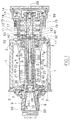
- an electric spindle according to the invention for a machine for balancing machining tools is shown therein in axial section.
- the electric spindle shown comprises a casing 1 which is substantially cylindrical and closed at its two ends by a front flange 2 and by a rear flange 3.
- an electric motor inside the casing 1 an electric motor is housed comprising a stator 4, attached to the internal wall of the casing 1, and a rotor 5 coaxial to the stator 4.
- the rotor 5 is keyed onto a hollow shaft 6 forming the rotating part, or spindle shaft in proper terms, whereon a toolholder taper is mounted with the tool to be balanced.
- the spindle shaft 6 is supported at its ends by the flanges 2 and 3, by means of two ball bearings 7 and 8.
- the electric spindle shown is also provided with a clamping device for toolholder tapers of varying sizes, forming the object of a co-pending patent application in the name of the same applicant.
- This clamping device comprises an adapter 9 mounted in the front by means of screws 50 to the spindle shaft 6; the adapter 9 holds a toolholder taper 10 comprising a shank 28.
- the adapter 9 and the toolholder taper 10 have dimensions in agreement with the standard ISO 40.
- the adapter 9, being screw-mounted, is interchangeable and can be replaced by an adapter for toolholder tapers of different sizes, for example according to the standard ISO 30 (not shown).
- a ring nut 52 On the threaded rear end of the spindle shaft 6 a ring nut 52 is screwed and bears reference notches for a sensor 53.
- the sensor 53 sends a signal to an electronic control unit (not shown) to determine an angular reference.
- a cylindrical sleeve 11 Mounted at the rear flange 3 is a cylindrical sleeve 11 wherein a cylinder 12 is inserted.
- a cylinder 12 In the cylinder 12, closed at the rear by a sealed cover 14, an internally hollow piston 13 is slidingly housed and elastically forced towards the cover 14 by a spiral spring 15.
- an internally hollow tension shaft 16 is also housed, on whose threaded head a ring nut 18 is screwed.
- the tension shaft 16 is inserted slidingly in the spindle shaft 6.
- This end of the tension shaft 16 inserted in the spindle shaft 6 is threaded and a first bush 20 is screwed thereon and slidingly housed in the spindle shaft 6.
- the first bush 20 houses, in respective holes positioned in a circumferential series at 120° one from the other, a first triad of balls 24.
- an annular groove 56 is also formed in the first bush 20, next to the circumferential series of balls 24, an annular groove 56 is also formed.
- an annular groove 58 is formed of adequate size to hold the balls 24 at least partially.
- a second bush 21 is slidingly housed, screwed onto a tie rod 22 elastically forced by a third spiral spring 23 in the direction of the shank 28 of the toolholder taper 10.
- the second bush 21 houses, in respective holes positioned in a circumferential series at 120° one from the other and in an intermediate position between the holes of the first bush 20 (that is to say, the two circumferential series of holes are rotated through 60° one in relation to the other), three balls 25 of a slightly smaller diameter than the balls 24.
- a thrust rod 17 is slidingly inserted and extends also inside the third spiral spring 23, the tie rod 22 and the second bush 21, substantially as far as the end of the shank 28 of the toolholder taper 10.
- Two pins 40 integral with the spindle shaft 6, engage in respective notches formed in the surface of the thrust rod 17 to prevent the latter from rotating in relation to the spindle shaft, and at the same time prevent it from withdrawing when the toolholder taper is removed.
- the head of the tension shaft 16 is threaded internally, and a scrw 59 engages therein to regulate the stroke of the thrust rod 17.
- the toolholder taper 10 is clamped on the spindle shaft 6.
- the first bush 20 is subjected to traction towards the rear part of the electric spindle by the force of the spring 19 on the tension shaft 16, and the balls 24, partially projecting from the holes 26, prevent the extraction of the widened end of the shank 28.
- the friction between the external conical surface of the toolholder taper 10 and the internal conical surface of the adapter 9 makes the taper-tool assembly integral with the spindle shaft 6.
- pressurised air is fed through a hole 29 in the cover 14. This air pushes the piston 13 until it hits against the head of the tension shaft 16. The sliding towards the left of the latter causes the movement of the first bush. When the balls 24 have moved to the annular groove 58, the balls 24 can withdraw into this groove, leaving the shank 28 free.
- the balls 25 are engaged with the shank of this taper.
- An annular ridge 61 on the first bush 20 hits against a similar ridge 62 on the tie rod 22, in order to transmit the force of the spring 19.
- the annular groove 56 allows the balls 25 to withdraw, in order to allow extraction of the shank.
Landscapes
- Physics & Mathematics (AREA)
- General Physics & Mathematics (AREA)
- Engineering & Computer Science (AREA)
- Mechanical Engineering (AREA)
- Turning (AREA)
- Constituent Portions Of Griding Lathes, Driving, Sensing And Control (AREA)
Applications Claiming Priority (2)
| Application Number | Priority Date | Filing Date | Title |
|---|---|---|---|
| ITMI951014A IT1274526B (it) | 1995-05-19 | 1995-05-19 | Elettromandrino per macchina equilibratrice di utensili |
| ITMI951014 | 1995-05-19 |
Publications (1)
| Publication Number | Publication Date |
|---|---|
| EP0743511A1 true EP0743511A1 (fr) | 1996-11-20 |
Family
ID=11371627
Family Applications (1)
| Application Number | Title | Priority Date | Filing Date |
|---|---|---|---|
| EP96201297A Withdrawn EP0743511A1 (fr) | 1995-05-19 | 1996-05-10 | Broche à entraînement électrique pour une machine à équilibrer les outils |
Country Status (4)
| Country | Link |
|---|---|
| EP (1) | EP0743511A1 (fr) |
| JP (1) | JPH08318403A (fr) |
| CN (1) | CN1158288A (fr) |
| IT (1) | IT1274526B (fr) |
Cited By (6)
| Publication number | Priority date | Publication date | Assignee | Title |
|---|---|---|---|---|
| WO2000045983A1 (fr) * | 1999-02-01 | 2000-08-10 | Franz Haimer Maschinenbau Kg | Dispositif de serrage pour la fixation d'un element de machine rotatif, et machine a equilibrer pourvue d'un tel dispositif de serrage |
| EP0828338B1 (fr) * | 1996-09-09 | 2002-12-04 | F.M. Elettromeccanica s.r.l. | Dispositif de verrouillage d'un embrayage mobile pour un rotor d'une broche électrique |
| EP1367374A3 (fr) * | 2002-05-14 | 2004-09-01 | Carlo Buzzi | Machine d'équilibrage de corps rotatifs |
| WO2004087353A1 (fr) | 2003-03-31 | 2004-10-14 | Nsk Ltd. | Ensemble arbre principal et machine-outil comportant ledit ensemble |
| DE102010044849A1 (de) * | 2010-09-09 | 2012-03-15 | Hofmann Maschinen- Und Anlagenbau Gmbh | Vorrichtung zur Drehlagerung eines auszuwuchtenden Rotors |
| KR101167003B1 (ko) | 2005-12-22 | 2012-07-24 | 두산인프라코어 주식회사 | 스핀들 카트리지의 분리를 용이토록 한 모터 내장형 스핀들장치 |
Families Citing this family (5)
| Publication number | Priority date | Publication date | Assignee | Title |
|---|---|---|---|---|
| CN100436050C (zh) * | 2007-06-07 | 2008-11-26 | 浙江大学 | 全自动平衡机切削点自动定位装置 |
| JP5233517B2 (ja) * | 2008-08-28 | 2013-07-10 | 日本精工株式会社 | 主軸装置及びそれを備えた工作機械 |
| JP5569605B2 (ja) * | 2013-01-25 | 2014-08-13 | 日本精工株式会社 | 主軸装置及びそれを備えた工作機械 |
| CN105171007B (zh) * | 2015-08-25 | 2018-05-25 | 上海嘉准机械设备有限公司 | 一种交流电主轴单元及其驱动方法 |
| CN106735334A (zh) * | 2017-01-18 | 2017-05-31 | 深圳数马电子技术有限公司 | 电磁铁松刀式自动换刀电主轴 |
Citations (3)
| Publication number | Priority date | Publication date | Assignee | Title |
|---|---|---|---|---|
| CH573796A5 (fr) * | 1973-08-14 | 1976-03-31 | Schleith & Co | |
| DE4037745A1 (de) * | 1989-12-18 | 1991-06-20 | Osawa Seisakusho Co | Auswuchtmaschine |
| EP0525405A1 (fr) * | 1991-07-08 | 1993-02-03 | Gildemeister Ag | Broche pour pièces de travail d'un tour |
-
1995
- 1995-05-19 IT ITMI951014A patent/IT1274526B/it active IP Right Grant
-
1996
- 1996-05-10 EP EP96201297A patent/EP0743511A1/fr not_active Withdrawn
- 1996-05-15 JP JP8120461A patent/JPH08318403A/ja active Pending
- 1996-05-17 CN CN96110718.9A patent/CN1158288A/zh active Pending
Patent Citations (3)
| Publication number | Priority date | Publication date | Assignee | Title |
|---|---|---|---|---|
| CH573796A5 (fr) * | 1973-08-14 | 1976-03-31 | Schleith & Co | |
| DE4037745A1 (de) * | 1989-12-18 | 1991-06-20 | Osawa Seisakusho Co | Auswuchtmaschine |
| EP0525405A1 (fr) * | 1991-07-08 | 1993-02-03 | Gildemeister Ag | Broche pour pièces de travail d'un tour |
Cited By (13)
| Publication number | Priority date | Publication date | Assignee | Title |
|---|---|---|---|---|
| EP0828338B1 (fr) * | 1996-09-09 | 2002-12-04 | F.M. Elettromeccanica s.r.l. | Dispositif de verrouillage d'un embrayage mobile pour un rotor d'une broche électrique |
| WO2000045983A1 (fr) * | 1999-02-01 | 2000-08-10 | Franz Haimer Maschinenbau Kg | Dispositif de serrage pour la fixation d'un element de machine rotatif, et machine a equilibrer pourvue d'un tel dispositif de serrage |
| US6612791B1 (en) | 1999-02-01 | 2003-09-02 | Franz Haimer Maschinenbau Kg | Clamping device for clamping a rotating machine element and a balancing machine having comprising such a clamping device |
| EP1367374A3 (fr) * | 2002-05-14 | 2004-09-01 | Carlo Buzzi | Machine d'équilibrage de corps rotatifs |
| EP1609549A4 (fr) * | 2003-03-31 | 2008-04-16 | Nsk Ltd | Ensemble arbre principal et machine-outil comportant ledit ensemble |
| US7311482B2 (en) | 2003-03-31 | 2007-12-25 | Nsk Ltd. | Main shaft device and machine tool with the same |
| WO2004087353A1 (fr) | 2003-03-31 | 2004-10-14 | Nsk Ltd. | Ensemble arbre principal et machine-outil comportant ledit ensemble |
| CN100556588C (zh) * | 2003-03-31 | 2009-11-04 | 日本精工株式会社 | 主轴装置 |
| US7690873B2 (en) | 2003-03-31 | 2010-04-06 | Nsk Ltd. | Main shaft device and machine tool with the same |
| US8052362B2 (en) | 2003-03-31 | 2011-11-08 | Nsk, Ltd. | Main shaft device and machine tool with the same |
| KR101167003B1 (ko) | 2005-12-22 | 2012-07-24 | 두산인프라코어 주식회사 | 스핀들 카트리지의 분리를 용이토록 한 모터 내장형 스핀들장치 |
| DE102010044849A1 (de) * | 2010-09-09 | 2012-03-15 | Hofmann Maschinen- Und Anlagenbau Gmbh | Vorrichtung zur Drehlagerung eines auszuwuchtenden Rotors |
| US8875572B2 (en) | 2010-09-09 | 2014-11-04 | Hofmann Maschinen-Und Anlagenbau Gmbh | Apparatus for rotatably mounting a rotor to be balanced |
Also Published As
| Publication number | Publication date |
|---|---|
| IT1274526B (it) | 1997-07-17 |
| ITMI951014A1 (it) | 1996-11-19 |
| JPH08318403A (ja) | 1996-12-03 |
| CN1158288A (zh) | 1997-09-03 |
| ITMI951014A0 (it) | 1995-05-19 |
Similar Documents
| Publication | Publication Date | Title |
|---|---|---|
| US5342155A (en) | Spindle extension with self-contained pull-stud draw bar assembly | |
| US5997223A (en) | High speed drilling spindle with reciprocating ceramic shaft and edoubl-gripping centrifugal chuck | |
| US4957398A (en) | Two-section tool spindle having a channel for carrying pressurized fluid | |
| DK166973B1 (da) | Tachogenerator til anbringelse paa en drivaksel | |
| EP0988910A2 (fr) | Porte-outil | |
| JP2512454Y2 (ja) | 回転工具 | |
| FI79046B (fi) | Borrhammare med en styrcylinder foer slaganordningen. | |
| US20190061085A1 (en) | Spindle apparatus for use on a numerically controlled machine tool | |
| CN110695142A (zh) | 无中心孔细长轴类零件校直装置 | |
| EP0743119A1 (fr) | Dispositif pour la fixation sur une broche de portes-outils à queues coniques de différentes dimensions | |
| US4407615A (en) | Tool-clamping device | |
| JPH08318403A (ja) | 工具つりあい機の電気式スピンドル | |
| US8454283B2 (en) | Motor-driven working spindle for a machine tool | |
| US8161853B2 (en) | Centering bushing for centering material bars | |
| US6053508A (en) | Device for the centric and/or imbalance-free holding of workpieces or tools | |
| CN104334301A (zh) | 平衡适配器 | |
| JPH01264748A (ja) | 増速機構内蔵工具アダプタ | |
| JP2002086305A (ja) | 円筒形端部を備えるワークピースを主軸側で心出しおよび締付けするための装置 | |
| IT9048580A1 (it) | Equilibratrice per misurare l'entita' di squilibrio residuo di corpi rotanti, quali utensili rotanti. | |
| CN208528926U (zh) | 高精度旋转夹持机构 | |
| US4421443A (en) | High speed machine tool spindle assembly | |
| US2950636A (en) | Safety drivers for gun drills | |
| US20210197297A1 (en) | Tool holder for a machining tool with depth-control stop and machining device | |
| US6220143B1 (en) | Rotary cylinder device | |
| JPH0724695A (ja) | 工作機主軸の回転位置センサ |
Legal Events
| Date | Code | Title | Description |
|---|---|---|---|
| PUAI | Public reference made under article 153(3) epc to a published international application that has entered the european phase |
Free format text: ORIGINAL CODE: 0009012 |
|
| AK | Designated contracting states |
Kind code of ref document: A1 Designated state(s): CH DE FR GB IT LI |
|
| STAA | Information on the status of an ep patent application or granted ep patent |
Free format text: STATUS: THE APPLICATION IS DEEMED TO BE WITHDRAWN |
|
| 18D | Application deemed to be withdrawn |
Effective date: 19970521 |