EP0743579A2 - Procédé de commande d'une machine outil à commande numérique ou d'un robot - Google Patents
Procédé de commande d'une machine outil à commande numérique ou d'un robot Download PDFInfo
- Publication number
- EP0743579A2 EP0743579A2 EP96106924A EP96106924A EP0743579A2 EP 0743579 A2 EP0743579 A2 EP 0743579A2 EP 96106924 A EP96106924 A EP 96106924A EP 96106924 A EP96106924 A EP 96106924A EP 0743579 A2 EP0743579 A2 EP 0743579A2
- Authority
- EP
- European Patent Office
- Prior art keywords
- axis
- limit switch
- interpolation
- axes
- braking
- Prior art date
- Legal status (The legal status is an assumption and is not a legal conclusion. Google has not performed a legal analysis and makes no representation as to the accuracy of the status listed.)
- Granted
Links
Images

Classifications
-
- G—PHYSICS
- G05—CONTROLLING; REGULATING
- G05B—CONTROL OR REGULATING SYSTEMS IN GENERAL; FUNCTIONAL ELEMENTS OF SUCH SYSTEMS; MONITORING OR TESTING ARRANGEMENTS FOR SUCH SYSTEMS OR ELEMENTS
- G05B19/00—Program-control systems
- G05B19/02—Program-control systems electric
- G05B19/18—Numerical control [NC], i.e. automatically operating machines, in particular machine tools, e.g. in a manufacturing environment, so as to execute positioning, movement or co-ordinated operations by means of program data in numerical form
- G05B19/41—Numerical control [NC], i.e. automatically operating machines, in particular machine tools, e.g. in a manufacturing environment, so as to execute positioning, movement or co-ordinated operations by means of program data in numerical form characterised by interpolation, e.g. the computation of intermediate points between programmed end points to define the path to be followed and the rate of travel along that path
- G05B19/4103—Digital interpolation
-
- G—PHYSICS
- G05—CONTROLLING; REGULATING
- G05B—CONTROL OR REGULATING SYSTEMS IN GENERAL; FUNCTIONAL ELEMENTS OF SUCH SYSTEMS; MONITORING OR TESTING ARRANGEMENTS FOR SUCH SYSTEMS OR ELEMENTS
- G05B2219/00—Program-control systems
- G05B2219/30—Nc systems
- G05B2219/34—Director, elements to supervisory
- G05B2219/34095—Look ahead segment calculation
-
- G—PHYSICS
- G05—CONTROLLING; REGULATING
- G05B—CONTROL OR REGULATING SYSTEMS IN GENERAL; FUNCTIONAL ELEMENTS OF SUCH SYSTEMS; MONITORING OR TESTING ARRANGEMENTS FOR SUCH SYSTEMS OR ELEMENTS
- G05B2219/00—Program-control systems
- G05B2219/30—Nc systems
- G05B2219/34—Director, elements to supervisory
- G05B2219/34188—Safety, stop, slowdown interpolator if speed, position, torque error too large
-
- G—PHYSICS
- G05—CONTROLLING; REGULATING
- G05B—CONTROL OR REGULATING SYSTEMS IN GENERAL; FUNCTIONAL ELEMENTS OF SUCH SYSTEMS; MONITORING OR TESTING ARRANGEMENTS FOR SUCH SYSTEMS OR ELEMENTS
- G05B2219/00—Program-control systems
- G05B2219/30—Nc systems
- G05B2219/34—Director, elements to supervisory
- G05B2219/34189—On each axis, for each block, a software limit switch, for safe slow down
-
- G—PHYSICS
- G05—CONTROLLING; REGULATING
- G05B—CONTROL OR REGULATING SYSTEMS IN GENERAL; FUNCTIONAL ELEMENTS OF SUCH SYSTEMS; MONITORING OR TESTING ARRANGEMENTS FOR SUCH SYSTEMS OR ELEMENTS
- G05B2219/00—Program-control systems
- G05B2219/30—Nc systems
- G05B2219/43—Speed, acceleration, deceleration control ADC
- G05B2219/43008—Deceleration and stopping
-
- G—PHYSICS
- G05—CONTROLLING; REGULATING
- G05B—CONTROL OR REGULATING SYSTEMS IN GENERAL; FUNCTIONAL ELEMENTS OF SUCH SYSTEMS; MONITORING OR TESTING ARRANGEMENTS FOR SUCH SYSTEMS OR ELEMENTS
- G05B2219/00—Program-control systems
- G05B2219/30—Nc systems
- G05B2219/43—Speed, acceleration, deceleration control ADC
- G05B2219/43009—Acceleration deceleration for each block of data, segment
-
- G—PHYSICS
- G05—CONTROLLING; REGULATING
- G05B—CONTROL OR REGULATING SYSTEMS IN GENERAL; FUNCTIONAL ELEMENTS OF SUCH SYSTEMS; MONITORING OR TESTING ARRANGEMENTS FOR SUCH SYSTEMS OR ELEMENTS
- G05B2219/00—Program-control systems
- G05B2219/30—Nc systems
- G05B2219/43—Speed, acceleration, deceleration control ADC
- G05B2219/43064—Brake, decelerate at least one axis at maximum
Definitions
- the invention relates to a method for operating a numerically controlled multi-axis machine tool or a robot according to a respectively predetermined program, which, after block preparation in an interpolator, determines target values for controlling the axes in interpolation steps, at least one of the axes being switched on by a software limit switch a predeterminable end position can be limited.
- the axis drives are usually provided with hardware limit switches.
- some axes can also be equipped with so-called software limit switches, e.g. to allow the user a freely adjustable working area limitation. The control of the machine tool or the robot must then ensure that the respective axis drives take these additional software limit switches into account or that an axis is prevented from moving beyond its predetermined software limit switch, for example, during the execution of a part program.
- the axle drives run at a certain speed and therefore have a corresponding inertia.
- the axle drives can only be braked with a certain maximum permissible braking acceleration. If the brake is not applied until the software limit switch is exceeded, the problem arises that the axis only comes to a standstill after the predetermined position of the software limit switch, even if the axis has more than the maximum permitted braking acceleration is braked. Passing over the predetermined position of the software limit switch is of course undesirable for safety reasons.
- each software limit switch was provided with an additional software pre-limit switch and that in the area between the software pre-limit switch and the actual software limit switch the corresponding final drive was operated at a greatly reduced maximum speed.
- a reduced maximum speed determines the inertia of the axis.
- the object of the invention is to develop a method of the type mentioned at the outset such that an axis with a software limit switch does not come to a standstill behind the predetermined position, and that the maximum speed of the axis does not is unnecessarily reduced and that braking is only carried out with the maximum permissible braking acceleration.
- this object is achieved in that in the interpolator each time the next interpolation step is determined for each axis with a software limit switch, whether it takes into account the axial speed to be achieved in the next interpolation step during braking with its maximum axial braking acceleration can come to a standstill at the respective axial end position determined by the respective software limit switch, and that axles for which this is no longer the case are braked with their respective maximum axial braking acceleration instead of the next interpolation step.
- This invention has the advantage that the end position specified by the software limit switch is never exceeded, that braking is only carried out with the maximum permissible axial braking acceleration and that the path speed in the vicinity of the software limit switch is not unnecessarily limited.
- An advantageous further development of the invention consists in that when an axis is braked to limit the end position with its respective maximum axial braking accelerations, this axis is released from the interpolation group and the remaining axes are braked with the machining path-specific braking acceleration.
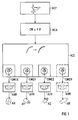
- FIG. 1 shows a block diagram of a numerical control, in which a predetermined numerical control program NCP, after a block preparation NCA in an interpolator NCI, determines setpoints for controlling the axes in interpolation steps.
- a predetermined numerical control program NCP after a block preparation NCA in an interpolator NCI, determines setpoints for controlling the axes in interpolation steps.
- Some of the axes X, Y, Z, R have a software limit switch SWEX, SWEY, SWEZ, SWER which limits the axis movements to a definable end position.
- the software limit switch SWER, the axis controller ARR and the axis drive AR are shown in dash-dotted lines in FIG. 1 to indicate that a software limit switch, an axis controller and an axis drive can be present for any number of axes.
- the software limit switches SWEX, SWEY, SWEZ, SWER check whether the axis drives AX, AY, AZ, AR are below Taking into account their axial speed to be achieved in the next interpolation step when braking with the respectively maximum permissible axial braking acceleration can come to a standstill up to the respective axial end position determined by the respective software limit switch.
- the setpoint for the next interpolation step is output to the corresponding axis controller AXR, AYR, AZR, ARR and the corresponding axis drives AX, AY, AZ, AR are thus controlled.
- a setpoint that corresponds to the respective maximum permissible axial braking acceleration is output to the corresponding axis controller instead of the setpoint for the next interpolation step.
- the corresponding axle drive is thus controlled so that the associated axle is braked with its respective maximum permissible axial braking acceleration.
- Such an axis is released from a possibly existing interpolation group and the remaining axes are additionally braked by the NCI interpolator with the machining path-specific brake acceleration.
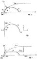
- FIG. 2 and FIG. 3 and FIG. 5 and FIG. 6 the invention is explained using the X axis as an example. The same applies to all other axes with software limit switches.
- FIG. 4 and FIG. 7 show the solutions suitable for FIG. 2 and FIG. 3, or FIG. 5 and FIG. 6.
- FIG. 2, FIG. 5, FIG. 4 and FIG. 7 are diagrams with a horizontal coordinate X, which corresponds to the position along the X axis of the machine tool or the robot, and with a vertical one Coordinate Vx, which corresponds to the speed along this X axis.
- the point SWE corresponds to the end position of the axis movements along the X axis specified by the software limit switch SWEX.
- the curve Vxmax corresponds to the maximum speed along the X axis so that it can come to a standstill in time.
- the Vxmax curve arises from the fact that the maximum speed is calculated for each position along the X-axis, so that the X-axis with its corresponding inertia comes to a standstill exactly at the specified end position SWE if the maximum permissible for the X-axis axial braking acceleration is braked.
- the details of such calculations are part of normal specialist knowledge and do not need to be explained further.
- the point SWVE marks the additional software pre-limit switch of the previous solution.
- the axis drive is limited by a greatly reduced maximum speed Vxbmax.
- curve I1 represents an interpolation curve in the local velocity space X-Vx.
- the interpolation curve I1 is completely below the maximum velocity curve Vxmax. This means that when braking with the maximum permissible axial braking acceleration for the X axis, the X axis would always come to a standstill before the predetermined end position SWE.
- the interpolation curve I1 can therefore be processed unrestrained, at least as far as the X axis is concerned.
- FIG. 3 is a diagram with an interpolated trajectory in the XY space, which is represented by the X and Y axes of the machine tool or the robot is clamped.
- the limit line SWE corresponds to the end position of the axis movements in the X direction specified by the software limit switch SWEX.
- the interpolated circular path curve I1 'in XY space is created by an interpolation association of the X and Y axes.
- the X component of this interpolation group is shown in FIG. 1 as the interpolation curve I1 and, as far as the X axis is concerned, can be processed without being braked, although the interpolated path curve I1 'in the XY space comes very close to the limit line SWE of the software limit switch.
- the X component of this interpolation group is shown in FIG. 4 as an interpolation curve I1 ′′.
- this interpolation curve I1 ′′ is in the area between the software pre-limit switch SWVE and the actual software limit switch SWE and is therefore unnecessarily limited by the reduced maximum speed Vxbmax.
- the processing speed is reduced, although the interpolation curve I1 'is actually always below the maximum speed Vxmax that can still be braked (compare FIG. 4 with FIG. 2).
- the method according to the invention in FIG. 2 is thus a clear improvement over the known method in FIG. 4.
- the curve I2 represents an interpolation curve in the local velocity space X-Vx. From the first interpolation point i0 to the interpolation point i1, the interpolation curve I2 lies completely below the maximum speed curve Vxmax. This means that when braking with the maximum permissible axial braking acceleration for the X axis, the X axis would always come to a standstill before the predetermined end position SWE. For this reason, the interpolation curve I2 is also processed without braking from the first interpolation point i0 to the interpolation point i1. At the interpolation point i1, the interpolator NCI, like any other interpolation point, produces the next interpolation point - in this case point i2 - determined.
- the software limit switch SWEX determines that from point i2, braking with the maximum permissible axial braking acceleration for the X-axis along the dash-dotted braking curve B2 causes the X-axis to come to a standstill at point S2, i.e. only after the specified one SWE end position. This situation can also be seen graphically from the fact that point i2 lies beyond the Vxmax curve.
- the software limit switch SWEX therefore prevents the next interpolation point i2 from being output to the X axis as a setpoint and instead initiates an immediate deceleration starting from point i1 with the maximum permitted axial braking acceleration for the X axis along the dash-dotted braking curve B1 .
- the X axis therefore comes to a standstill at point S1, ie on or immediately before the predetermined end position SWE.
- FIG. 6 is a diagram with an interpolated trajectory in the XY space, which is spanned by the X and Y axes of the machine tool or the robot.
- the limit line SWE corresponds to the end position of the axis movements in the X direction specified by the software limit switch SWEX.
- the interpolated circular path curve I2 'in the XY space is created by an interpolation association of the X and Y axes.
- the X component of the interpolation group is shown in FIG. 5 as an interpolation curve I2 and, as far as the X axis is concerned, can be processed without braking down to point i1 '.
- the further interpolation is interrupted and braking of the X axis is initiated with the maximum permissible axial braking acceleration for the X axis, and is thus released from the interpolation association comprising only two axes in this example.
- the Y-axis remaining from the interpolation group is braked only with the machining path-specific brake acceleration.
- the machining path leaves the intended circular path I2 'and follows the dash-dotted braking curve B1' to a standstill at point S1 ', which is on or immediately before the predetermined end position SWE.
- the end position of the axis movements in the X direction specified by the software limit switch is not exceeded.
- the X component of the interpolation network is shown in FIG. 7 as an interpolation curve I2 ′′.
- this interpolation curve I2 '' is in the area between the software pre-limit switch SWVE and the actual software limit switch SWE and is therefore unnecessarily limited by the reduced maximum speed Vxbmax and the processing speed is therefore reduced.
- this is only recognized when the SWE end position limit specified by the software limit switch is reached at point i1 '' and emergency braking with braking acceleration that exceeds the maximum permissible axial braking accelerations is initiated so that the X axis is soon behind the SWE end position limit on Point Sx comes to a standstill.
- braking is not only carried out with excessive axial braking accelerations, but the limit position limit SWE cannot be maintained either.
Landscapes
- Engineering & Computer Science (AREA)
- Computing Systems (AREA)
- Theoretical Computer Science (AREA)
- Human Computer Interaction (AREA)
- Manufacturing & Machinery (AREA)
- Physics & Mathematics (AREA)
- General Physics & Mathematics (AREA)
- Automation & Control Theory (AREA)
- Numerical Control (AREA)
Applications Claiming Priority (2)
| Application Number | Priority Date | Filing Date | Title |
|---|---|---|---|
| DE19517771 | 1995-05-15 | ||
| DE19517771A DE19517771A1 (de) | 1995-05-15 | 1995-05-15 | Verfahren zum Betrieb einer numerisch gesteuerten Werkzeugmaschine oder eines Roboters |
Publications (3)
| Publication Number | Publication Date |
|---|---|
| EP0743579A2 true EP0743579A2 (fr) | 1996-11-20 |
| EP0743579A3 EP0743579A3 (fr) | 1997-04-23 |
| EP0743579B1 EP0743579B1 (fr) | 1998-11-25 |
Family
ID=7761933
Family Applications (1)
| Application Number | Title | Priority Date | Filing Date |
|---|---|---|---|
| EP96106924A Expired - Lifetime EP0743579B1 (fr) | 1995-05-15 | 1996-05-02 | Procédé de commande d'une machine outil à commande numérique ou d'un robot |
Country Status (3)
| Country | Link |
|---|---|
| EP (1) | EP0743579B1 (fr) |
| AT (1) | ATE173841T1 (fr) |
| DE (2) | DE19517771A1 (fr) |
Cited By (4)
| Publication number | Priority date | Publication date | Assignee | Title |
|---|---|---|---|---|
| EP1901150A1 (fr) * | 2006-09-14 | 2008-03-19 | Abb Research Ltd. | Procédé et dispositif permettant d'éviter les collisions entre un robot industriel et un objet |
| WO2008151810A1 (fr) * | 2007-06-14 | 2008-12-18 | Trumpf Werkzeugmaschinen Gmbh + Co. Kg | Procédé pour optimiser la coordination des mouvements de machines de mesure ou de machines-outils comportant des axes à translation redondante |
| EP2072195A1 (fr) * | 2007-12-19 | 2009-06-24 | KUKA Roboter GmbH | Procédé de commande du mouvement d'un robot à l'intérieur d'une salle de travail |
| DE10338792B4 (de) * | 2003-08-23 | 2009-12-24 | Steuerungstechnik Bbh Gmbh | Verfahren sowie System zur Überwachung der Notstoppfunktion bei Antrieben |
Families Citing this family (6)
| Publication number | Priority date | Publication date | Assignee | Title |
|---|---|---|---|---|
| DE10125445A1 (de) | 2001-05-25 | 2002-12-05 | Kuka Roboter Gmbh | Verfahren zum Steuern der Bewegung eines Roboters |
| US6678582B2 (en) | 2002-05-30 | 2004-01-13 | Kuka Roboter Gmbh | Method and control device for avoiding collisions between cooperating robots |
| DE10226140A1 (de) * | 2002-06-13 | 2004-01-08 | Kuka Roboter Gmbh | Verfahren und Vorrichtung zum Vermeiden von Kollisionen zwischen Industrierobotern und anderen Objekten |
| DE10226853B3 (de) | 2002-06-15 | 2004-02-19 | Kuka Roboter Gmbh | Verfahren zum Begrenzen der Krafteinwirkung eines Roboterteils |
| DE102005010089B4 (de) | 2005-03-04 | 2007-08-30 | Siemens Ag | Verfahren und Einrichtung zum Positionieren eines Elements einer Maschine |
| DE102019125326B3 (de) * | 2019-09-20 | 2020-12-03 | Franka Emika Gmbh | Prognostizierter Bremsbereich eines Robotermanipulators |
Family Cites Families (1)
| Publication number | Priority date | Publication date | Assignee | Title |
|---|---|---|---|---|
| ES2077941T3 (es) * | 1992-07-21 | 1995-12-01 | Siemens Ag | Procedimiento para el frenado optimo en el tiempo, acorde con la trayectoria de los accionamientos axiales de maquinas de control numerico. |
-
1995
- 1995-05-15 DE DE19517771A patent/DE19517771A1/de not_active Withdrawn
-
1996
- 1996-05-02 EP EP96106924A patent/EP0743579B1/fr not_active Expired - Lifetime
- 1996-05-02 AT AT96106924T patent/ATE173841T1/de not_active IP Right Cessation
- 1996-05-02 DE DE59600856T patent/DE59600856D1/de not_active Expired - Fee Related
Cited By (6)
| Publication number | Priority date | Publication date | Assignee | Title |
|---|---|---|---|---|
| DE10338792B4 (de) * | 2003-08-23 | 2009-12-24 | Steuerungstechnik Bbh Gmbh | Verfahren sowie System zur Überwachung der Notstoppfunktion bei Antrieben |
| EP1901150A1 (fr) * | 2006-09-14 | 2008-03-19 | Abb Research Ltd. | Procédé et dispositif permettant d'éviter les collisions entre un robot industriel et un objet |
| WO2008031664A1 (fr) * | 2006-09-14 | 2008-03-20 | Abb Research Ltd. | Procédé et dispositif permettant d'éviter les collisions entre un robot industriel et un objet |
| CN101512453B (zh) * | 2006-09-14 | 2011-11-02 | Abb研究有限公司 | 避免工业机器人与物体之间碰撞的方法和设备 |
| WO2008151810A1 (fr) * | 2007-06-14 | 2008-12-18 | Trumpf Werkzeugmaschinen Gmbh + Co. Kg | Procédé pour optimiser la coordination des mouvements de machines de mesure ou de machines-outils comportant des axes à translation redondante |
| EP2072195A1 (fr) * | 2007-12-19 | 2009-06-24 | KUKA Roboter GmbH | Procédé de commande du mouvement d'un robot à l'intérieur d'une salle de travail |
Also Published As
| Publication number | Publication date |
|---|---|
| DE19517771A1 (de) | 1996-11-21 |
| ATE173841T1 (de) | 1998-12-15 |
| DE59600856D1 (de) | 1999-01-07 |
| EP0743579A3 (fr) | 1997-04-23 |
| EP0743579B1 (fr) | 1998-11-25 |
Similar Documents
| Publication | Publication Date | Title |
|---|---|---|
| EP3202612B1 (fr) | Procédé de fonctionnement d'un dispositif de transport en forme de moteur linéaire à stator long | |
| EP0384925B1 (fr) | Méthode de commande par une machine-outil ou un robot | |
| DE69721194T2 (de) | Verfahren zur interferenzvermeidung für industriellen roboter | |
| DE4019516C2 (de) | Verfahren zum Betrieb einer Industrierobotereinrichtung und Industrierobotereinrichtung | |
| EP2008752A1 (fr) | Machine destinée au traitement de pièces à usiner et procédé destiné au traitement mécanique de pièces à usiner | |
| DE3408551C2 (fr) | ||
| EP3818420B1 (fr) | Guidage de déplacement optimisé dans le temps entre des sections ferroviaires | |
| DE3809630C1 (fr) | ||
| EP0743579B1 (fr) | Procédé de commande d'une machine outil à commande numérique ou d'un robot | |
| EP3220223A1 (fr) | Procede d'usinage d'une piece a usiner sur une machine d'usinage avec temps d'usinage optimise | |
| EP1963935A1 (fr) | Procede de determination d'une trajectoire approximative a suivre de maniere guidee en position | |
| EP0583487B1 (fr) | Système pour optimalisation temporelle suivant une trajectoire pour freiner l'asservissement des axes d'une machine à commande numérique | |
| EP1789861B1 (fr) | Procede pour eviter des collisions | |
| EP2192465A1 (fr) | Réglage d'un entraînement asservi doté d'une détermination dynamique de la dynamique de l'axe conducteur | |
| EP3309635A1 (fr) | Détermination d'un programme de pièce optimisé pour une machine de traitement respective | |
| EP0340538B2 (fr) | Méthode de commande de mouvement d'un élément d'une machine | |
| EP0791193B1 (fr) | Commande en vitesse d'une pluralite de blocs dans n'importe quelle plage de correction des vitesses d'avance | |
| EP2135143B1 (fr) | Procédé et dispositif pour guider le déplacement d'un organe mobile d'une machine à commande numérique | |
| EP1977295B1 (fr) | Procédé de réglage d'axes | |
| DE202007018545U1 (de) | Maschine zum Bearbeiten von Werkstücken zum maschinellen Bearbeiten von Werkstücken | |
| EP3993960B1 (fr) | Arrêt d'une machine de production sur une voie sans collision | |
| EP3792716B1 (fr) | Commande numérique pourvue de mise en mémoire tampon des valeurs de consigne de position | |
| WO2001033304A2 (fr) | Systeme de regulation pour organes de commande electriques et procede de regulation de trajectoire | |
| DE102013021653A1 (de) | Verfahren zur Steuerung einer Bearbeitungsmaschine | |
| EP3689555A1 (fr) | Procédé à limitation de la force d'au moins un élément d'une machine de production en fonctionnement manuel |
Legal Events
| Date | Code | Title | Description |
|---|---|---|---|
| PUAI | Public reference made under article 153(3) epc to a published international application that has entered the european phase |
Free format text: ORIGINAL CODE: 0009012 |
|
| AK | Designated contracting states |
Kind code of ref document: A2 Designated state(s): AT CH DE ES FR GB IT LI SE |
|
| PUAL | Search report despatched |
Free format text: ORIGINAL CODE: 0009013 |
|
| AK | Designated contracting states |
Kind code of ref document: A3 Designated state(s): AT CH DE ES FR GB IT LI SE |
|
| 17P | Request for examination filed |
Effective date: 19970604 |
|
| GRAG | Despatch of communication of intention to grant |
Free format text: ORIGINAL CODE: EPIDOS AGRA |
|
| 17Q | First examination report despatched |
Effective date: 19980115 |
|
| GRAG | Despatch of communication of intention to grant |
Free format text: ORIGINAL CODE: EPIDOS AGRA |
|
| GRAH | Despatch of communication of intention to grant a patent |
Free format text: ORIGINAL CODE: EPIDOS IGRA |
|
| GRAH | Despatch of communication of intention to grant a patent |
Free format text: ORIGINAL CODE: EPIDOS IGRA |
|
| GRAA | (expected) grant |
Free format text: ORIGINAL CODE: 0009210 |
|
| AK | Designated contracting states |
Kind code of ref document: B1 Designated state(s): AT CH DE ES FR GB IT LI SE |
|
| PG25 | Lapsed in a contracting state [announced via postgrant information from national office to epo] |
Ref country code: SE Free format text: THE PATENT HAS BEEN ANNULLED BY A DECISION OF A NATIONAL AUTHORITY Effective date: 19981125 Ref country code: IT Free format text: LAPSE BECAUSE OF FAILURE TO SUBMIT A TRANSLATION OF THE DESCRIPTION OR TO PAY THE FEE WITHIN THE PRESCRIBED TIME-LIMIT;WARNING: LAPSES OF ITALIAN PATENTS WITH EFFECTIVE DATE BEFORE 2007 MAY HAVE OCCURRED AT ANY TIME BEFORE 2007. THE CORRECT EFFECTIVE DATE MAY BE DIFFERENT FROM THE ONE RECORDED. Effective date: 19981125 Ref country code: GB Free format text: LAPSE BECAUSE OF NON-PAYMENT OF DUE FEES Effective date: 19981125 Ref country code: FR Free format text: LAPSE BECAUSE OF FAILURE TO SUBMIT A TRANSLATION OF THE DESCRIPTION OR TO PAY THE FEE WITHIN THE PRESCRIBED TIME-LIMIT Effective date: 19981125 Ref country code: ES Free format text: THE PATENT HAS BEEN ANNULLED BY A DECISION OF A NATIONAL AUTHORITY Effective date: 19981125 |
|
| REF | Corresponds to: |
Ref document number: 173841 Country of ref document: AT Date of ref document: 19981215 Kind code of ref document: T |
|
| REG | Reference to a national code |
Ref country code: CH Ref legal event code: EP |
|
| REF | Corresponds to: |
Ref document number: 59600856 Country of ref document: DE Date of ref document: 19990107 |
|
| EN | Fr: translation not filed | ||
| PG25 | Lapsed in a contracting state [announced via postgrant information from national office to epo] |
Ref country code: AT Free format text: LAPSE BECAUSE OF NON-PAYMENT OF DUE FEES Effective date: 19990502 |
|
| GBV | Gb: ep patent (uk) treated as always having been void in accordance with gb section 77(7)/1977 [no translation filed] |
Effective date: 19981125 |
|
| PLBE | No opposition filed within time limit |
Free format text: ORIGINAL CODE: 0009261 |
|
| STAA | Information on the status of an ep patent application or granted ep patent |
Free format text: STATUS: NO OPPOSITION FILED WITHIN TIME LIMIT |
|
| 26N | No opposition filed | ||
| PG25 | Lapsed in a contracting state [announced via postgrant information from national office to epo] |
Ref country code: LI Free format text: LAPSE BECAUSE OF NON-PAYMENT OF DUE FEES Effective date: 20000531 Ref country code: CH Free format text: LAPSE BECAUSE OF NON-PAYMENT OF DUE FEES Effective date: 20000531 |
|
| PGFP | Annual fee paid to national office [announced via postgrant information from national office to epo] |
Ref country code: DE Payment date: 20000717 Year of fee payment: 5 |
|
| REG | Reference to a national code |
Ref country code: CH Ref legal event code: PL |
|
| PG25 | Lapsed in a contracting state [announced via postgrant information from national office to epo] |
Ref country code: DE Free format text: LAPSE BECAUSE OF NON-PAYMENT OF DUE FEES Effective date: 20020301 |