EP3309635A1 - Détermination d'un programme de pièce optimisé pour une machine de traitement respective - Google Patents
Détermination d'un programme de pièce optimisé pour une machine de traitement respective Download PDFInfo
- Publication number
- EP3309635A1 EP3309635A1 EP16194200.8A EP16194200A EP3309635A1 EP 3309635 A1 EP3309635 A1 EP 3309635A1 EP 16194200 A EP16194200 A EP 16194200A EP 3309635 A1 EP3309635 A1 EP 3309635A1
- Authority
- EP
- European Patent Office
- Prior art keywords
- computing device
- workpiece
- machine
- processing machine
- web
- Prior art date
- Legal status (The legal status is an assumption and is not a legal conclusion. Google has not performed a legal analysis and makes no representation as to the accuracy of the status listed.)
- Withdrawn
Links
Images
Classifications
-
- G—PHYSICS
- G05—CONTROLLING; REGULATING
- G05B—CONTROL OR REGULATING SYSTEMS IN GENERAL; FUNCTIONAL ELEMENTS OF SUCH SYSTEMS; MONITORING OR TESTING ARRANGEMENTS FOR SUCH SYSTEMS OR ELEMENTS
- G05B19/00—Program-control systems
- G05B19/02—Program-control systems electric
- G05B19/18—Numerical control [NC], i.e. automatically operating machines, in particular machine tools, e.g. in a manufacturing environment, so as to execute positioning, movement or co-ordinated operations by means of program data in numerical form
- G05B19/4093—Numerical control [NC], i.e. automatically operating machines, in particular machine tools, e.g. in a manufacturing environment, so as to execute positioning, movement or co-ordinated operations by means of program data in numerical form characterised by part programming, e.g. entry of geometrical information as taken from a technical drawing, combining this with machining and material information to obtain control information, named part program, for the NC machine
-
- G—PHYSICS
- G05—CONTROLLING; REGULATING
- G05B—CONTROL OR REGULATING SYSTEMS IN GENERAL; FUNCTIONAL ELEMENTS OF SUCH SYSTEMS; MONITORING OR TESTING ARRANGEMENTS FOR SUCH SYSTEMS OR ELEMENTS
- G05B19/00—Program-control systems
- G05B19/02—Program-control systems electric
- G05B19/18—Numerical control [NC], i.e. automatically operating machines, in particular machine tools, e.g. in a manufacturing environment, so as to execute positioning, movement or co-ordinated operations by means of program data in numerical form
- G05B19/4097—Numerical control [NC], i.e. automatically operating machines, in particular machine tools, e.g. in a manufacturing environment, so as to execute positioning, movement or co-ordinated operations by means of program data in numerical form characterised by using design data to control NC machines, e.g. CAD/CAM
-
- G—PHYSICS
- G05—CONTROLLING; REGULATING
- G05B—CONTROL OR REGULATING SYSTEMS IN GENERAL; FUNCTIONAL ELEMENTS OF SUCH SYSTEMS; MONITORING OR TESTING ARRANGEMENTS FOR SUCH SYSTEMS OR ELEMENTS
- G05B2219/00—Program-control systems
- G05B2219/30—Nc systems
- G05B2219/35—Nc in input of data, input till input file format
- G05B2219/35168—Automatic selection of machining conditions, optimum cutting conditions
-
- G—PHYSICS
- G05—CONTROLLING; REGULATING
- G05B—CONTROL OR REGULATING SYSTEMS IN GENERAL; FUNCTIONAL ELEMENTS OF SUCH SYSTEMS; MONITORING OR TESTING ARRANGEMENTS FOR SUCH SYSTEMS OR ELEMENTS
- G05B2219/00—Program-control systems
- G05B2219/30—Nc systems
- G05B2219/35—Nc in input of data, input till input file format
- G05B2219/35215—Generate optimal nc program variant as function of cost, time, surface, energy
-
- G—PHYSICS
- G05—CONTROLLING; REGULATING
- G05B—CONTROL OR REGULATING SYSTEMS IN GENERAL; FUNCTIONAL ELEMENTS OF SUCH SYSTEMS; MONITORING OR TESTING ARRANGEMENTS FOR SUCH SYSTEMS OR ELEMENTS
- G05B2219/00—Program-control systems
- G05B2219/30—Nc systems
- G05B2219/36—Nc in input of data, input key till input tape
- G05B2219/36289—Cutting, machining conditions by optimisation of time, cost, accuracy
-
- G—PHYSICS
- G05—CONTROLLING; REGULATING
- G05B—CONTROL OR REGULATING SYSTEMS IN GENERAL; FUNCTIONAL ELEMENTS OF SUCH SYSTEMS; MONITORING OR TESTING ARRANGEMENTS FOR SUCH SYSTEMS OR ELEMENTS
- G05B2219/00—Program-control systems
- G05B2219/30—Nc systems
- G05B2219/36—Nc in input of data, input key till input tape
- G05B2219/36321—Program only shape, add approach path and machining conditions automatically
-
- G—PHYSICS
- G05—CONTROLLING; REGULATING
- G05B—CONTROL OR REGULATING SYSTEMS IN GENERAL; FUNCTIONAL ELEMENTS OF SUCH SYSTEMS; MONITORING OR TESTING ARRANGEMENTS FOR SUCH SYSTEMS OR ELEMENTS
- G05B2219/00—Program-control systems
- G05B2219/30—Nc systems
- G05B2219/49—Nc machine tool, till multiple
- G05B2219/49372—Optimize toolpath pattern for a given cutting layer, mounting sequence
-
- Y—GENERAL TAGGING OF NEW TECHNOLOGICAL DEVELOPMENTS; GENERAL TAGGING OF CROSS-SECTIONAL TECHNOLOGIES SPANNING OVER SEVERAL SECTIONS OF THE IPC; TECHNICAL SUBJECTS COVERED BY FORMER USPC CROSS-REFERENCE ART COLLECTIONS [XRACs] AND DIGESTS
- Y02—TECHNOLOGIES OR APPLICATIONS FOR MITIGATION OR ADAPTATION AGAINST CLIMATE CHANGE
- Y02P—CLIMATE CHANGE MITIGATION TECHNOLOGIES IN THE PRODUCTION OR PROCESSING OF GOODS
- Y02P90/00—Enabling technologies with a potential contribution to greenhouse gas [GHG] emissions mitigation
- Y02P90/02—Total factory control, e.g. smart factories, flexible manufacturing systems [FMS] or integrated manufacturing systems [IMS]
Definitions
- the present invention is further based on a computer program comprising machine code that can be processed by a computer, wherein the processing of the machine code by the computer causes the computer to perform such a method of determination.
- the present invention is further based on a computing device, wherein the computing device is programmed with such a computer program, so that the computing device executes such a determination method during operation.
- CAD Computer Aided Design
- the CAD file defines the target contour of the workpiece, ie the contour that the workpiece after machining should have by the tool of the processing machine. This contour is then fed to a CAM (Computer Aided Manufacturing) machine.
- the CAM machine ie a correspondingly programmed computing device determines the path (or creates the part program).
- the conversion of the CAD file into the part program can be made machine-neutral in the state of the art.
- Machine-neutral in this context means that the part program, while defining the web as such, the way in which the machine and the associated numerical control implement the trajectory of the web, but leaves completely open.
- the kinematics of the processing machine is in this case - if at all - taken into account only insofar that the processing machine can realize the generated web at all.
- the kinematics of the processing machine is taken into account.
- the procedure of the prior art is fully satisfactory insofar as the execution of the generated parts program or the traversing of the generated web realizes the desired processing, ie, transfers the workpiece to the target contour.
- the parts program is often suboptimal in that, while another part program may result in the same machining (ie, the generation of the workpiece in the target contour), this other part program makes better use of the dynamics of the machine tool.
- the object of the present invention is to provide possibilities by means of which such a parts program can be generated.
- a determination method of the type mentioned at the outset is configured in that, as part of the determination of the path, the computing device takes into account machine-specific dynamic parameters of the processing machine which are to be maintained by the tool during machining of the workpiece.
- a parts program can be generated that can be executed in an improved manner (in particular in a shorter time) on the actual processing machine for which the part program was generated.
- the parts program can still be - as in the prior art - machine and control independent. So it can also be done on another machine. Only the optimization can be lost in a transfer to another processing machine.
- the dynamics parameters of the processing machine can be determined as needed.
- the dynamics parameters for each axis of the processing machine may include a maximum speed and / or a maximum acceleration and / or a maximum jerk. Usually in these cases at least the maximum speed and the maximum acceleration are given.
- corresponding drive-specific variables may also be predetermined, for example the maximum rotational speed, the maximum drive torque and / or the maximum current change (which is coupled to the jerk).
- the computing device preferably determines the path such that it takes into account the machine-specific dynamic parameters the processing machine according to an evaluation criterion is optimal.
- the evaluation criterion for example, enter the time required for the departure of the train.
- at least one technology criterion dependent on the machining of the workpiece by the tool can enter into the evaluation criterion.
- the technology criterion depends on the processing as such. When milling, for example, the technology criterion may be to maintain a constant cutting performance as far as possible. During grinding, the technology criterion may be, for example, that a minimum speed of the tool relative to the workpiece is never undershot. Further criteria may be the minimization of the wear of the tool and / or the processing machine (for example of their bearings). Other criteria - such as minimizing the energy required - are possible.
- the processing machine is controlled by a numerical controller.
- the numerical control has more or less control-specific options, for example cycles that can be generated internally by the numerical controller.
- the computing device additionally takes into account control-specific parameters of the numerical control as part of the determination of the path. A part program generated in this way is (in the sense of the basic feasibility) still machine-independent, but no longer independent of control.
- the computing device additionally accepts at least one processing parameter qualitatively or quantitatively characterizing the processing of the workpiece by the tool and additionally takes into account the processing parameters in the course of determining the path.
- processing parameters for example, depending on the material of the tool (for example, hard metal, hardened steel or normal tool steel) and / or workpiece (eg, wood, plastic, aluminum, steel, copper, etc.) other feed rates, cutting depths, etc. may be possible. Also, for example, a desired cutting depth can be specified as such.
- the dynamic parameters of the processing machine taken into account by the computing device are static quantities.
- the computing device tracks the dynamic parameters of the processing machine as a function of the processing of the workpiece caused by the trajectory of the web and takes into account the dynamic machine-specific dynamic parameters of the processing machine in the course of determining the path. For example, if the tool is to be moved in a first direction and the workpiece is moved in a second direction for traversing the web, and the mass of the workpiece is reduced to a considerable extent by the machining, at the same moment of the drive driving the axis a movement of the workpiece in the second direction towards the end of machining with a higher acceleration and a higher jerk possible than at the beginning of the machining.
- the computing device can therefore determine the respective instantaneous mass of the workpiece for each time of machining the workpiece by the tool and determine the associated acceleration starting from the mass in conjunction with the motive force that can be brought about by the associated drive.
- the computing device can determine, for example, whether the acceleration of the workpiece in the second direction at a certain stage of processing is limited by the dynamic parameter "maximum permissible motor current" or by the dynamic parameter "maximum permissible acceleration".
- Analogous statements apply to the jerk. The maximum speed, however, remains unchanged as a rule. It only takes longer for it to be reached.
- the evaluation of the processing may also depend on how the workpiece is clamped in a workpiece holder of the processing machine.
- the computing device therefore also determines, in addition to the web, a clamping for the workpiece in a workpiece holder of the processing machine.
- a computer program of the aforementioned type is designed such that the processing of the machine code by the computing device causes the computing device to carry out a determination method according to the invention.
- a computing device of the type mentioned above is programmed with a computer program according to the invention, so that the computing device executes an inventive investigation method during operation.
- the computing device is combined with a numerical control that controls the processing machine to form a unit.
- the dynamic parameters of the processing machine are readily available to the computing device, since the dynamics parameters of the processing machine are stored in the numerical control.
- the calculating means is a separate unit from a numerical control controlling the processing machine.
- the dynamics parameters of the processing machine of the computing device must be made known. This can be realized for example via a bidirectional data connection between the arithmetic unit and the numerical control.
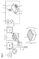
- a target contour 2 of a workpiece 3 is defined by means of a customary CAD system 1.
- the target contour 2 is fed to a CAM system 4.
- the CAM system 4 is programmed with a computer program 5.
- the CAM system 4 is basically a computing device.
- the terms CAM system 4 and computing device are therefore used synonymously.
- the computer program 5 comprises machine code 6 which can be processed by the CAM system 4.
- the execution of the machine code 6 by the CAM system 4 causes the CAM system 4 to perform a determination process, which will be described later.
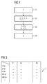
- the CAM system 4 As part of the execution of the computer program 5 takes the CAM system 4 as shown in FIG. 2 in a step S1 from the CAD system 1, the target contour 2 against. Furthermore, the CAM system 4 in a step S2 dynamic parameters D of a processing machine 7 (see FIG. 1 ) known.
- the dynamic parameters D are dynamic parameters of the processing machine 7, which must be maintained during the processing of the workpiece 3 by the tool 9. It can be in the dynamics parameters D as shown in FIG. 3 for example, a maximum possible speed vmax of an axis A1 to An of the processing machine 7, a maximum possible acceleration amax of an axis A1 to An of the processing machine 7, a maximum possible jerk rmax an axis axis A1 to An of the processing machine 7, a maximum torque Mmax of Drive an axis axis A1 to An the processing machine 7, a maximum current increase ⁇ Imax (in A / s) of the respective drive, etc. act.
- the dynamic parameters D can be as shown in FIG. 3 individually defined for each axis A1 to An of the processing machine 7.
- the mentioned dynamics parameters D are related to the state in which the workpiece 3 is machined by the tool 9, in which therefore, for example, during a machining operation, a milling cutter (as an example of a tool 9 suitable for this purpose) is in engagement with the workpiece 3.
- the dynamics parameters D are not related to the state in which the tool 9 is moved relative to the workpiece 3, but the workpiece 3 is not processed by the tool 9 during this movement.
- further machine-specific dynamic parameters D 'are defined In this case, the machine-specific dynamic parameters D 'are related to the state in which the workpiece 3 is not processed by the tool 9.
- the further machine-specific dynamic parameters D ' can also be supplied to the CAM system 4 and taken into account analogously to the machine-specific dynamic parameters D.
- the CAM system 4 determines a web B (or the corresponding parts program) for the processing machine 7.
- the processing machine 7 can, for example be designed as a processing machine, as a production machine or as a robot.
- the path B corresponds to the path to be traveled by the tool 9 of the processing machine 7 relative to the workpiece 3 to be machined by the tool 9.
- the traversing of the web B by the tool 9 causes the machining of the workpiece 3 caused thereby by the tool 9 to transfer the workpiece 3 into the target contour 2.
- the CAM system 4 is also familiar with an initial contour 10 of the workpiece 3, that is to say that contour which the workpiece 3 has before being processed by the tool 9.
- the CAM system 4 therefore determines the web B in step S3, starting from the initial contour 10.
- the initial contour 10 can be explicitly specified to the CAM system 4 or known to the CAM system 4 due to other circumstances.
- the processing is associated with a material removal.
- the initial contour 10 is a maximum contour.
- the machining is associated with a material structure.
- the initial contour 10 is a minimal contour.
- the determination of the web B takes place - of course - such that the processing of the workpiece 3 effected thereby by the tool 9 transfers the workpiece 3 into the target contour 2.
- the CAM system 4 takes into account in step S3, ie in the determination of the web B, not only the target contour 2, but also the machine-specific dynamic parameters D of the processing machine 7 and possibly also the other machine-specific dynamic parameters D '.
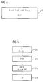
- the CAM system 4 determines the web B in such a way that the determined web B, taking into account the machine-specific dynamic parameters D of the processing machine 7, is optimal in accordance with an evaluation criterion K.
- the evaluation criterion K for example, according to FIG. 4 the shutdown the train B required time T go.
- the energy E required for tracing the web B and the associated processing can be included in the evaluation criterion K.
- a technology criterion TK dependent on the machining of the workpiece 3 by the tool 9 can be included in the evaluation criterion K.
- the technology criterion TK can be, for example, as constant as possible cutting performance, minimum wear of the tool 9, minimal wear of the processing machine 7, etc.
- the individual criteria that are used to determine the value W can be weighted with corresponding weighting factors k1, k2, etc. Individual ones of the weighting factors k1, k2, etc. may have the value 0. However, at least one of the weighting factors k1, k2, etc. must have a value other than 0.
- the CAM system 4 for implementing the step S3 according to FIG. 5 in a step S11, the web B initially as a provisional orbit B begin.
- the CAM system 4 determines a value W for the evaluation criterion K in a step S12.
- the CAM system 4 varies the set path B. The variation occurs such that the value W of the evaluation criterion K is an optimum Assumes value, in particular becomes maximum or minimum.
- the given machine-specific dynamic parameters D taken into account so that they are always adhered to.
- the CAM system 4 takes over the path B varied in step S13 as the final path B.
- the optimization may result in track B not being defined to be - as in FIG FIG. 1 shown in solid lines - is moved along the workpiece 3, but so that they - as in FIG. 1 shown in parentheses and dashed lines - traversed across the workpiece 3.
- the two representations in FIG. 1 are not meant to be limiting. They are merely intended to represent that the railway B, taking into account the dynamic parameter D is determined, may look different than the web B, which would be determined without consideration of the dynamics parameter D.
- control-specific parameters P of the numerical control 8 can be supplied to the CAM system 4, for example, in step S2 together with the dynamic parameters D.
- the CAM system 4 additionally to receive at least one processing parameter P 'which qualitatively or quantitatively characterizes the processing of the workpiece 3 by the tool 9.
- the CAM system 4 as the processing parameter P ', the material of the tool 9 and / or the material of the workpiece 3 can be specified.
- the CAM system 4 additionally takes into account the processing parameter P 'as part of the determination of the web B.
- the processing parameter P ' can be supplied to the CAM system 4, for example, in step S2 together with the dynamic parameters D.
- the CAM system 4 can track the dynamic parameters D of the processing machine 7 as a function of the processing of the workpiece 3 caused by the traversing of the web B, and in the course of determining the web B the dynamic machine-specific dynamic parameters D of the processing machine 7 considered. This results in a coupled system in which the dynamic parameters D influence the path B and the path B or at least the location in turn the dynamic parameters D.
- a dynamic determination of the dynamic parameters D is particularly useful when an axis A1 to An acts on the workpiece 3 and as dynamic parameters D for this axis A1 to An not only the maximum possible acceleration amax and / or the maximum possible jerk rmax are specified but also the maximum torque Mmax of the associated drive and / or the maximum current increase ⁇ Imax of this drive.
- a dynamic determination of the dynamic parameters D is particularly useful if - for example due to the kinematics of the processing machine 7 - the maximum possible speed vmax, the maximum possible acceleration amax and / or the maximum possible jerk rmax of the respective position of the tool 9 relative to the workpiece 3 depend. In all these cases, the CAM system 4 as shown in FIG FIG.
- the CAM system 4 can determine whether, for example, the acceleration of the workpiece 3 is limited by the maximum permissible moment Mmax or the maximum permissible acceleration amax at a certain stage of the machining, and take this fact into account accordingly.
- the orbital parameter s essentially indicates the path traveled from the beginning of the path B to the respective position on the path B.
- the clamping A of the workpiece 3 in a workpiece holder 11 is fixed. In other cases, it is possible to clamp the workpiece 3 in different ways in the workpiece holder 11. In such cases, in the case of a first setup A, a first web B be optimal, in the case of a second setup A a second path B. In this case, it is possible that the CAM system 4 for the various possible setups A each determines the associated path B and compared with each other. In this case, the CAM system 4 additionally determines, in a step S 4, the clamping A whose associated path B is better evaluated and outputs this clamping A, for example to an operator 12.
- the CAM system 4 is combined with the numerical controller 8 to a unit. This is in FIG. 1 is shown by a dashed outline containing both the CAM system 4 and the numerical control 8. However, it is also possible that the CAM system 4 is a unit separate from the numerical controller 8. This is in FIG. 1 indicated by a dot-dash line within the dashed frame.
- the web B (or equivalently a part program) can be determined in a simple manner, which in addition to effecting the desired machining of the workpiece 3 an optimized operation of the processing machine 7 leads.
- the dynamically available dynamics of the processing machine 7 is used optimally. The optimization may be directed to the required machining time, machining conditions, wear and other as needed.
- the productivity and durability of the tool 9 and the processing machine 7 can be increased.
Landscapes
- Engineering & Computer Science (AREA)
- Physics & Mathematics (AREA)
- Human Computer Interaction (AREA)
- Manufacturing & Machinery (AREA)
- General Physics & Mathematics (AREA)
- Automation & Control Theory (AREA)
- Geometry (AREA)
- Numerical Control (AREA)
Priority Applications (1)
| Application Number | Priority Date | Filing Date | Title |
|---|---|---|---|
| EP16194200.8A EP3309635A1 (fr) | 2016-10-17 | 2016-10-17 | Détermination d'un programme de pièce optimisé pour une machine de traitement respective |
Applications Claiming Priority (1)
| Application Number | Priority Date | Filing Date | Title |
|---|---|---|---|
| EP16194200.8A EP3309635A1 (fr) | 2016-10-17 | 2016-10-17 | Détermination d'un programme de pièce optimisé pour une machine de traitement respective |
Publications (1)
| Publication Number | Publication Date |
|---|---|
| EP3309635A1 true EP3309635A1 (fr) | 2018-04-18 |
Family
ID=57137981
Family Applications (1)
| Application Number | Title | Priority Date | Filing Date |
|---|---|---|---|
| EP16194200.8A Withdrawn EP3309635A1 (fr) | 2016-10-17 | 2016-10-17 | Détermination d'un programme de pièce optimisé pour une machine de traitement respective |
Country Status (1)
| Country | Link |
|---|---|
| EP (1) | EP3309635A1 (fr) |
Cited By (4)
| Publication number | Priority date | Publication date | Assignee | Title |
|---|---|---|---|---|
| CN113032859A (zh) * | 2021-03-30 | 2021-06-25 | 南通苏尼康自动化技术有限公司 | 一种基于dxf图纸导入的通用旋压机械加工程序生成方法 |
| CN115922470A (zh) * | 2022-12-05 | 2023-04-07 | 华海清科股份有限公司 | 一种基板磨削方法 |
| CN116034322A (zh) * | 2020-08-10 | 2023-04-28 | 西门子股份公司 | 机床的运行方法、计算机程序产品、控制单元和机床 |
| EP4682656A1 (fr) * | 2024-07-15 | 2026-01-21 | Carl Zeiss SMT GmbH | Dispositif pour modifier la forme d'une surface d'un objet |
Citations (6)
| Publication number | Priority date | Publication date | Assignee | Title |
|---|---|---|---|---|
| EP0798616A2 (fr) * | 1996-03-29 | 1997-10-01 | Toyota Jidosha Kabushiki Kaisha | Procédé de génération de points d'une trajectoire de coupe en fonction des conditions de production sélectionnées pour une ébauche |
| US20100138018A1 (en) * | 2008-11-24 | 2010-06-03 | Siemens Aktiengesellschaft | Method for producing a parts program |
| DE102009015934A1 (de) * | 2009-04-02 | 2010-10-07 | Dmg Electronics Gmbh | Verfahren und Vorrichtung zum Erzeugen von Steuerdaten zum Steuern eines Werkzeugs an einer Werkzeugmaschine |
| WO2016065492A1 (fr) * | 2014-10-31 | 2016-05-06 | Cloudbased Industry 4.0 Technologies Ag | Procédé informatisé d'analyse de composants d'une pièce usinée par au moins une machine à cnc |
| WO2016065491A1 (fr) * | 2014-10-31 | 2016-05-06 | Cloudbased Industry 4.0 Technologies Ag | Procédé d'optimisation de la productivité d'un processus d'usinage d'une machine à cnc |
| EP3067762A1 (fr) * | 2015-03-10 | 2016-09-14 | Siemens Aktiengesellschaft | Procédé de détermination d'une position de serrage optimale d'une pièce dans une machine de traitement |
-
2016
- 2016-10-17 EP EP16194200.8A patent/EP3309635A1/fr not_active Withdrawn
Patent Citations (6)
| Publication number | Priority date | Publication date | Assignee | Title |
|---|---|---|---|---|
| EP0798616A2 (fr) * | 1996-03-29 | 1997-10-01 | Toyota Jidosha Kabushiki Kaisha | Procédé de génération de points d'une trajectoire de coupe en fonction des conditions de production sélectionnées pour une ébauche |
| US20100138018A1 (en) * | 2008-11-24 | 2010-06-03 | Siemens Aktiengesellschaft | Method for producing a parts program |
| DE102009015934A1 (de) * | 2009-04-02 | 2010-10-07 | Dmg Electronics Gmbh | Verfahren und Vorrichtung zum Erzeugen von Steuerdaten zum Steuern eines Werkzeugs an einer Werkzeugmaschine |
| WO2016065492A1 (fr) * | 2014-10-31 | 2016-05-06 | Cloudbased Industry 4.0 Technologies Ag | Procédé informatisé d'analyse de composants d'une pièce usinée par au moins une machine à cnc |
| WO2016065491A1 (fr) * | 2014-10-31 | 2016-05-06 | Cloudbased Industry 4.0 Technologies Ag | Procédé d'optimisation de la productivité d'un processus d'usinage d'une machine à cnc |
| EP3067762A1 (fr) * | 2015-03-10 | 2016-09-14 | Siemens Aktiengesellschaft | Procédé de détermination d'une position de serrage optimale d'une pièce dans une machine de traitement |
Non-Patent Citations (1)
| Title |
|---|
| LUIGI BIAGIOTTI, CLAUDIO MELCHIORRI: "Trajectory Planning for Automatic Machines and Robots", 3 November 2008, SPRINGER-VERLAG, BERLIN HEIDELBERG, ISBN: 978-3-540-85628-3, pages: 208 - 244, XP002768850 * |
Cited By (7)
| Publication number | Priority date | Publication date | Assignee | Title |
|---|---|---|---|---|
| CN116034322A (zh) * | 2020-08-10 | 2023-04-28 | 西门子股份公司 | 机床的运行方法、计算机程序产品、控制单元和机床 |
| US12443163B2 (en) | 2020-08-10 | 2025-10-14 | Siemens Aktiengesellschaft | Operating method for a machine tool, computer program product, control unit and machine tool |
| CN113032859A (zh) * | 2021-03-30 | 2021-06-25 | 南通苏尼康自动化技术有限公司 | 一种基于dxf图纸导入的通用旋压机械加工程序生成方法 |
| CN113032859B (zh) * | 2021-03-30 | 2024-06-11 | 南通穆伦伯格科技有限公司 | 一种基于dxf图纸导入的通用旋压机械加工程序生成方法 |
| CN115922470A (zh) * | 2022-12-05 | 2023-04-07 | 华海清科股份有限公司 | 一种基板磨削方法 |
| CN115922470B (zh) * | 2022-12-05 | 2024-08-20 | 华海清科股份有限公司 | 一种基板磨削方法 |
| EP4682656A1 (fr) * | 2024-07-15 | 2026-01-21 | Carl Zeiss SMT GmbH | Dispositif pour modifier la forme d'une surface d'un objet |
Similar Documents
| Publication | Publication Date | Title |
|---|---|---|
| DE102009007437B4 (de) | Reitstock-Regelungsvorrichtung | |
| EP2174748B1 (fr) | Machine-outil et procédé d'amortissement d'oscillations d'un élément de machine d'une machine-outil | |
| EP2189861B1 (fr) | Procédé de fabrication d'un programme de pièce | |
| EP3220223B1 (fr) | Procede d'usinage d'une piece a usiner sur une machine d'usinage avec temps d'usinage optimise | |
| EP2008753B1 (fr) | Machine-outil et procédé destinés au traitement d'une pièce à usiner | |
| DE102015111964B4 (de) | Servomotoren-Steuersystem, das die Bearbeitungspräzision mehrerer Achsen verbessert | |
| DE102014008658A1 (de) | Numerische Werkzeugmaschinensteuerung zum Bohren | |
| EP3309635A1 (fr) | Détermination d'un programme de pièce optimisé pour une machine de traitement respective | |
| EP2192465B1 (fr) | Réglage d'un entraînement asservi doté d'une détermination dynamique de la dynamique de l'axe conducteur | |
| DE102005047466B3 (de) | Verfahren zur Optimierung des Bearbeitungsprozesses bei einer Maschine | |
| EP3585551A1 (fr) | Procédé de fonctionnement d'une installation de traitement de pièces, et installation de traitement de pièces | |
| EP2162806A1 (fr) | Machine-outil à commande numérique | |
| EP4147102B1 (fr) | Fonctionnement d'une machine-outil au moins à deux axes | |
| DE102017000064B4 (de) | Numerische Steuerung mit einer Schnittsteuerfunktion durch Revolverdrehung | |
| DE102016000409B4 (de) | Numerische Steuerung, die ein Maschinenwerkzeug auf der Basis von Schälanweisungen steuert | |
| EP0743579A2 (fr) | Procédé de commande d'une machine outil à commande numérique ou d'un robot | |
| DE10027526B4 (de) | Verfahren zur Fräsbearbeitung eines Werkstücks mit einem Fräswerkzeug, und daran angepaßte Fräseinrichtung | |
| EP3708297A1 (fr) | Commande optimisée d'un amortisseur de vibrations actif | |
| EP3625628B1 (fr) | Structure de régulateur pour entraînement mixte direct / indirect d'un élément de machine | |
| EP2533927B1 (fr) | Machine à estamper et/ou à grignoter et procédé de commande d'une machine à estamper et/ou à grignoter | |
| DE102018004924B4 (de) | Steuerung | |
| EP2832485A2 (fr) | Machine à tailler les engrenages | |
| EP4479806B1 (fr) | Compensation de la déflexion d'outil par ajustement dynamique de la géométrie d'outil | |
| EP3176658A1 (fr) | Unite de commande et procede de commande d'une machine-outil et son utilisation | |
| EP3833509B1 (fr) | Élimination de vibrations définie par l'utilisateur |
Legal Events
| Date | Code | Title | Description |
|---|---|---|---|
| PUAI | Public reference made under article 153(3) epc to a published international application that has entered the european phase |
Free format text: ORIGINAL CODE: 0009012 |
|
| AK | Designated contracting states |
Kind code of ref document: A1 Designated state(s): AL AT BE BG CH CY CZ DE DK EE ES FI FR GB GR HR HU IE IS IT LI LT LU LV MC MK MT NL NO PL PT RO RS SE SI SK SM TR |
|
| AX | Request for extension of the european patent |
Extension state: BA ME |
|
| STAA | Information on the status of an ep patent application or granted ep patent |
Free format text: STATUS: THE APPLICATION IS DEEMED TO BE WITHDRAWN |
|
| 18D | Application deemed to be withdrawn |
Effective date: 20181019 |