EP0743589A2 - Méthode interactive de génération d'image et appareil interactif - Google Patents
Méthode interactive de génération d'image et appareil interactif Download PDFInfo
- Publication number
- EP0743589A2 EP0743589A2 EP96303015A EP96303015A EP0743589A2 EP 0743589 A2 EP0743589 A2 EP 0743589A2 EP 96303015 A EP96303015 A EP 96303015A EP 96303015 A EP96303015 A EP 96303015A EP 0743589 A2 EP0743589 A2 EP 0743589A2
- Authority
- EP
- European Patent Office
- Prior art keywords
- operator
- point
- identifying
- instruction
- displayed
- Prior art date
- Legal status (The legal status is an assumption and is not a legal conclusion. Google has not performed a legal analysis and makes no representation as to the accuracy of the status listed.)
- Granted
Links
Images








Classifications
-
- G—PHYSICS
- G06—COMPUTING OR CALCULATING; COUNTING
- G06F—ELECTRIC DIGITAL DATA PROCESSING
- G06F3/00—Input arrangements for transferring data to be processed into a form capable of being handled by the computer; Output arrangements for transferring data from processing unit to output unit, e.g. interface arrangements
- G06F3/01—Input arrangements or combined input and output arrangements for interaction between user and computer
- G06F3/016—Input arrangements with force or tactile feedback as computer generated output to the user
-
- G—PHYSICS
- G06—COMPUTING OR CALCULATING; COUNTING
- G06F—ELECTRIC DIGITAL DATA PROCESSING
- G06F3/00—Input arrangements for transferring data to be processed into a form capable of being handled by the computer; Output arrangements for transferring data from processing unit to output unit, e.g. interface arrangements
- G06F3/01—Input arrangements or combined input and output arrangements for interaction between user and computer
- G06F3/011—Arrangements for interaction with the human body, e.g. for user immersion in virtual reality
-
- G—PHYSICS
- G06—COMPUTING OR CALCULATING; COUNTING
- G06F—ELECTRIC DIGITAL DATA PROCESSING
- G06F3/00—Input arrangements for transferring data to be processed into a form capable of being handled by the computer; Output arrangements for transferring data from processing unit to output unit, e.g. interface arrangements
- G06F3/16—Sound input; Sound output
Definitions
- This invention relates to an image generation method and apparatus. More particularly, the invention relates to an interactive image generation method and apparatus in which a computer interprets geometrical graphic data relating to fonts, plane figures, stereoscopic shapes and the like, attribute data relating to colors, patterns and the like, and scene description data, such as data relating to illumination, data relating to projection, and the like, and in which respective scene data are changed in accordance with interactive operation instructions of the operator, new images are calculated and generated with a short time interval of at least a few frames per second, and the displayed picture surface is sequentially updated.
- the operation of designating the target figure is generally performed by trial and error.
- a prompt figure selection operation can be performed by a direct action of looking at the figure to be selected without requiring an indirect manual instruction operation
- the present invention relates to an image generation method comprising the steps of obtaining the position of a visual point of an operator, identifying a direction or line of sight along which the operator is looking, identifying a displayed figure intersected by that direction or line of sight, calculating the coordinates of a point where that direction intersects the displayed figure, registering the position obtained in the calculating step as an operating point, performing transformation for information relating to respective coordinates of the displayed figure identified in the object identifying step and the operating point registered in the registering step making the operating point an origin for coordinate transformation, generating an image of a figure based on the information transformed in the transformation step making the position of the visual point obtained in the measuring step an origin for projection, and displaying the image generated in the generating step.
- the present invention relates to an image generation apparatus comprising visual-point-position measuring means for obtaining the position of a visual point of an operator, visual-point-direction measuring means for identifying a direction or a line of sight along which the operator is looking, object determination means for identifying a displayed figure crossed by that direction or line of sight, position determination means for calculating the coordinates of a point where the direction or line of sight intersects the displayed figure, operating-point registration means for registering the position obtained by the position determination means, figure-coordinate tranformation means for performing transformation for information relating to respective coordinates of the displayed figure determined by the object determination means, and the operating point registered by the operating-point registration means, making the operating point an origin for coordinate transformation, image generation means for generating an image of a figure based on the information transformed by the figure-coordinate transformation means making the position of the visual point obtained by the visual-point-position measuring means an origin for projection, and display means for displaying the image generated by the image generation means.
- the figure to be selected when the operator selects a figure whose position, posture and other attribute are to be changed, from among a plurality of figures displayed on the picture surface of a display device, the figure to be selected can be designated by means of the direction of the operator's line of sight.
- the position and the posture of the operator's head, and the direction of the line of sight of the operator's dominant eye are measured and input using a position/posture detection device mounted on the operator's head and an eyeball-motion detection device mounted in the vicinity of the operator's dominant eye.
- the position of the start point and the direction of the line of sight of the dominant eye relative to the picture surface of an image display device are calculated based on the above-described information.
- the geometrical information of the position of the start point is subjected to coordinate transformation into the coordinate system of a three-dimensional space which defines displayed figures.
- the bending angles of respective finger joints of the operator's hand are measured by finger-joint-bending-angle detection devices mounted on a hand of the operator, and it is determined if a group of bending angles corresponds to a gesture predetermined as a signal indicating execution of instruction to select a figure, for example, a combination of angles for providing a state of "clench the fist" in the present embodiment.
- a flag indicating a state of selecting a figure is raised, and the calculated position of the point being looked at is recorded as an operating origin for an operation in a coordinate system having a group of the coordinates of vertices constituting the figure unit indicated by the line of sight.
- a three-dimensional position/posture measuring device mounted on the hand records the position and the posture of the hand at that time as an initial position of an operation.
- the position and the posture of the hand are measured by the three-dimensional position/posture measuring device mounted on the hand, the difference between the measured position/posture and the position/posture at the initial position of the operation is obtained, and parallel movement transformation and rotation transformation (taking the difference as the amount of transformation) are performed on the coordinates of vertices constituting the selected figure, and the operating origin, making the operating origin an origin for coordinate transformation.
- the image of the entire figure unit is generated making the position of the visual point of the dominant eye an origin of projection based on a perspective projection drawing method, and the image is displayed on the image display device together with a cursor indicating the position of the visual point.
- a gesture determined in advance to be a signal indicating release of the figure selection mode for example, a combination of angles for providing a state of "open the fist" in the present embodiment, is performed. If it is determined that the operator has performed the gesture to release the figure selection mode, the flag indicating the figure selection mode is released.
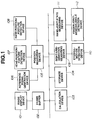
- an image display device 101 displays images for the operator, and comprises a CRT (cathode-ray tube) display device, an LCD (liquid-crystal display) device or the like.
- CRT cathode-ray tube
- LCD liquid-crystal display
- a frame buffer 102 stores image data to be displayed on the image display device 101.
- a calculation device 103 executes processing in accordance with processing procedures stored in a storage device 104 to generate image data, and controls respective devices. Image data generated by the calculation device 103 is stored in the frame buffer 102.
- the storage device 104 stores processing procedures of the calculation device 103 and information necessary for processing, and also provides storage regions for calculation operations required for the processing of the calculation device 103.
- the storage device 104 stores control programs for the flowchart shown in FIG. 5 (to be described later), data relating to figures to be depicted, and data necessary for processing.
- a position measuring device 105 analyzes signals from a head position/posture detection device 107 and signals from a hand position/posture detection device 108, and input information relating to the position and the posture of the operator's head, and the position and the posture of the operator's hand relative to a reference-signal generation device 106 reference.
- the reference-signal generation device 106 generates a signal which serves as reference for the head position/posture detection device 107 and the hand position/posture detection device 108.
- the head position/posture detection device 107 detects the position and the posture of the operator's head, and is fixed to the head using a cap, a band or the like.
- the hand position/posture detection device 108 detects the position and the posture of the operator's hand used for operations, and is fixed to the back of the hand, the wrist or the like using a band, a glove or the like.
- a sight-line-direction measuring device 109 analyzes signals from an eyeball-motion detection device 110, and inputs information relating to the direction of the line of sight relative to the head to the calculation device 103.
- the eyeball-motion detection device 110 detects the direction of the visual line of the eyeball of the operator's dominant eye, and is mounted at a position in front of the dominant eye, where the field of view of the dominant eye in the forward direction is not obstructed, on a spectacle frame or the like.
- a hand-joint-state measuring device 111 analyzes signals from finger-joint-bending-angle detection devices 112, and inputs information relating to the bending angle of each finger joint of the operator's hand to the calculation device 103.
- the finger-joint-bending-angle detection devices 112 are mounted on main portions of respective finger joints of the operator's hand used for operations of the operator using a glove or the like.
- the reference-signal generation device 106 is fixed to an upper portion of the image display device 101.
- the reference-signal generation device 106 may be disposed according to any other method for fixing it relative to the image display device 101.
- the reference-signal generation device 106 may be fixed on a base for fixing the image display device 101.
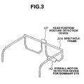
- the head position/posture detection device 107 and the eyeball-motion detection device 110 are fixed to the operator's head using a tool 204 having the shape of a spectacle frame.
- the eyeball-motion detection device 110 is mounted at a position in front of the eyeball of the operator's dominant eye where the field of view in the forward direction is not obstructed, using the tool 204 for fixing/supporting detection devices.
- FIG. 3 illustrates the configuration of the tool 204 for fixing/supporting detection devices.
- FIG. 4 illustrates a tool 205 for mounting finger-joint-bending-angle detection devices.
- the finger-joint-bending-angle detection devices 112 are fixed on main portions of the respective finger joints of the operator's hand 203 using the tool 205, havin the shape of a glove, for mounting finger-joint-bending-angle detection devices.
- the hand position/posture detection device 108 is also fixed to the back of the operator's hand using the mounting tool 205.
- the hand position/posture detection device 108 may be fixed to the wrist of the operator's hand using a strap.
- the other devices are arranged at arbitrary appropriate positions.
- FIG. 5 is a flowchart illustrating the flow of image generation processing in the first embodiment.
- the position measuring device 105 measures the position and the posture of the head position/posture detection device 107 relative to the position and the posture of the reference-signal generation device 106.
- Information relating to the coordinates of the position and the posture of the head position/posture detection device 107 is subjected to coordinate transformation into the coordinate system which defines the displayed figures, to provide information relating to the coordinates of the position and the posture of the operator's head.
- step 502 the position of the visual point of the operator's dominant eye 202 in the coordinate system which defines the figure data is calculated.
- the coordinate values of the position of the visual point of the dominant eye 202 relative to the position and the posture of the head position/posture detection device 107 are stored in advance as offset values, and the position of the visual point of the dominant eye 202 is determined by adding these offset values to the coordinates of the position of the head position/posture detection device 107 obtained in step 501.
- step 503 the direction of the line of sight in the coordinate system which defines the figure data is calculated based on vector information obtained by analyzing a signal from the eyeball-motion detection device 110 by the sight-line-direction measuring device 109 and information relating to the posture of the operator's head obtained in step 501.
- FIG. 6 illustrates the positional relationship among the direction of the operator's line of sight, the image display surface, figures and the like.
- step 504 signals from the finger-joint-bending-angle detection devices 112 mounted on the finger joints of the hand are analyzed by the hand-joint-state measuring device 111, and the bending angles of the respective finger joints are measured.
- step 505 the currently performed gesture is determined from the combination of the bending angles of the respective finger joints.
- step 506 If a figure to be operated is not currently selected in step 506, it is then determined in step 507 if the hand's gesture corresponds to a "clench" of the fist, as if grasping.
- step 507 If the result of the determination in step 507 is affirmative, it is determined that the operator has instructed to select a figure to be operated on, and processing of selecting the figure to be operated on, from step 508 to step 513, is executed.
- step 508 a test of intersection between the line of sight and the displayed figures is performed. In this test of intersection, it is calculated whether or not a point of intersection between a curved surface or a flat surface constituting a figure unit, and a half line indicating the line of sight, is present.
- the data of figure units are stored in a figure-data list, for example, in the form shown in FIG. 7.
- the items of respective figure data in the data list comprise, the identification number of each figure data, the kind of each figure, geometrical data of each figure, and the like.
- step 509 it is determined if an intersecting figure unit is present. If the result of the determination is affirmative, in step 510, the coordinates of the point of intersection between a curved surface or a flat surface constituting the intersecting figure, and the line of sight, are obtained.
- step 511 the figure unit including the point of intersection which is closest to the visual point is registered as the object to be operated on.
- step 512 the point of intersection closest to the visual point is registered as an operating point for coordinate transformation.
- the position/posture measuring device 105 measures the position and the posture of the hand based on a signal from the hand position/posture detection device 108, and the position and the posture at that time are registered as an initial position for an operation.
- step 514 If a figure which is currently selected as an object to be operated on is present in step 506, it is determined in step 514 if the hand's gesture corresponds to "open the fist". If the result of the determination is affirmative, it is determined that the operator has instructed to terminate the operation of selecting the figure, and a state of selecting nothing is provided by releasing the selected figure.
- step 514 If the result of the determination in step 514 is negative, the position and the posture of the hand are measured by the hand position/posture measuring device 108, the reference-signal generation device 106 and the position/posture measuring device 105, and the difference from the initial position registered in step 513 is calculated.
- step 517 the coordinates of vertices of flat surfaces and the coordinates of control points of curved surfaces constituting the figure unit selected and registered as the object to be operated, and the position of the operating point are subjected to parallel movement transformation and rotation movement transformation by the difference in the position and the posture obtained in step 516 making the registered operating origin an origin of coordinate transformation, and the coordinate values are replaced by new coordinate values after transformation.
- step 518 the image of the entire figure unit is generated making the position of the visual point obtained in step 502 an origin of projection according to the perspective drawing projection method, and the generated image is stored in the frame buffer 102.
- the image of a small cross-shaped figure, serving as an index indicating the direction of the line of sight, is generated at the position where the direction of the line of sight intersects the figure unit on the picture surface of the display device. (This index may have any other shape).
- step 519 the image stored in the frame buffer 102 is displayed on the image display device 101.
- step 520 it is determined if an instruction to terminate the image generation processing from the operator is present. If the result of the determination is negative, the processing from step 501 is repeated. If the result of the determination is affirmative, the processing is terminated.
- a figure to be selected as an object to be operated on is indicated according to the direction of the operator's line of sight, and an operation of selecting a figure is executed according to the hand's gesture.
- the operator's voice is recognized, and selection of a figure is executed according to a voice instruction of the operator.
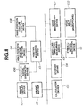
- FIG. 8 The basic configuration of the second embodiment is shown in FIG. 8.
- FIG. 8 is a block diagram illustrating the basic configuration of an interactive image generation apparatus according to the second embodiment.
- the basic configuration of the second embodiment differs from that of the first embodiment in that the finger-joint-bending-angle detection devices 112 and the hand-joint-state measuring device 111 of the first embodiment are removed and, instead, a voice input device 802 and a voice recognition device 801 are provided.
- the voice input device 802 is a device for obtaining a voice signal from the operator, and comprises a microphone or the like.
- the voice recognition device 801 is a device for recognizing a voice instruction of the operator.
- the voice recognition device 801 analyzes a voice signal input from the voice input device 802, and inputs character information indicating the contents of the voice to a calculation device 103.
- the voice input device 802 is disposed at a position where the operator's voice can be easily input.
- a hand position/posture detection device 108 may instead be held in the operator's hand.
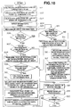
- FIG. 10 is a flowchart illustrating the flow of image generation processing in the second embodiment.
- step 904 a voice signal from the voice input device 802 is input.
- step 905 the voice signal is analyzed and is converted into character-string information indicating the contents of the voice.
- step 907 if the voice's instruction is "selection of a figure", it is determined that the selection of a figure has been instructed.
- the voice instruction which is registered in advance in voice recognition device 801 for this purpose may be any other instruction than "selection of a figure”).
- step 914 if the contents of the voice instruction indicate "release of selection”, it is detemined that release of selection of the figure has been instructed. Again, the voice instruction which is registered in advance for this purpose may be any other instruction than "release of selection”.
- a figure to be selected as an object to be operated on is indicated according to the direction of the line of sight, and an operation of selecting a figure is executed according to the hand's gesture.
- the operator checks the state of a push button switch held in his or her hand, and selection of a figure is executed when the operator depresses the push button switch.
- FIG. 11 The basic configuration of the third embodiment is shown in FIG. 11.
- the basic configuration of the third embodiment differs from that of the first embodiment in that the finger-joing-bending-angle detection devices 112 and the hand-joint-state measuring device 111 of the first embodiment are removed and, instead, a push button switch 1101 is provided.
- the operator inputs one of two states, i.e., an on-state and an off-state, to a calculation device 103 by operating the push button switch 1101.
- FIG. 12 is a schematic diagram illustrating detection devices constituting the interactive image generation apparatus of the third embodiment, and differs from the corresponding illustration of the first embodiment in the respects just mentioned.
- the push button switch 1101 and a hand position/posture detection device 108 are fixed on a grip 1201 grasped by the operator.
- the push button switc 1101 and the hand position/posture detection device 108 may be held separately by the right hand and the left hand.
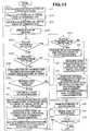
- FIG. 14 is a flowchart illustrating the flow of image generation processing in the third embodiment.
- step 1404 the state of the push button switch 1101 is checked.
- step 1407 if the state of the push button switch 1101 has changed from the off-state to the on-state, it is determined that selection of a figure has been instructed.
- step 1414 if the state of the push button switch 1101 has changed from the on-state to the off-state, it is determined that release of selection of a figure has been instructed.
- the direction of the operator's line of sight is measured using the eyeball-motion detection device 110 and the sight-line-direction measuring device 109.
- the forward direction of the head measured by the head position/posture detection device 107, the position measuring device 105 and the reference-signal generation device 106 is used as alternate information for the direction of the line of sight.
- FIG. 15 The basic configuration of the fourth embodiment is shown in FIG. 15.
- the basic configuration of the fourth embodiment differs from that of the first embodiment in that the eyeball-motion detection device 110 and the sight-line-direction measuring device of the first embodiment are removed.
- FIG. 16 illustrates the arrangement of detection devices in the fourth embodiment, which differs from the arrangement of the devices in the previous embodiments in the manner just stated.
- FIG. 5 The flow of image generation/display processing in the fourth embodiment is represented by FIG. 5, as in the first embodiment.
- the details of the processing in all steps except step 503 are the same as in the processing of the first embodiment.
- step 503 of the fourth embodiment the approximation is made that the line of sight of the dominant eye is always directed in the forward direction of the head, and the vector of the foward direction derived from the posture of the head obtained in step 501 is used for the sight-line vector.
- the operator when, in an interactive image generation apparatus, the operator selects a figure whose position, posture and other attribute are to be changed from among a plurality of figures defined in a three-dimensional virtual space and displayed on the picture surface of a display device, the figure to be selected can be instructed by the direction of the operator's line of sight.
- a prompt figure selection operation can be performed without requiring an indirect manual instruction operation.
- One aspect of the present invention provides a user interface for a computer to allow a user to select an object in a virtual world and to carry out predetermined operations on the object once selected.
- the predetermined operations can comprise outputting data to an output device such as a printer or the modification of a display can be caused.
Landscapes
- Engineering & Computer Science (AREA)
- General Engineering & Computer Science (AREA)
- Theoretical Computer Science (AREA)
- Human Computer Interaction (AREA)
- Physics & Mathematics (AREA)
- General Physics & Mathematics (AREA)
- Health & Medical Sciences (AREA)
- Audiology, Speech & Language Pathology (AREA)
- General Health & Medical Sciences (AREA)
- User Interface Of Digital Computer (AREA)
- Digital Computer Display Output (AREA)
- Position Input By Displaying (AREA)
- Processing Or Creating Images (AREA)
Applications Claiming Priority (3)
| Application Number | Priority Date | Filing Date | Title |
|---|---|---|---|
| JP115746/95 | 1995-05-15 | ||
| JP11574695 | 1995-05-15 | ||
| JP11574695A JP4272711B2 (ja) | 1995-05-15 | 1995-05-15 | 画像生成方法及び装置 |
Publications (3)
| Publication Number | Publication Date |
|---|---|
| EP0743589A2 true EP0743589A2 (fr) | 1996-11-20 |
| EP0743589A3 EP0743589A3 (fr) | 1997-11-12 |
| EP0743589B1 EP0743589B1 (fr) | 2002-09-04 |
Family
ID=14670036
Family Applications (1)
| Application Number | Title | Priority Date | Filing Date |
|---|---|---|---|
| EP96303015A Expired - Lifetime EP0743589B1 (fr) | 1995-05-15 | 1996-04-30 | Méthode interactive de génération d'image et appareil interactif |
Country Status (4)
| Country | Link |
|---|---|
| US (1) | US6437794B1 (fr) |
| EP (1) | EP0743589B1 (fr) |
| JP (1) | JP4272711B2 (fr) |
| DE (1) | DE69623385T2 (fr) |
Cited By (3)
| Publication number | Priority date | Publication date | Assignee | Title |
|---|---|---|---|---|
| EP0845737A3 (fr) * | 1996-11-29 | 1998-06-10 | Canon Kabushiki Kaisha | Méthode et appareil d'affichage d'image |
| EP0903661A1 (fr) * | 1997-08-27 | 1999-03-24 | Canon Kabushiki Kaisha | Appareil et procédé d'entrée de données par détection de la direction du regard |
| CN102012778A (zh) * | 2009-09-04 | 2011-04-13 | 索尼公司 | 显示控制设备、显示控制方法以及显示控制程序 |
Families Citing this family (17)
| Publication number | Priority date | Publication date | Assignee | Title |
|---|---|---|---|---|
| JP2000163196A (ja) * | 1998-09-25 | 2000-06-16 | Sanyo Electric Co Ltd | ジェスチャ認識装置及びジェスチャ認識機能を有する指示認識装置 |
| GB2350005B (en) * | 1999-03-17 | 2003-01-08 | Canon Kk | Image processing apparatus |
| US6825945B1 (en) * | 1999-05-25 | 2004-11-30 | Silverbrook Research Pty Ltd | Method and system for delivery of a brochure |
| US6931596B2 (en) * | 2001-03-05 | 2005-08-16 | Koninklijke Philips Electronics N.V. | Automatic positioning of display depending upon the viewer's location |
| US7295181B2 (en) * | 2001-09-06 | 2007-11-13 | Gunilla Alsio | Data input device |
| US11033821B2 (en) | 2003-09-02 | 2021-06-15 | Jeffrey D. Mullen | Systems and methods for location based games and employment of the same on location enabled devices |
| DK2202609T3 (en) * | 2004-06-18 | 2016-04-25 | Tobii Ab | Eye control of computer equipment |
| US20100295782A1 (en) | 2009-05-21 | 2010-11-25 | Yehuda Binder | System and method for control based on face ore hand gesture detection |
| US8392853B2 (en) * | 2009-07-17 | 2013-03-05 | Wxanalyst, Ltd. | Transparent interface used to independently manipulate and interrogate N-dimensional focus objects in virtual and real visualization systems |
| JP2011028366A (ja) * | 2009-07-22 | 2011-02-10 | Sony Corp | 操作制御装置および操作制御方法 |
| CN101916338B (zh) * | 2010-09-08 | 2012-05-23 | 浙江大学 | 一种自适应的视点平滑滤波数据处理方法 |
| US9292089B1 (en) * | 2011-08-24 | 2016-03-22 | Amazon Technologies, Inc. | Gestural object selection |
| US9563805B2 (en) * | 2014-09-02 | 2017-02-07 | Hong Kong Baptist University | Method and apparatus for eye gaze tracking |
| US9672747B2 (en) | 2015-06-15 | 2017-06-06 | WxOps, Inc. | Common operating environment for aircraft operations |
| JP2018101019A (ja) * | 2016-12-19 | 2018-06-28 | セイコーエプソン株式会社 | 表示装置及び表示装置の制御方法 |
| JP6342038B1 (ja) * | 2017-05-26 | 2018-06-13 | 株式会社コロプラ | 仮想空間を提供するためのプログラム、当該プログラムを実行するための情報処理装置、および仮想空間を提供するための方法 |
| DE102017220529B4 (de) * | 2017-11-17 | 2025-09-04 | Siemens Healthineers Ag | Verfahren zur Bedienung einer Blendeneinrichtung einer Röntgeneinrichtung und Röntgeneinrichtung |
Family Cites Families (14)
| Publication number | Priority date | Publication date | Assignee | Title |
|---|---|---|---|---|
| JPS59139433A (ja) * | 1983-01-28 | 1984-08-10 | Hitachi Ltd | 情報処理装置 |
| US4682159A (en) * | 1984-06-20 | 1987-07-21 | Personics Corporation | Apparatus and method for controlling a cursor on a computer display |
| GB2173079B (en) * | 1985-03-29 | 1988-05-18 | Ferranti Plc | Cursor display control apparatus |
| US4812829A (en) * | 1986-05-17 | 1989-03-14 | Hitachi, Ltd. | Three-dimensional display device and method for pointing displayed three-dimensional image |
| JPH02177766A (ja) | 1988-12-28 | 1990-07-10 | Canon Inc | 2値画像の階層的符号化方式 |
| CA2077173C (fr) * | 1991-11-22 | 2003-04-22 | Michael Chen | Methode et appareil de manipulation directe d'objets tridimensionnels sur un ecran d'ordinateur |
| WO1993014454A1 (fr) | 1992-01-10 | 1993-07-22 | Foster-Miller, Inc. | Interface de donnees integree a commande sensorielle |
| JP3199130B2 (ja) * | 1992-03-31 | 2001-08-13 | パイオニア株式会社 | 3次元座標入力装置 |
| JPH05346957A (ja) * | 1992-04-17 | 1993-12-27 | Hitachi Ltd | 形状特徴量提示装置および方法 |
| US5396590A (en) * | 1992-09-17 | 1995-03-07 | Apple Computer, Inc. | Non-modal method and apparatus for manipulating graphical objects |
| US5590062A (en) * | 1993-07-02 | 1996-12-31 | Matsushita Electric Industrial Co., Ltd. | Simulator for producing various living environments mainly for visual perception |
| JPH0749744A (ja) | 1993-08-04 | 1995-02-21 | Pioneer Electron Corp | 頭部搭載型表示入力装置 |
| US5977935A (en) * | 1993-08-12 | 1999-11-02 | Seiko Epson Corporation | Head-mounted image display device and data processing apparatus including the same |
| US5481622A (en) * | 1994-03-01 | 1996-01-02 | Rensselaer Polytechnic Institute | Eye tracking apparatus and method employing grayscale threshold values |
-
1995
- 1995-05-15 JP JP11574695A patent/JP4272711B2/ja not_active Expired - Fee Related
-
1996
- 1996-04-30 US US08/640,081 patent/US6437794B1/en not_active Expired - Lifetime
- 1996-04-30 EP EP96303015A patent/EP0743589B1/fr not_active Expired - Lifetime
- 1996-04-30 DE DE69623385T patent/DE69623385T2/de not_active Expired - Lifetime
Cited By (5)
| Publication number | Priority date | Publication date | Assignee | Title |
|---|---|---|---|---|
| EP0845737A3 (fr) * | 1996-11-29 | 1998-06-10 | Canon Kabushiki Kaisha | Méthode et appareil d'affichage d'image |
| US6157382A (en) * | 1996-11-29 | 2000-12-05 | Canon Kabushiki Kaisha | Image display method and apparatus therefor |
| EP0903661A1 (fr) * | 1997-08-27 | 1999-03-24 | Canon Kabushiki Kaisha | Appareil et procédé d'entrée de données par détection de la direction du regard |
| US6426740B1 (en) | 1997-08-27 | 2002-07-30 | Canon Kabushiki Kaisha | Visual-axis entry transmission apparatus and method therefor |
| CN102012778A (zh) * | 2009-09-04 | 2011-04-13 | 索尼公司 | 显示控制设备、显示控制方法以及显示控制程序 |
Also Published As
| Publication number | Publication date |
|---|---|
| EP0743589A3 (fr) | 1997-11-12 |
| US6437794B1 (en) | 2002-08-20 |
| DE69623385T2 (de) | 2003-05-22 |
| DE69623385D1 (de) | 2002-10-10 |
| JP4272711B2 (ja) | 2009-06-03 |
| EP0743589B1 (fr) | 2002-09-04 |
| JPH08314621A (ja) | 1996-11-29 |
Similar Documents
| Publication | Publication Date | Title |
|---|---|---|
| EP0743589B1 (fr) | Méthode interactive de génération d'image et appareil interactif | |
| US7353081B2 (en) | Method and a system for programming an industrial robot | |
| JP6116064B2 (ja) | 車両インターフェース用ジェスチャ基準制御システム | |
| EP3283938B1 (fr) | Interface gestuelle | |
| EP0587138A2 (fr) | Dispositif d'interface humaine tri-dimensionnelle utilisant la reconnaissance de mouvements à l'aide d'un traitement dynamique d'images | |
| JPH1051711A (ja) | 3次元仮想物体表示装置および方法 | |
| US20050174361A1 (en) | Image processing method and apparatus | |
| WO2000002187A1 (fr) | Interface utilisateur stereoscopique: procede et appareil | |
| JPH09251342A (ja) | 注視箇所推定装置とその方法及びそれを使用した情報表示装置とその方法 | |
| JP2000102036A (ja) | 複合現実感提示システム、複合現実感提示方法、マン・マシーンインタフェース装置、およびマン・マシーンインタフェース方法 | |
| CN111487946A (zh) | 机器人系统 | |
| US6205367B1 (en) | Apparatus for supporting equipment operability evaluation | |
| CN114387836B (zh) | 一种虚拟手术模拟方法、装置、电子设备及存储介质 | |
| JPH08190640A (ja) | 情報表示方法および情報提供システム | |
| US20210256719A1 (en) | Method and system for providing surgical site measurement | |
| JP4982279B2 (ja) | 学習支援装置および学習支援方法 | |
| JP2004078977A (ja) | インターフェイス装置 | |
| JP2000187553A (ja) | 入力装置および入力装置用ヘッドマウントディスプレイ | |
| CN117784926A (zh) | 控制装置、控制方法和计算机可读存储介质 | |
| US20240160294A1 (en) | Detection processing device, detection processing method, information processing system | |
| US5418712A (en) | Manipulation performance evaluating apparatus for evaluating manipulation performance of a commodity having operating parts | |
| JPH07281818A (ja) | 3次元仮想指示入力システム | |
| CN114003122A (zh) | 一种ar界面交互方法与基于该方法的智能指环 | |
| CN114167997B (zh) | 一种模型显示方法、装置、设备和存储介质 | |
| US20040243538A1 (en) | Interaction with a three-dimensional computer model |
Legal Events
| Date | Code | Title | Description |
|---|---|---|---|
| PUAI | Public reference made under article 153(3) epc to a published international application that has entered the european phase |
Free format text: ORIGINAL CODE: 0009012 |
|
| AK | Designated contracting states |
Kind code of ref document: A2 Designated state(s): DE FR GB IT NL |
|
| PUAL | Search report despatched |
Free format text: ORIGINAL CODE: 0009013 |
|
| AK | Designated contracting states |
Kind code of ref document: A3 Designated state(s): DE FR GB IT NL |
|
| 17P | Request for examination filed |
Effective date: 19980325 |
|
| 17Q | First examination report despatched |
Effective date: 20000727 |
|
| GRAG | Despatch of communication of intention to grant |
Free format text: ORIGINAL CODE: EPIDOS AGRA |
|
| GRAG | Despatch of communication of intention to grant |
Free format text: ORIGINAL CODE: EPIDOS AGRA |
|
| GRAH | Despatch of communication of intention to grant a patent |
Free format text: ORIGINAL CODE: EPIDOS IGRA |
|
| GRAH | Despatch of communication of intention to grant a patent |
Free format text: ORIGINAL CODE: EPIDOS IGRA |
|
| GRAH | Despatch of communication of intention to grant a patent |
Free format text: ORIGINAL CODE: EPIDOS IGRA |
|
| GRAA | (expected) grant |
Free format text: ORIGINAL CODE: 0009210 |
|
| AK | Designated contracting states |
Kind code of ref document: B1 Designated state(s): DE FR GB IT NL |
|
| REG | Reference to a national code |
Ref country code: GB Ref legal event code: FG4D |
|
| REF | Corresponds to: |
Ref document number: 69623385 Country of ref document: DE Date of ref document: 20021010 |
|
| ET | Fr: translation filed | ||
| PLBE | No opposition filed within time limit |
Free format text: ORIGINAL CODE: 0009261 |
|
| STAA | Information on the status of an ep patent application or granted ep patent |
Free format text: STATUS: NO OPPOSITION FILED WITHIN TIME LIMIT |
|
| 26N | No opposition filed |
Effective date: 20030605 |
|
| PGFP | Annual fee paid to national office [announced via postgrant information from national office to epo] |
Ref country code: GB Payment date: 20140414 Year of fee payment: 19 |
|
| PGFP | Annual fee paid to national office [announced via postgrant information from national office to epo] |
Ref country code: FR Payment date: 20140428 Year of fee payment: 19 Ref country code: NL Payment date: 20140415 Year of fee payment: 19 Ref country code: DE Payment date: 20140430 Year of fee payment: 19 Ref country code: IT Payment date: 20140402 Year of fee payment: 19 |
|
| REG | Reference to a national code |
Ref country code: DE Ref legal event code: R119 Ref document number: 69623385 Country of ref document: DE |
|
| GBPC | Gb: european patent ceased through non-payment of renewal fee |
Effective date: 20150430 |
|
| REG | Reference to a national code |
Ref country code: NL Ref legal event code: MM Effective date: 20150501 |
|
| PG25 | Lapsed in a contracting state [announced via postgrant information from national office to epo] |
Ref country code: IT Free format text: LAPSE BECAUSE OF NON-PAYMENT OF DUE FEES Effective date: 20150430 Ref country code: GB Free format text: LAPSE BECAUSE OF NON-PAYMENT OF DUE FEES Effective date: 20150430 Ref country code: DE Free format text: LAPSE BECAUSE OF NON-PAYMENT OF DUE FEES Effective date: 20151103 |
|
| REG | Reference to a national code |
Ref country code: FR Ref legal event code: ST Effective date: 20151231 |
|
| PG25 | Lapsed in a contracting state [announced via postgrant information from national office to epo] |
Ref country code: FR Free format text: LAPSE BECAUSE OF NON-PAYMENT OF DUE FEES Effective date: 20150430 |
|
| PG25 | Lapsed in a contracting state [announced via postgrant information from national office to epo] |
Ref country code: NL Free format text: LAPSE BECAUSE OF NON-PAYMENT OF DUE FEES Effective date: 20150501 |