EP0743661A2 - Dispositif compensateur - Google Patents
Dispositif compensateur Download PDFInfo
- Publication number
- EP0743661A2 EP0743661A2 EP96105262A EP96105262A EP0743661A2 EP 0743661 A2 EP0743661 A2 EP 0743661A2 EP 96105262 A EP96105262 A EP 96105262A EP 96105262 A EP96105262 A EP 96105262A EP 0743661 A2 EP0743661 A2 EP 0743661A2
- Authority
- EP
- European Patent Office
- Prior art keywords
- compensating
- plate
- expansion tank
- bellows
- transformer
- Prior art date
- Legal status (The legal status is an assumption and is not a legal conclusion. Google has not performed a legal analysis and makes no representation as to the accuracy of the status listed.)
- Granted
Links
Images
Classifications
-
- H—ELECTRICITY
- H01—ELECTRIC ELEMENTS
- H01F—MAGNETS; INDUCTANCES; TRANSFORMERS; SELECTION OF MATERIALS FOR THEIR MAGNETIC PROPERTIES
- H01F27/00—Details of transformers or inductances, in general
- H01F27/08—Cooling; Ventilating
- H01F27/10—Liquid cooling
- H01F27/12—Oil cooling
- H01F27/14—Expansion chambers; Oil conservators; Gas cushions; Arrangements for purifying, drying, or filling
-
- B—PERFORMING OPERATIONS; TRANSPORTING
- B61—RAILWAYS
- B61C—LOCOMOTIVES; MOTOR RAILCARS
- B61C3/00—Electric locomotives or railcars
Definitions
- the invention relates to a compensating device, in particular for use in transformers of rail vehicles, with a compensating tank which has a fluid-carrying connection to the interior of the housing of the transformer, a compensating plate which can be moved along an adjustment axis and which is arranged under the action of a The energy accumulator is in contact with the transformer oil contained in the expansion tank.
- transformers When transformers (transformers) are operated on rail vehicles, working temperatures of -30 ° to 135 ° C occur and the transformer oil used in the transformer, usually in the form of silicone oil, is subject to volume fluctuations of more than 10%.
- an expansion tank above the transformer or transformer, which stores transformer oil and releases it via a fluid-carrying connection into the interior of the transformer housing, provided that the operating temperatures are low, but also during operation absorbs high temperatures in the manner of a compensating vessel from the transformer oil. Problems arise in particular when using this type of expansion tank in rail vehicles.
- lateral accelerations can occur during the operation of the rail vehicle occur in the size of 5 g, which prevent a homogeneous inflow or outflow of the transformer oil via the fluid-carrying connection, and for the rest a back and forth sloshing of the transformer oil within the expansion tank is already undesirable for obvious reasons.
- the necessary maintenance of the transformer is completely removed from the rail vehicle and replaced with a new or already maintained transformer. In this way, unnecessary downtimes of the rail vehicle are avoided.
- the conventional compensating device arranged above is in the way and hinders rapid installation and removal of the transformer. It would also be expedient, for reasons of space, to arrange the compensation device in the underfloor area of the rail vehicle.
- DD-WP 62 619 discloses a compensation device of the generic type which does not require a guide device for its compensation plate and therefore cannot absorb the high lateral accelerations mentioned when operating a rail vehicle.
- the compensating plate in the known compensating device interacts with stops attached to its underside in order to avoid overexpansion of the bellows-like compensating container; the relevant arrangement alone is structurally large and is therefore not suitable for being arranged in the cramped underfloor area of a rail vehicle.
- the known compensating device as an attachment device is part of the respective transformer and is to be installed and removed with it, which is correspondingly complex and increases the downtimes of the rail vehicle.
- DD-WP 62 621 discloses a guide device for an equalizing device in transformers in the form of a scissor drive.
- At least three round bellows-like bodies, which are arranged in this way, serve as expansion tanks are that their longitudinal axes coincide with the corners of a polygon, with the compensating plates of the bellows-shaped bodies arranged at the ends and serving as lids being guided over the scissors drive.
- the scissor drive serving as a guide device also has stops which limit the travel of the expansion tank and protect against overloading.
- the known compensating device is also of a large size and would not be suitable for an arrangement in the underfloor area of a rail vehicle. Furthermore, inhibitions of the scissor drive cannot be ruled out, provided high transverse accelerations act on the compensating device.
- the invention has for its object to provide a compensation device that can be arranged in a rail vehicle in the underfloor area and that creates a continuously acting fluid connection between the expansion tank and the transformer housing even at high lateral accelerations.
- a corresponding object is achieved by a device having the features of claim 1.
- a guide device is provided for the movement of the compensation plate, which has two mutually displaceable sleeves, one of which is connected to the compensation plate and the other to the fixed parts of the expansion tank, and that at least one of the sleeves with a stop surface on the Compensating plate or on the expansion tank interacts, the transformer oil received in the expansion tank is kept under constant "tension" in the expansion tank, so that a constant flow of the transformer oil into the interior of the transformer is guaranteed under the pressure of the expansion plate.
- the compensating plate If there is too much transformer oil in the transformer housing, for example at high operating temperatures, the compensating plate is then raised by the excess volume given off, contrary to the effect of the energy accumulator, the compensating plate also in this operating situation exerts constant pressure on the stored transformer oil in the expansion tank.
- the compensating plate which can be assigned to low-pressure technology, there is no longer any unwanted sloshing of the transformer oil in the expansion tank and even at high g-accelerations, a function of the compensation device is not in question.
- the two sleeves are preferably displaceable relative to one another with a predetermined play, so that inhibitions of the compensating device are avoided with certainty.
- the compensating plate is connected to one end of a bellows, the other end of which is connected to fixed parts of the compensating container, the compensating plate limiting an air volume with the bellows within the compensating container.
- the bellows has the function of a sealing element of the compensating device and delimits an air volume within the bellows from the storage area for the transformer oil. Since the bellows connected to the compensating plate can easily follow the movements of the compensating plate, there is a constant coupling of air volume to oil volume.
- the energy accumulator is arranged in the form of a helical spring between the sleeves encompassing the circumference, which is supported at one end on the compensating plate and at the other end on the fixed parts of the compensating container.
- This coil spring preferably in the form of a compression spring, is structurally a simple machine part; but is also able to exert large feed forces on the compensation plate, so that the stored transformer oil is under the required preload pressure within the compensation device.
- the fixed parts of the compensating container are formed from an end cover which is enclosed on the edge side by a housing jacket which in turn comprises a further end cover at its end opposite the end cover. In this way, a predeterminable volume of transformer oil can also be stored between the housing jacket and the bellows.
- the housing casing surrounds the bellows at the edge at a predeterminable distance and that the fluid-carrying connection in the form of a line for the transformer oil opens into the expansion tank between the compensation plate and the further end cover.
- This arrangement ensures a continuous tracking rate of transformer oil via the fluid-carrying connection.
- at least the expansion tank, the expansion plate and the bellows are cylindrical, so that the compensation device can be easily adapted when the underfloor installation is restricted.
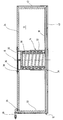
- the compensation device according to the invention is explained in more detail below with reference to the single figure, the figure showing a longitudinal section through the compensation device in its installed position.
- the compensating device has a compensating tank 10, which is provided in its lower edge region with a connection piece 12 which is used to connect to a fluid-carrying line (not shown) which connects the inside of the compensating tank 10 with the inside of the transformer housing (not shown) ) connects.
- a compensation plate 18 Arranged in the expansion tank 10 is a compensation plate 18 which can be moved along an adjustment axis 16 by means of a guide device designated as a whole, which under the action of an energy accumulator in the form of a compression coil spring 20 is in contact with the transformer oil received in the expansion tank (not shown).
- the compensation plate 18 is connected to one end of a bellows 22, which is preferably formed from a stainless steel sheet.
- the other upper end of the bellows 22 is connected to fixed parts of the expansion tank in the form of an upper cover 24.
- the compensating plate 18 limits the volume of air with the bellows 22 within the compensating container 10.
- an opening 26 is provided on the upper end cover 24 and an inlet and outlet line 28 connected to it opens at one end into the interior of the expansion tank 10.
- the other end of this inlet and outlet line 28 can be connected to one Filter unit (not shown) may be connected in order to rule out that any air contaminated with transformer oil can escape unfiltered from the expansion tank, for example if the bellows 22 should fail.
- the guide device designated as a whole with 14 has two mutually displaceable cylindrical sleeves 30, 32, of which the lower one is connected to the compensating plate 18 and the other to the end cover 24, whereby the sleeve 30 guided within the lower sleeve 32 cooperates with a stop surface 34 on the compensating plate 18.
- the outer sleeve 32 can also be continued axially upward in such a way that when the compression spring 20 is pressed together with correspondingly flowing transformer oil into the expansion tank 10 on the lower stop surface, it abuts the underside of the end cover 24 to protect the bellows 22 .
- the two sleeves 30, 32 are also arranged such that they can be displaced relative to one another with a predetermined play.
- the upper sleeve 30, which engages in a passage 36 of the compensating plate 24, is sealed off from the latter by means of a sealing plate 38.
- the compensating device also has a lower housing cover 40, both of which are enclosed on the edge side by a housing jacket 42, this housing jacket 42 enclosing the bellows 22 on the edge side at a predeterminable distance, so that between the compensation plate 18 and the further end cover 40 the fluid-carrying connection in the form of a line (not shown) opens into the expansion tank 10 via the connector 12.
- the transformer oil 10 is thus separated from the air side of the expansion tank 10 via the expansion plate 18 and the bellows 22, and passage of the transformer oil, usually in the form of silicone oil, onto the air side of the expansion tank 10 is excluded.
- the compression spring 20 is compressed by a predetermined amount corresponding to the volume supplied and the compensation plate 18 moves in the figure along its adjustment axis 16 upwards, the bellows 22 around the same distance is compressed.
- the volume of air received in the expansion tank 10 within the bellows 22 is reduced by the amount of the transformer oil that has flowed in and flows out via the opening 26 and the inlet and outlet line 28.
- a maximum provided adjustment distance is provided, which is ended when the underside of the sleeve 30 guided on the inside abuts the stop surface 34 of the compensating plate 18.
- the compensating device can also be arranged below the transformer in the underfloor region of a rail vehicle and the fluid supply can be called up from there.
Landscapes
- Engineering & Computer Science (AREA)
- Power Engineering (AREA)
- Transportation (AREA)
- Mechanical Engineering (AREA)
- Housings And Mounting Of Transformers (AREA)
- Massaging Devices (AREA)
- Optical Communication System (AREA)
- Transformer Cooling (AREA)
- Control Of Motors That Do Not Use Commutators (AREA)
- Vehicle Body Suspensions (AREA)
- Supply Devices, Intensifiers, Converters, And Telemotors (AREA)
- Noodles (AREA)
- Paper (AREA)
Applications Claiming Priority (2)
| Application Number | Priority Date | Filing Date | Title |
|---|---|---|---|
| DE19517401 | 1995-05-15 | ||
| DE19517401A DE19517401C1 (de) | 1995-05-15 | 1995-05-15 | Ausgleichsvorrichtung |
Publications (3)
| Publication Number | Publication Date |
|---|---|
| EP0743661A2 true EP0743661A2 (fr) | 1996-11-20 |
| EP0743661A3 EP0743661A3 (fr) | 1996-12-27 |
| EP0743661B1 EP0743661B1 (fr) | 1999-06-02 |
Family
ID=7761716
Family Applications (1)
| Application Number | Title | Priority Date | Filing Date |
|---|---|---|---|
| EP96105262A Expired - Lifetime EP0743661B1 (fr) | 1995-05-15 | 1996-04-02 | Dispositif compensateur |
Country Status (9)
| Country | Link |
|---|---|
| US (1) | US5709289A (fr) |
| EP (1) | EP0743661B1 (fr) |
| JP (1) | JPH08321422A (fr) |
| AT (1) | ATE180921T1 (fr) |
| DE (2) | DE19517401C1 (fr) |
| DK (1) | DK0743661T3 (fr) |
| ES (1) | ES2135128T3 (fr) |
| GR (1) | GR3030409T3 (fr) |
| NO (1) | NO961957L (fr) |
Cited By (2)
| Publication number | Priority date | Publication date | Assignee | Title |
|---|---|---|---|---|
| WO2000022633A1 (fr) | 1998-10-14 | 2000-04-20 | Hydac Technology Gmbh | Dispositif de compensation pouvant etre utilise dans des transformateurs de vehicules sur rails |
| US10150474B2 (en) * | 2017-01-04 | 2018-12-11 | Robert Bosch Gmbh | Reducing lateral position deviation during an automated lane change |
Families Citing this family (5)
| Publication number | Priority date | Publication date | Assignee | Title |
|---|---|---|---|---|
| US6317286B1 (en) | 1999-01-29 | 2001-11-13 | Seagate Technology Llc | Diaphragm-sealed disc drive |
| US6271470B1 (en) | 2000-01-12 | 2001-08-07 | Abb Power T&D Company Inc. | Oil filled power bushing with piston |
| US6624736B1 (en) | 2000-05-19 | 2003-09-23 | Abb Inc. | Fuse housing with rate release control plug |
| CN104183364B (zh) | 2014-06-23 | 2016-10-05 | 上海联影医疗科技有限公司 | 高压发生器变压油箱 |
| CN114623386B (zh) * | 2022-03-10 | 2023-12-22 | 东营晨辉机械制造有限公司 | 一种油田采油用具有压力保护功能的双通道套压座 |
Family Cites Families (11)
| Publication number | Priority date | Publication date | Assignee | Title |
|---|---|---|---|---|
| DD62619A (fr) * | ||||
| DD62621A (fr) * | ||||
| DE62621C (de) * | H. WEVELSHÜTTEN in Brünen b. Wesel | Bremse an Uhrwerken zum Betriebe von Butterfässern | ||
| DE62619C (de) * | F. H. WHEELAN in Santa Barbara, Grfsch. Santa Barbara, Staat California, V. St. A | Vorrichtung zum Trennen von Materialien nach ihrer verschiedenen Oberfllächenbeschaffenheit | ||
| US2703108A (en) * | 1950-12-04 | 1955-03-01 | Tommy J Mccuistion | Accumulator |
| US3670276A (en) * | 1971-02-11 | 1972-06-13 | Ltv Ling Altec Inc | Hermetic transformer |
| US4225111A (en) * | 1976-11-03 | 1980-09-30 | Corcordia Fluidtechnik Gmbh | Solenoid valve |
| JPS56162815A (en) * | 1980-05-20 | 1981-12-15 | Tamura Seisakusho Co Ltd | Bellows device |
| NO152382C (no) * | 1983-06-06 | 1985-09-18 | Myrens Verksted As | Fluidumakkumulator |
| JPS607108A (ja) * | 1983-06-24 | 1985-01-14 | Mitsubishi Electric Corp | 油入電気機器 |
| DE3800945C1 (fr) * | 1988-01-15 | 1989-02-16 | Daimler-Benz Ag, 7000 Stuttgart, De |
-
1995
- 1995-05-15 DE DE19517401A patent/DE19517401C1/de not_active Expired - Fee Related
-
1996
- 1996-04-02 ES ES96105262T patent/ES2135128T3/es not_active Expired - Lifetime
- 1996-04-02 AT AT96105262T patent/ATE180921T1/de not_active IP Right Cessation
- 1996-04-02 DK DK96105262T patent/DK0743661T3/da active
- 1996-04-02 DE DE59602056T patent/DE59602056D1/de not_active Expired - Fee Related
- 1996-04-02 EP EP96105262A patent/EP0743661B1/fr not_active Expired - Lifetime
- 1996-04-26 US US08/638,236 patent/US5709289A/en not_active Expired - Lifetime
- 1996-05-14 NO NO961957A patent/NO961957L/no unknown
- 1996-05-14 JP JP8119145A patent/JPH08321422A/ja not_active Ceased
-
1999
- 1999-06-03 GR GR990401447T patent/GR3030409T3/el unknown
Cited By (4)
| Publication number | Priority date | Publication date | Assignee | Title |
|---|---|---|---|---|
| WO2000022633A1 (fr) | 1998-10-14 | 2000-04-20 | Hydac Technology Gmbh | Dispositif de compensation pouvant etre utilise dans des transformateurs de vehicules sur rails |
| DE19847313A1 (de) * | 1998-10-14 | 2000-05-04 | Hydac Technology Gmbh | Ausgleichsvorrichtung, geeignet für den Einsatz bei Transformatoren von Schienenfahrzeugen |
| US6549110B1 (en) | 1998-10-14 | 2003-04-15 | Hydac Technology Gmbh | Compensating device suitable for use in railway car transformers |
| US10150474B2 (en) * | 2017-01-04 | 2018-12-11 | Robert Bosch Gmbh | Reducing lateral position deviation during an automated lane change |
Also Published As
| Publication number | Publication date |
|---|---|
| EP0743661A3 (fr) | 1996-12-27 |
| JPH08321422A (ja) | 1996-12-03 |
| NO961957L (no) | 1996-11-18 |
| ATE180921T1 (de) | 1999-06-15 |
| DE19517401C1 (de) | 1996-09-26 |
| ES2135128T3 (es) | 1999-10-16 |
| DE59602056D1 (de) | 1999-07-08 |
| EP0743661B1 (fr) | 1999-06-02 |
| NO961957D0 (no) | 1996-05-14 |
| US5709289A (en) | 1998-01-20 |
| GR3030409T3 (en) | 1999-09-30 |
| DK0743661T3 (da) | 1999-12-13 |
Similar Documents
| Publication | Publication Date | Title |
|---|---|---|
| EP0874676B1 (fr) | Dispositif de filtration a vanne de derivation | |
| DE4330840C1 (de) | Filter für die Reinigung von Flüssigkeiten | |
| DE102010015837B3 (de) | Filteranordnung zum Filtern von Flüssigkeiten | |
| EP0743661B1 (fr) | Dispositif compensateur | |
| DE2533164C3 (de) | Hydraulische Steuereinrichtung für ein Hydrauliksystem | |
| DE2332292A1 (de) | Filteranlage fuer ein hydraulisches system | |
| EP3283192A1 (fr) | Dispositif filtrant et élément filtrant | |
| DE1557773C3 (de) | Regeleinrichtung für die hydraulisch betätigte Hebevorrichtung eines Ackerschleppers. Ausscheidung aus: 1482477 | |
| WO2018054739A1 (fr) | Système d'essieu | |
| EP2729229B1 (fr) | Élément filtrant pour un dispositif de filtration | |
| EP1629208A1 (fr) | Soupape de regulation de pression proportionnelle | |
| EP2496426B1 (fr) | Ressort pneumatique comprenant une soupape de commande pour maintenir une pression résiduelle | |
| DE2718190A1 (de) | Hydraulische kolben-zylinder-anordnung zum kippen des fahrerhauses eines lastkraftwagens | |
| DE9215351U1 (de) | Filtervorrichtung mit Absteuerventil | |
| DE102015221508A1 (de) | Druckausgleichseinrichtung | |
| DE102017001540B4 (de) | Filtervorrichtung, Filtervorrichtungsgehäuse und deren Verwendung | |
| DE4035840C1 (en) | Circuit for differential pressure control between two chambers - ifcluding safety valve which is opened in any limiting values are exceeded | |
| DE102022204446A1 (de) | Filtervorrichtung | |
| DE2742331C2 (de) | Volumenausgleichsbehälter für ein geschlossenes Fluid-Umwälzsystem | |
| EP4169598A1 (fr) | Dispositif comprenant un dispositif de filtrage et un dispositif d'amortissement | |
| EP4543561A1 (fr) | Élément filtrant | |
| DE4135757A1 (de) | Berstsicherung fuer hydraulische anlagen | |
| WO2000022633A1 (fr) | Dispositif de compensation pouvant etre utilise dans des transformateurs de vehicules sur rails | |
| DE1925618C (de) | Filteranordnung | |
| DE10041884B4 (de) | Filtervorrichtung |
Legal Events
| Date | Code | Title | Description |
|---|---|---|---|
| PUAI | Public reference made under article 153(3) epc to a published international application that has entered the european phase |
Free format text: ORIGINAL CODE: 0009012 |
|
| PUAL | Search report despatched |
Free format text: ORIGINAL CODE: 0009013 |
|
| AK | Designated contracting states |
Kind code of ref document: A2 Designated state(s): AT BE CH DE DK ES FI FR GB GR IE IT LI LU NL PT SE |
|
| AK | Designated contracting states |
Kind code of ref document: A3 Designated state(s): AT BE CH DE DK ES FI FR GB GR IE IT LI LU NL PT SE |
|
| 17P | Request for examination filed |
Effective date: 19970127 |
|
| 17Q | First examination report despatched |
Effective date: 19970313 |
|
| GRAG | Despatch of communication of intention to grant |
Free format text: ORIGINAL CODE: EPIDOS AGRA |
|
| GRAG | Despatch of communication of intention to grant |
Free format text: ORIGINAL CODE: EPIDOS AGRA |
|
| GRAH | Despatch of communication of intention to grant a patent |
Free format text: ORIGINAL CODE: EPIDOS IGRA |
|
| GRAH | Despatch of communication of intention to grant a patent |
Free format text: ORIGINAL CODE: EPIDOS IGRA |
|
| GRAA | (expected) grant |
Free format text: ORIGINAL CODE: 0009210 |
|
| AK | Designated contracting states |
Kind code of ref document: B1 Designated state(s): AT BE CH DE DK ES FI FR GB GR IE IT LI LU NL PT SE |
|
| REF | Corresponds to: |
Ref document number: 180921 Country of ref document: AT Date of ref document: 19990615 Kind code of ref document: T |
|
| ET | Fr: translation filed | ||
| REG | Reference to a national code |
Ref country code: CH Ref legal event code: NV Representative=s name: ISLER & PEDRAZZINI AG Ref country code: CH Ref legal event code: EP |
|
| REF | Corresponds to: |
Ref document number: 59602056 Country of ref document: DE Date of ref document: 19990708 |
|
| REG | Reference to a national code |
Ref country code: IE Ref legal event code: FG4D Free format text: GERMAN |
|
| GBT | Gb: translation of ep patent filed (gb section 77(6)(a)/1977) |
Effective date: 19990708 |
|
| REG | Reference to a national code |
Ref country code: ES Ref legal event code: FG2A Ref document number: 2135128 Country of ref document: ES Kind code of ref document: T3 |
|
| REG | Reference to a national code |
Ref country code: PT Ref legal event code: SC4A Free format text: AVAILABILITY OF NATIONAL TRANSLATION Effective date: 19990901 |
|
| REG | Reference to a national code |
Ref country code: DK Ref legal event code: T3 |
|
| PGFP | Annual fee paid to national office [announced via postgrant information from national office to epo] |
Ref country code: IE Payment date: 20000321 Year of fee payment: 5 |
|
| PG25 | Lapsed in a contracting state [announced via postgrant information from national office to epo] |
Ref country code: DK Free format text: LAPSE BECAUSE OF NON-PAYMENT OF DUE FEES Effective date: 20000402 |
|
| PG25 | Lapsed in a contracting state [announced via postgrant information from national office to epo] |
Ref country code: ES Free format text: LAPSE BECAUSE OF NON-PAYMENT OF DUE FEES Effective date: 20000403 |
|
| PGFP | Annual fee paid to national office [announced via postgrant information from national office to epo] |
Ref country code: LU Payment date: 20000403 Year of fee payment: 5 |
|
| PGFP | Annual fee paid to national office [announced via postgrant information from national office to epo] |
Ref country code: FI Payment date: 20000404 Year of fee payment: 5 |
|
| PLBE | No opposition filed within time limit |
Free format text: ORIGINAL CODE: 0009261 |
|
| STAA | Information on the status of an ep patent application or granted ep patent |
Free format text: STATUS: NO OPPOSITION FILED WITHIN TIME LIMIT |
|
| PGFP | Annual fee paid to national office [announced via postgrant information from national office to epo] |
Ref country code: BE Payment date: 20000413 Year of fee payment: 5 |
|
| PGFP | Annual fee paid to national office [announced via postgrant information from national office to epo] |
Ref country code: NL Payment date: 20000428 Year of fee payment: 5 |
|
| PG25 | Lapsed in a contracting state [announced via postgrant information from national office to epo] |
Ref country code: GR Free format text: LAPSE BECAUSE OF NON-PAYMENT OF DUE FEES Effective date: 20000430 |
|
| 26N | No opposition filed | ||
| PG25 | Lapsed in a contracting state [announced via postgrant information from national office to epo] |
Ref country code: PT Free format text: LAPSE BECAUSE OF NON-PAYMENT OF DUE FEES Effective date: 20001031 |
|
| REG | Reference to a national code |
Ref country code: DK Ref legal event code: EBP |
|
| REG | Reference to a national code |
Ref country code: PT Ref legal event code: MM4A Free format text: LAPSE DUE TO NON-PAYMENT OF FEES Effective date: 20001031 |
|
| PGFP | Annual fee paid to national office [announced via postgrant information from national office to epo] |
Ref country code: GB Payment date: 20010302 Year of fee payment: 6 |
|
| PGFP | Annual fee paid to national office [announced via postgrant information from national office to epo] |
Ref country code: FR Payment date: 20010329 Year of fee payment: 6 |
|
| PG25 | Lapsed in a contracting state [announced via postgrant information from national office to epo] |
Ref country code: LU Free format text: LAPSE BECAUSE OF NON-PAYMENT OF DUE FEES Effective date: 20010402 Ref country code: IE Free format text: LAPSE BECAUSE OF NON-PAYMENT OF DUE FEES Effective date: 20010402 Ref country code: FI Free format text: LAPSE BECAUSE OF NON-PAYMENT OF DUE FEES Effective date: 20010402 |
|
| PGFP | Annual fee paid to national office [announced via postgrant information from national office to epo] |
Ref country code: CH Payment date: 20010427 Year of fee payment: 6 Ref country code: AT Payment date: 20010427 Year of fee payment: 6 |
|
| PG25 | Lapsed in a contracting state [announced via postgrant information from national office to epo] |
Ref country code: BE Free format text: LAPSE BECAUSE OF NON-PAYMENT OF DUE FEES Effective date: 20010430 |
|
| BERE | Be: lapsed |
Owner name: HYDAC TECHNOLOGY G.M.B.H. Effective date: 20010430 |
|
| PG25 | Lapsed in a contracting state [announced via postgrant information from national office to epo] |
Ref country code: NL Free format text: LAPSE BECAUSE OF NON-PAYMENT OF DUE FEES Effective date: 20011101 |
|
| REG | Reference to a national code |
Ref country code: GB Ref legal event code: IF02 |
|
| NLV4 | Nl: lapsed or anulled due to non-payment of the annual fee |
Effective date: 20011101 |
|
| REG | Reference to a national code |
Ref country code: IE Ref legal event code: MM4A |
|
| PG25 | Lapsed in a contracting state [announced via postgrant information from national office to epo] |
Ref country code: GB Free format text: LAPSE BECAUSE OF NON-PAYMENT OF DUE FEES Effective date: 20020402 Ref country code: AT Free format text: LAPSE BECAUSE OF NON-PAYMENT OF DUE FEES Effective date: 20020402 |
|
| PG25 | Lapsed in a contracting state [announced via postgrant information from national office to epo] |
Ref country code: LI Free format text: LAPSE BECAUSE OF NON-PAYMENT OF DUE FEES Effective date: 20020430 Ref country code: CH Free format text: LAPSE BECAUSE OF NON-PAYMENT OF DUE FEES Effective date: 20020430 |
|
| GBPC | Gb: european patent ceased through non-payment of renewal fee |
Effective date: 20020402 |
|
| REG | Reference to a national code |
Ref country code: CH Ref legal event code: PL |
|
| PG25 | Lapsed in a contracting state [announced via postgrant information from national office to epo] |
Ref country code: FR Free format text: LAPSE BECAUSE OF NON-PAYMENT OF DUE FEES Effective date: 20021231 |
|
| REG | Reference to a national code |
Ref country code: FR Ref legal event code: ST |
|
| PGFP | Annual fee paid to national office [announced via postgrant information from national office to epo] |
Ref country code: SE Payment date: 20030318 Year of fee payment: 8 |
|
| PG25 | Lapsed in a contracting state [announced via postgrant information from national office to epo] |
Ref country code: SE Free format text: LAPSE BECAUSE OF NON-PAYMENT OF DUE FEES Effective date: 20040403 |
|
| REG | Reference to a national code |
Ref country code: ES Ref legal event code: FD2A Effective date: 20010514 |
|
| EUG | Se: european patent has lapsed | ||
| PG25 | Lapsed in a contracting state [announced via postgrant information from national office to epo] |
Ref country code: IT Free format text: LAPSE BECAUSE OF NON-PAYMENT OF DUE FEES;WARNING: LAPSES OF ITALIAN PATENTS WITH EFFECTIVE DATE BEFORE 2007 MAY HAVE OCCURRED AT ANY TIME BEFORE 2007. THE CORRECT EFFECTIVE DATE MAY BE DIFFERENT FROM THE ONE RECORDED. Effective date: 20050402 |
|
| PGFP | Annual fee paid to national office [announced via postgrant information from national office to epo] |
Ref country code: DE Payment date: 20080508 Year of fee payment: 13 |
|
| PG25 | Lapsed in a contracting state [announced via postgrant information from national office to epo] |
Ref country code: DE Free format text: LAPSE BECAUSE OF NON-PAYMENT OF DUE FEES Effective date: 20091103 |