EP0743673A2 - Filament bispiralé pour lampe à incandescence - Google Patents
Filament bispiralé pour lampe à incandescence Download PDFInfo
- Publication number
- EP0743673A2 EP0743673A2 EP96303522A EP96303522A EP0743673A2 EP 0743673 A2 EP0743673 A2 EP 0743673A2 EP 96303522 A EP96303522 A EP 96303522A EP 96303522 A EP96303522 A EP 96303522A EP 0743673 A2 EP0743673 A2 EP 0743673A2
- Authority
- EP
- European Patent Office
- Prior art keywords
- leg portions
- coil
- filament
- lamp
- coiled
- Prior art date
- Legal status (The legal status is an assumption and is not a legal conclusion. Google has not performed a legal analysis and makes no representation as to the accuracy of the status listed.)
- Granted
Links
- 238000004519 manufacturing process Methods 0.000 claims abstract description 33
- 238000004804 winding Methods 0.000 claims abstract description 25
- ZOKXTWBITQBERF-UHFFFAOYSA-N Molybdenum Chemical compound [Mo] ZOKXTWBITQBERF-UHFFFAOYSA-N 0.000 claims description 11
- 229910052750 molybdenum Inorganic materials 0.000 claims description 11
- 239000011733 molybdenum Substances 0.000 claims description 11
- 239000011888 foil Substances 0.000 claims description 9
- 229910052721 tungsten Inorganic materials 0.000 claims description 5
- 239000010937 tungsten Substances 0.000 claims description 5
- 238000000137 annealing Methods 0.000 claims 1
- WFKWXMTUELFFGS-UHFFFAOYSA-N tungsten Chemical compound [W] WFKWXMTUELFFGS-UHFFFAOYSA-N 0.000 claims 1
- 238000007598 dipping method Methods 0.000 abstract description 5
- 230000015572 biosynthetic process Effects 0.000 abstract description 2
- 238000000034 method Methods 0.000 description 12
- 238000005245 sintering Methods 0.000 description 12
- 125000006850 spacer group Chemical group 0.000 description 7
- 238000007789 sealing Methods 0.000 description 6
- 230000008901 benefit Effects 0.000 description 5
- 229910052736 halogen Inorganic materials 0.000 description 5
- -1 tungsten halogen Chemical class 0.000 description 4
- UFHFLCQGNIYNRP-UHFFFAOYSA-N Hydrogen Chemical compound [H][H] UFHFLCQGNIYNRP-UHFFFAOYSA-N 0.000 description 2
- 229910052739 hydrogen Inorganic materials 0.000 description 2
- 239000001257 hydrogen Substances 0.000 description 2
- WABPQHHGFIMREM-UHFFFAOYSA-N lead(0) Chemical compound [Pb] WABPQHHGFIMREM-UHFFFAOYSA-N 0.000 description 2
- 238000009966 trimming Methods 0.000 description 2
- 108091081062 Repeated sequence (DNA) Proteins 0.000 description 1
- 230000002411 adverse Effects 0.000 description 1
- 238000010276 construction Methods 0.000 description 1
- 230000000694 effects Effects 0.000 description 1
- 230000008030 elimination Effects 0.000 description 1
- 238000003379 elimination reaction Methods 0.000 description 1
- 239000007789 gas Substances 0.000 description 1
- 238000003780 insertion Methods 0.000 description 1
- 230000037431 insertion Effects 0.000 description 1
- 238000009434 installation Methods 0.000 description 1
- 239000000463 material Substances 0.000 description 1
- 230000000717 retained effect Effects 0.000 description 1
- 238000000926 separation method Methods 0.000 description 1
Images

Classifications
-
- H—ELECTRICITY
- H01—ELECTRIC ELEMENTS
- H01K—ELECTRIC INCANDESCENT LAMPS
- H01K3/00—Apparatus or processes adapted to the manufacture, installing, removal, or maintenance of incandescent lamps or parts thereof
- H01K3/02—Manufacture of incandescent bodies
-
- H—ELECTRICITY
- H01—ELECTRIC ELEMENTS
- H01K—ELECTRIC INCANDESCENT LAMPS
- H01K1/00—Details
- H01K1/02—Incandescent bodies
- H01K1/14—Incandescent bodies characterised by the shape
-
- H—ELECTRICITY
- H01—ELECTRIC ELEMENTS
- H01K—ELECTRIC INCANDESCENT LAMPS
- H01K1/00—Details
- H01K1/02—Incandescent bodies
- H01K1/16—Electric connection thereto
Definitions
- This invention relates to an improved small coiled-coil filament configuration for use with an incandescent lamp such as for instance, a tungsten halogen incandescent lamp. More particularly, this invention relates to such a coiled-coil filament configuration as can be readily produced on an automated high speed manufacturing system at a significant cost savings over existing manufacturing techniques.
- Small coiled-coil filament configurations are typically utilized in some tungsten halogen incandescent lamps because of their high voltage capabilities and luminous efficacy as compared to a conventional larger coiled-coil filament configuration.
- Examples of tungsten halogen lamps utilizing small coiled-coil filaments can be found in high voltage photographic axial projection lamps.
- One such coiled-coil filament configuration is typically the transverse filament designated CC-6.
- Such small CC-6 filament has a length of about 5 mm.
- Other coiled-coil lengths are also utilized for various lighting applications and would benefit equally as well from the present invention.
- the cost of manufacturing the filament is expensive and very labor intensive.
- the resulting filament product must include spaces between the body of the coiled-coil arrangement and the leg portions that are welded to the molybdenum foils used for the pressed seal of the lamp envelope.
- spud elements are sometimes needed within the leg portions of the coiled-coil arrangement disposed in the seal.
- primary coiling is done on a piece of equipment which winds the primary coil on a primary molybdenum mandrel wherein spacing is formed between the leg segments and the secondary coil body by use of a segmented cam.
- the spaces formed by the segmented cam are needed for subsequent manufacturing operations involving Picco or wax dipping of the end segments so that during the step of dissolving the primary mandrel from the main coil body, primary mandrel spuds are retained in the leg segments.
- secondary coiling is done on a secondary mandrel and such secondary coiling is done so as to achieve approximately a 75 degrees or 0.2 turn overwind of the leg portions.
- prewound sintering forms are manually screwed into the secondary coil to hold the correct coil pitch during a subsequent sintering operation. Additionally, the coil legs are bent by hand to align the legs and are then manually trimmed to the required length. Once the coils have been sintered to stress relieve and to set the shape of the coils, the sintering forms are removed and the legs are then Picco or wax-dipped to allow for retaining the molybdenum mandrel in the legs thus becoming the spuds. Once the primary mandrel has been dissolved from the coil body and a portion of the legs, the Picco or wax residue must be removed. Then the coiled-coil filament is ready for mounting and sealing into the lamp envelope and final lamp assembly.
- a coiled-coil configuration could be developed that could be manufactured on an automated high speed manufacturing system thus eliminating the need for costly, less uniform manual operations that are presently used. It would be further advantageous if such a coiled-coil filament could achieve improved structural advantages over the existing coiled-coil configuration particularly by elimination of the spacer portion while at the same time maintaining the high voltage and efficacy characteristics of existing small coiled-coil filaments.
- the present invention provides an improved coiled-coil filament arrangement for use in a high efficiency incandescent lamp such as a tungsten halogen lamp.
- This improved coiled-coil arrangement provides for a more uniform and sturdy construction as compared to similar conventional coiled-coils and does so in a manner that can be implemented on high speed automated manufacturing equipment thereby reducing manufacturing costs and eliminating the need for manual labor to perform various subassembly operations.
- a coiled-coil filament arrangement for use with an incandescent lamp wherein the coiled-coil filament is disposed within a lamp envelope portion of the incandescent lamp in a manner such that lead wires and foils connected to the filament member extend through a sealed region of the lamp envelope to allow connection of power thereto.
- the coiled-coil filament member includes a primary coil winding which is wound on a primary mandrel so as to achieve a substantially uniform distance between successive turns of the primary coil winding.
- the coiled-coil filament member also includes a secondary coil winding formed by winding the primary coil winding on a second mandrel, this secondary coil winding forming a main coil body. End portions of the primary coil winding form legs of the coiled-coil filament, such legs extending away from the main coil body into the seal region of the lamp envelope substantially parallel to one another.
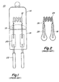
- an incandescent lamp 10 which utilizes a coiled-coil filament configuration 12 constructed according to known techniques, includes a lamp envelope 14 having a sealed region 16 formed at one end. Leg portions 18 associated with the coiled-coil filament member 12 are welded to a pair of molybdenum foil members 20. The molybdenum foil members 20 also have welded to the opposite end thereof, respective lead wire members 22 which extend out of the sealed region 16 so as to allow for connection of power thereto. As seen in Fig. 1, a portion of the leg portions 18, the molybdenum foil members 20 and a portion of the respective lead wire members 22 are all sealed within the sealed region 16 of the lamp envelope 14.
- sealing lamp envelope 14 can include either a press or pinch seal process, as well as a heat shrinking process such sealing processes being known in the art.
- shape of the lamp envelope 14 is illustrated as a single ended lamp product, such as can typically be utilized in a projection lamp product that includes a reflector portion such as photo-axial lamps offered by GE Lighting. It should be appreciated that the present invention can be incorporated into various types of lamp envelope configurations as well as those utilizing various sealing types and as such, is not intended to be limited to the illustrations presented herein.
- the coiled-coil filament member 12 disposed within the lamp envelope 14 of Fig. 1 includes a main coil body portion 24 from which the leg portions 18 extend. Separating the main coil body 24 from the leg portions 18 are respective spaces 26 the purpose for which will be discussed hereinafter in further detail. Disposed within the leg portions 18 below the spaces 26 are spuds 28 which are formed by portions of the primary mandrel element 30 described below in relation to the manufacturing process utilized for the production of the coiled-coil filament 12 of the prior art.
- the process for manufacturing the coiled-coil filament 12 begins with the step of winding the primary coil 12a around a primary mandrel 30 made of molybdenum.
- the equipment used to perform the coiling operation includes a segmented cam (not shown) that is effective for forming repeated sequences of spacers 26, leg portions 18, and main coil bodies 24.
- the primary coil 12a will typically be annealed in hydrogen so as to stress relieve, soften, and permanently fix the primary coiling.
- the primary coil is then wound on a secondary mandrel 32 to form the secondary or main coil body 24.
- the existing equipment (not shown) for performing the secondary coiling will also overwind the ends of the primary coil segment by approximately 75 degrees or 0.2 turns.
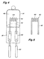
- prewound sintering forms 36 are manually screwed into the overwound coil segment 34 so as to maintain the correct coil pitch during a subsequent sintering operation, such manual operation being illustrated in Fig. 3C.
- the subsequent step to the sintering form insertion of Fig. 3C involves the manual alignment of the coil leg portions 18 while the sintering form 36 is still screwed into the secondary coil of the main coil body 24.
- the alignment of the leg portions by hand results in a separation of the leg portions from each other at the region where such leg portions 18 first extend away from the main coil body 24 while then tapering towards each other at the bottom portion of the leg portions 18.
- the leg portions 18 are manually trimmed to the same length as shown in Fig. 3E.
- the coiled-coil filament members 12 are then sintered in hydrogen to stress relieve and to set the coil shape. During this operation, the legs must be held in the exact position that is finally required. It should be understood that throughout the previously outlined steps, there are a significant number of steps that are done manually which, by the nature of such an operation, will likely result in variation in the actual characteristics of the filament members 12 as well as proving significantly more expensive and time consuming to manufacture. In fact, even after the sintering process, a manual step of removing the sintering form 36 is required.
- the leg portions 18 of the coiled-coil filament member 12 are Picco or wax dipped so that the primary mandrel in the leg portions 18 remains intact and forms the spud members 38 of the finished coiled-coil filament 12 once the primary mandrel is dissolved. Then, to finish the coiled-coil filament manufacture, the Picco or wax dipping must be removed before the filament member 12 can be inserted and sealed into the lamp envelope 14.
- the present invention in contrast to the multitude of manufacturing steps used in producing the prior art coiled-coil filament member 12, many of which are manually performed, the present invention as described with reference to figures 4 through 6D provides a coiled-coil filament 40 which is readily adaptable to a high speed automated manufacturing operation such that all filaments coming off of the production line are substantially similar to one another, and wherein such production is accomplished at a cost and time savings as compared to existing techniques.
- the coiled-coil filament member 40 of the present invention is provided with a new and improved leg portion configuration that avoids the need for a spud member and yet provides the necessary support strength both during lamp assembly as well as during continued lamp operation.
- the spud may not be needed for support, a spud may be provided to maintain seal integrity throughout the life of the lamp.
- the present coiled-coil filament member 40 allows for a more precise alignment of the main coil body portion 44 within the lamp envelope 14. It has been found that, in the coiled-coil filament configurations such as found in the prior art, by virtue of the offset alignment at the tops of the leg portions 18, if the pinch seal process is not exact, the step of pinch sealing the lamp envelope can have the effect of tilting the alignment of the main coil body away from the desired central position within the lamp envelope 14.
- coiled-coil filament member 40 of the present invention includes the main coil body 44 which is substantially the same as that of the prior art; that is, the main coil body 44 is comprised of a secondary coil portion wound using a primary coil portion.
- the filament member 40 of the present invention utilizes the primary coil portion in a continuous manner, from the leg portions 42 through the main coil body 44, and the use of spacers 26 between such leg portions 42 and main coil body 44 is avoided.
- the present invention provides a coiled-coil filament 40 which does not always require the use of a spud member in the leg portions 42.
- FIG. 5 illustrates the application of the coiled-coil filament member 40 of the present invention into the tungsten-halogen light source 10 as was shown in Fig. 1.
- the coiled-coil filament 40 is disposed at about the central region of the light envelope chamber 46 with the leg portions of the filament member 40 extending downward in a parallel manner to one another into the seal region 16 of the lamp envelope 14.
- the parallel relationship of the leg portions 42 is achieved by a helical bend 48 which is made where the leg portions extend off from the main coil body 44. It can be appreciated that by the use of the spacer 26 of the prior art coiled-coil filament 12, such a bend which allows for the parallel relationship of the leg portions could not readily be achieved without adversely affecting the spaced primary coiling at the spacer region 26.
- leg portions 42 of the coiled-coil filament 40 are welded to molybdenum foil members 20 on one end.
- lead wires 22 which extend out from the lamp envelope 14 to provide for connection of power to the light source 10.
- the present invention can be achieved by means of a manufacturing operation that yields benefits in terms of cost, manufacturing time and uniformity of results for all production runs.
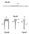
- the manufacturing operation can be seen in Fig. 6A as requiring a continuous run of primary coiling 52 over a length of wire, such primary coiling being wound on a primary mandrel similar to that used in Fig. 3A but without the need for a cam member to provide spacers 26 since such spacers have been eliminated.
- Figures 6B and 6C show respectively a front view and a side view of the primary coil wound on a secondary mandrel so as to achieve the main coil body 44. From the side view perspective of Fig. 6C, it can be seen that the leg portions are parallel to one another and that their respective lengths are substantially the same. The attainment of the parallel leg portion 18 configuration can be achieved by means of overwinding the secondary coiling operation a predetermined amount that accounts for the fact that the coil leg portions will spring back such predetermined amount into the parallel alignment as shown in Fig. 6C.
- the coiled-coil filament 40 is lighted, that is, a voltage is applied with the coiled-coil filament in forming gas typically comprised of H 2 and N 2 .
- the applied voltage is that voltage just below what would ordinarily melt the primary mandrel, and is applied to set the shape of the coiled-coil filament member 40. In this manner, the coiled-coil filament of the present invention is locked in the desired shape without the need for the manual installation of a sintering form and without the need to perform an actual sintering operation.
- each coil can be set in shape immediately after coiling rather than having to perform a batch furnace operation to anneal and set the coil shape of a batch of filaments as is done using the process of the prior art.
- the primary mandrel may then be dissolved in its entirety without leaving spud members within the leg portions 42 of the filament 40.
- the step of Picco or wax dipping of the leg portions so as to allow for the formation of the spud members of the prior art coiled-coil filament 12 has been avoided.
- the subsequent step of removing the Picco or wax-dipping material prior to sealing the filament member 12 into the lamp envelope is also avoided.
- the coiled-coil filament 40 can be mounted and sealed into the lamp envelope 14 and sealed using either a pinch or press seal technique or a heat shrink technique, all of which are well known in the lighting field.
Landscapes
- Engineering & Computer Science (AREA)
- Manufacturing & Machinery (AREA)
- Resistance Heating (AREA)
- Wire Processing (AREA)
Applications Claiming Priority (2)
| Application Number | Priority Date | Filing Date | Title |
|---|---|---|---|
| US444952 | 1995-05-19 | ||
| US08/444,952 US5680003A (en) | 1995-05-19 | 1995-05-19 | Coiled-coil filament design for an incandescent lamp |
Publications (3)
| Publication Number | Publication Date |
|---|---|
| EP0743673A2 true EP0743673A2 (fr) | 1996-11-20 |
| EP0743673A3 EP0743673A3 (fr) | 1997-11-05 |
| EP0743673B1 EP0743673B1 (fr) | 2002-01-09 |
Family
ID=23767045
Family Applications (1)
| Application Number | Title | Priority Date | Filing Date |
|---|---|---|---|
| EP96303522A Expired - Lifetime EP0743673B1 (fr) | 1995-05-19 | 1996-05-17 | Filament bispiralé pour lampe à incandescence |
Country Status (3)
| Country | Link |
|---|---|
| US (1) | US5680003A (fr) |
| EP (1) | EP0743673B1 (fr) |
| DE (1) | DE69618376T2 (fr) |
Cited By (2)
| Publication number | Priority date | Publication date | Assignee | Title |
|---|---|---|---|---|
| CN1118861C (zh) * | 1996-12-20 | 2003-08-20 | 电灯专利信托有限公司 | 螺旋形卷绕的灯丝的制造方法和按此法制造的灯丝及灯 |
| WO2006066533A1 (fr) * | 2004-12-22 | 2006-06-29 | Patent-Treuhand- Gesellschaft Für Elektrische Glühlampen Mbh | Procede de fixation et lampe et ainsi produite |
Families Citing this family (5)
| Publication number | Priority date | Publication date | Assignee | Title |
|---|---|---|---|---|
| US5842219A (en) * | 1996-03-14 | 1998-11-24 | International Business Machines Corporation | Method and system for providing a multiple property searching capability within an object-oriented distributed computing network |
| US6204508B1 (en) | 1998-08-07 | 2001-03-20 | Axcelis Technologies, Inc. | Toroidal filament for plasma generation |
| US6639364B1 (en) * | 2000-06-29 | 2003-10-28 | Koninklijke Philips Electronics N.V. | Halogen incandescent capsule having filament leg clamped in press seal |
| KR100505040B1 (ko) | 2003-12-19 | 2005-07-29 | 삼성전자주식회사 | 이온 소스 및 이를 갖는 이온 주입 장치 |
| DE102004044365A1 (de) * | 2004-09-10 | 2006-03-16 | Patent-Treuhand-Gesellschaft für elektrische Glühlampen mbH | Elektrische Glühlampe |
Family Cites Families (10)
| Publication number | Priority date | Publication date | Assignee | Title |
|---|---|---|---|---|
| NL76841C (fr) * | 1940-11-23 | |||
| US2359302A (en) * | 1942-06-11 | 1944-10-03 | Tung Sol Lamp Works Inc | Incandescent lamp and method of manufacture |
| US2759498A (en) * | 1949-05-28 | 1956-08-21 | Sylvania Electric Prod | Apparatus for forming lamp filaments |
| US3048201A (en) * | 1959-12-29 | 1962-08-07 | Westinghouse Electric Corp | Article-forming device |
| US3285293A (en) * | 1966-01-03 | 1966-11-15 | Sylvania Electric Prod | Filament forming |
| US3670377A (en) * | 1970-05-12 | 1972-06-20 | Westinghouse Electric Corp | Method of manufacturing an electric lamp filament having a coiled-coil body portion with oriented off-set legs |
| US3668391A (en) * | 1970-08-19 | 1972-06-06 | Sylvania Electric Prod | Tungsten halogen lamp having improved seal of molybdenum aluminide |
| US3767959A (en) * | 1971-02-24 | 1973-10-23 | Sylvania Electric Prod | Filament mount for a single ended tungsten halogen lamp |
| US4354137A (en) * | 1980-07-15 | 1982-10-12 | Westinghouse Electric Corp. | Incandescent lamp having seal-anchored filament mount, and method of making such lamp |
| US4683397A (en) * | 1986-04-14 | 1987-07-28 | Gte Products Corporation | Compact incandescent coiled coil filament |
-
1995
- 1995-05-19 US US08/444,952 patent/US5680003A/en not_active Expired - Fee Related
-
1996
- 1996-05-17 DE DE69618376T patent/DE69618376T2/de not_active Expired - Fee Related
- 1996-05-17 EP EP96303522A patent/EP0743673B1/fr not_active Expired - Lifetime
Cited By (2)
| Publication number | Priority date | Publication date | Assignee | Title |
|---|---|---|---|---|
| CN1118861C (zh) * | 1996-12-20 | 2003-08-20 | 电灯专利信托有限公司 | 螺旋形卷绕的灯丝的制造方法和按此法制造的灯丝及灯 |
| WO2006066533A1 (fr) * | 2004-12-22 | 2006-06-29 | Patent-Treuhand- Gesellschaft Für Elektrische Glühlampen Mbh | Procede de fixation et lampe et ainsi produite |
Also Published As
| Publication number | Publication date |
|---|---|
| EP0743673B1 (fr) | 2002-01-09 |
| DE69618376D1 (de) | 2002-02-14 |
| DE69618376T2 (de) | 2002-10-17 |
| EP0743673A3 (fr) | 1997-11-05 |
| US5680003A (en) | 1997-10-21 |
Similar Documents
| Publication | Publication Date | Title |
|---|---|---|
| EP0743673B1 (fr) | Filament bispiralé pour lampe à incandescence | |
| US4812710A (en) | Halogen incandescent lamp with high reliability filament connection, and method of manufacture | |
| US4864184A (en) | Lamp construction and method of manufacture | |
| JP2003031179A (ja) | 小型蛍光灯、並びにそれを製造する方法及び装置 | |
| US5499937A (en) | Cathode for high intensity discharge lamp | |
| US4739220A (en) | Method of making a single-based metal halide high-pressure discharge lamp, and lamp made according to the method | |
| US3725720A (en) | Electric lamp mount having a beaded filament coil | |
| US3840953A (en) | Method of assembling a filament-mount for a single-ended incandescent lamp | |
| EP0149282B1 (fr) | Méthode de fabrication de filaments enroulés hélicoidalement et filaments fabriqués selon cette méthode | |
| US4868451A (en) | Lamp filament support construction | |
| NL8005156A (nl) | Elektrische gloeilamp. | |
| US1013572A (en) | Method of shaping filaments. | |
| US1865490A (en) | Method of producing uniform length filaments | |
| US3670377A (en) | Method of manufacturing an electric lamp filament having a coiled-coil body portion with oriented off-set legs | |
| JPH04303556A (ja) | フィラメントの成形方法 | |
| WO1999060604A1 (fr) | Lampe incandescente a pinces de filament enroule sans mandrin | |
| US3189779A (en) | Frame grid and method of fabrication | |
| US1871018A (en) | Coiled lamp filament | |
| US3245132A (en) | Method of manufacturing a heater | |
| US3629914A (en) | Method of making an elongated singly coiled filament and mounting it in a tubular incandescent lamp | |
| GB2100506A (en) | An incandescent lamp coil | |
| US5680009A (en) | Method of making an electric incandescent lamp, and electric lamp made in accordance with the method | |
| US3253620A (en) | Making grid-like elements for electron tubes | |
| US3351407A (en) | Incandescent lamp | |
| JPH0393130A (ja) | 電子管陰極用ヒータ構体の製造方法 |
Legal Events
| Date | Code | Title | Description |
|---|---|---|---|
| PUAI | Public reference made under article 153(3) epc to a published international application that has entered the european phase |
Free format text: ORIGINAL CODE: 0009012 |
|
| AK | Designated contracting states |
Kind code of ref document: A2 Designated state(s): DE FR GB IT |
|
| PUAL | Search report despatched |
Free format text: ORIGINAL CODE: 0009013 |
|
| AK | Designated contracting states |
Kind code of ref document: A3 Designated state(s): DE FR GB IT |
|
| 17P | Request for examination filed |
Effective date: 19980506 |
|
| 17Q | First examination report despatched |
Effective date: 19990401 |
|
| GRAG | Despatch of communication of intention to grant |
Free format text: ORIGINAL CODE: EPIDOS AGRA |
|
| GRAG | Despatch of communication of intention to grant |
Free format text: ORIGINAL CODE: EPIDOS AGRA |
|
| GRAH | Despatch of communication of intention to grant a patent |
Free format text: ORIGINAL CODE: EPIDOS IGRA |
|
| GRAH | Despatch of communication of intention to grant a patent |
Free format text: ORIGINAL CODE: EPIDOS IGRA |
|
| GRAA | (expected) grant |
Free format text: ORIGINAL CODE: 0009210 |
|
| REG | Reference to a national code |
Ref country code: GB Ref legal event code: IF02 |
|
| AK | Designated contracting states |
Kind code of ref document: B1 Designated state(s): DE FR GB IT |
|
| REF | Corresponds to: |
Ref document number: 69618376 Country of ref document: DE Date of ref document: 20020214 |
|
| ET | Fr: translation filed | ||
| PLBE | No opposition filed within time limit |
Free format text: ORIGINAL CODE: 0009261 |
|
| STAA | Information on the status of an ep patent application or granted ep patent |
Free format text: STATUS: NO OPPOSITION FILED WITHIN TIME LIMIT |
|
| 26N | No opposition filed | ||
| PGFP | Annual fee paid to national office [announced via postgrant information from national office to epo] |
Ref country code: DE Payment date: 20080630 Year of fee payment: 13 |
|
| PGFP | Annual fee paid to national office [announced via postgrant information from national office to epo] |
Ref country code: IT Payment date: 20080528 Year of fee payment: 13 |
|
| PGFP | Annual fee paid to national office [announced via postgrant information from national office to epo] |
Ref country code: GB Payment date: 20080529 Year of fee payment: 13 |
|
| GBPC | Gb: european patent ceased through non-payment of renewal fee |
Effective date: 20090517 |
|
| REG | Reference to a national code |
Ref country code: FR Ref legal event code: ST Effective date: 20100129 |
|
| PG25 | Lapsed in a contracting state [announced via postgrant information from national office to epo] |
Ref country code: FR Free format text: LAPSE BECAUSE OF NON-PAYMENT OF DUE FEES Effective date: 20090602 |
|
| PGFP | Annual fee paid to national office [announced via postgrant information from national office to epo] |
Ref country code: FR Payment date: 20080519 Year of fee payment: 13 |
|
| PG25 | Lapsed in a contracting state [announced via postgrant information from national office to epo] |
Ref country code: GB Free format text: LAPSE BECAUSE OF NON-PAYMENT OF DUE FEES Effective date: 20090517 |
|
| PG25 | Lapsed in a contracting state [announced via postgrant information from national office to epo] |
Ref country code: DE Free format text: LAPSE BECAUSE OF NON-PAYMENT OF DUE FEES Effective date: 20091201 |
|
| PG25 | Lapsed in a contracting state [announced via postgrant information from national office to epo] |
Ref country code: IT Free format text: LAPSE BECAUSE OF NON-PAYMENT OF DUE FEES Effective date: 20090517 |