EP0744375A1 - A lifting jack for a car - Google Patents
A lifting jack for a car Download PDFInfo
- Publication number
- EP0744375A1 EP0744375A1 EP96108252A EP96108252A EP0744375A1 EP 0744375 A1 EP0744375 A1 EP 0744375A1 EP 96108252 A EP96108252 A EP 96108252A EP 96108252 A EP96108252 A EP 96108252A EP 0744375 A1 EP0744375 A1 EP 0744375A1
- Authority
- EP
- European Patent Office
- Prior art keywords
- arms
- support bracket
- jack according
- upper arm
- bearing element
- Prior art date
- Legal status (The legal status is an assumption and is not a legal conclusion. Google has not performed a legal analysis and makes no representation as to the accuracy of the status listed.)
- Withdrawn
Links
- 230000000284 resting effect Effects 0.000 description 4
- 210000002105 tongue Anatomy 0.000 description 4
- 238000004519 manufacturing process Methods 0.000 description 1
- 238000003466 welding Methods 0.000 description 1
Images

Classifications
-
- B—PERFORMING OPERATIONS; TRANSPORTING
- B66—HOISTING; LIFTING; HAULING
- B66F—HOISTING, LIFTING, HAULING OR PUSHING, NOT OTHERWISE PROVIDED FOR, e.g. DEVICES WHICH APPLY A LIFTING OR PUSHING FORCE DIRECTLY TO THE SURFACE OF A LOAD
- B66F3/00—Devices, e.g. jacks, adapted for uninterrupted lifting of loads
- B66F3/08—Devices, e.g. jacks, adapted for uninterrupted lifting of loads screw operated
- B66F3/12—Devices, e.g. jacks, adapted for uninterrupted lifting of loads screw operated comprising toggle levers
Definitions
- the present invention relates to a lifting jack for a car.
- the specific object of the invention is a lifting jack which includes at least one lower arm and at least one upper arm pivotally connected to each other, a support bracket fixed to the upper arm for applying to an engagment surface of the car, and control and adjustment means connected to the said arms and operable to vary their positions relative to each other.
- Jacks of this type are currently used for lifting cars, for instance when a wheel needs to be changed.
- jacks may comprise a single lower arm and a single upper arm, pivotally connected to each other, as described for example in European patent No. EP-A-O 407740, or may comprise a pair of lower arms and a pair of upper arms, pivotally connected so as to form an articulated parallelogram.
- the support bracket is rigidly fixed to one end of the, or an upper arm, as described for example in Italian Utility Model IT-U 220 450.
- the support bracket is pivoted on the upper arm about an axis parallel to the pivot axis between the two arms.
- the object of the present invention is to provide an improved jack which is particularly suited to enable the support bracket to be more easily, accurately and securely coupled to the appropriate engagement surface of the car, even when this is parked on a slope.
- a lifting jack of the type specified above characterised in that the support bracket is pivoted on the said at least one arm about an axis perpendicular to the axis about which the two aforesaid arms are pivotally connected to each other.
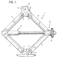
- a lifting jack 1 in the embodiment illustrated by way of example includes a base element 2 for resting on the ground, with two lower arms 5 and 6 pivoted on it at 3 and 4. Two further arms 7 and 8 are pivoted by their lower ends on the upper ends of the arms 5 and 6. The upper ends of the arms 7 and 8 are pivotally connected at 9 and 10 to a connecting element 11.
- a support bracket 12, intended to be applied to an engagement surface of the car, is connected to the connecting element 11 in ways which will be described in detail later.
- a screw-type control and adjustment device indicated 13 in Figure 1 and of a type which is known per se, is fixed to the pivotal connections between the lower arms 5, 6 and the upper arms 7, 8.
- this device enables the configuration of the articulated parallelogram formed by the arms 5-8 to be adjusted so as to alter the height of the support bracket 12.
- the connecting element 11 has two parallel, facing side portions 11a between which the upper arms 7 and 8 are pivoted.
- the support bracket 12 of Figure 2 has an essentially rectangular flat support surface 12a resting on the top of the connecting element 11.
- a U or V-section channel-shape portion 12b is joined to the flat support surface 12a of the bracket 12 with its concave surface facing upwards. This channel-shaped portion is intended to be engaged with a corresponding rib or fillet on the bottom of a car.
- Two downwardly folded side tongues 12c extend from the shorter sides of the support portion 12a of the bracket 12, with only one being visible in Figure 2.
- These tongues 12c have respective vertically elongate apertures or slots 12d through which extend with clearance the ends of a transverse retaining pin or dowel 15 carried by the connecting element 11.
- This pin or dowel is parallel to the pivot axes between the arms 5-8.
- the pin may be engaged in corresponding apertures in the connecting element or be otherwise fixed thereto, for example by welding.
- the support bracket 12 is pivotable about an axis perpendicular to the pivot axes between the arms 5-8.
- the bracket 12 Owing to the dihedral shape of the top of the connecting element 11, the bracket 12 tends to assume two stable working positions in which its portion 12a rests on the top surface 11b or on the top surface 11c respectively of the connecting element 11 and is able to assume all intermediate positions between these two extreme stable positions.
- FIG. 3 shows a first variant of the invention.
- parts and elements which have already been described have been given the same reference numerals.
- the connecting element 11 has a substantially planar top portion 11b.
- the support bracket 12 has a top portion 12a having a lower arcuate, convex surface 12e resting on the top surface 11b of the connecting element 11.
- the engagement between the internal tongues 12c of the bracket 12 and the pin or dowel 15 is substantially the same as described with reference to Figure 2.
- the support bracket 12 is substantially pivotable about an axis perpendicular to the pivot axes between the arms 5-8.
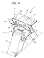
- FIG. 4 shows a further variant of the invention.
- parts and elements which have already been described have been given the same reference numerals.
- the connecting element 11 is substantially identical to that described with reference to Figure 2.
- the support bracket 12 has a planar upper surface resting on the dihedral top portion of the connecting element 11.
- this bracket has no lateral tongues but is pivoted on the connecting element 11 by means of a pin or the like 16 the axis of which is perpendicular to the pivot axes between the arms 5-8.
- the support bracket 12 is once again pivotable about an axis perpendicular to those of the pivotal connections between the aforesaid arms.
Landscapes
- Life Sciences & Earth Sciences (AREA)
- Engineering & Computer Science (AREA)
- Geology (AREA)
- Mechanical Engineering (AREA)
- Structural Engineering (AREA)
- Vehicle Cleaning, Maintenance, Repair, Refitting, And Outriggers (AREA)
- Pivots And Pivotal Connections (AREA)
Applications Claiming Priority (2)
| Application Number | Priority Date | Filing Date | Title |
|---|---|---|---|
| IT95TO000427A IT1279749B1 (it) | 1995-05-26 | 1995-05-26 | Martinetto di sollevamento per un autoveicolo. |
| ITTO950427 | 1995-05-26 |
Publications (1)
| Publication Number | Publication Date |
|---|---|
| EP0744375A1 true EP0744375A1 (en) | 1996-11-27 |
Family
ID=11413593
Family Applications (1)
| Application Number | Title | Priority Date | Filing Date |
|---|---|---|---|
| EP96108252A Withdrawn EP0744375A1 (en) | 1995-05-26 | 1996-05-23 | A lifting jack for a car |
Country Status (2)
| Country | Link |
|---|---|
| EP (1) | EP0744375A1 (it) |
| IT (1) | IT1279749B1 (it) |
Cited By (5)
| Publication number | Priority date | Publication date | Assignee | Title |
|---|---|---|---|---|
| KR100578574B1 (ko) | 2004-06-01 | 2006-05-12 | 기아자동차주식회사 | 기계식 잭의 거치대 기울임장치 |
| WO2010056218A1 (en) * | 2008-11-11 | 2010-05-20 | Arikan Kriko Ve Makina Sanayi Ticaret Anonim Sirketi | Load support for a jack, having bended parts |
| CN103130146A (zh) * | 2013-03-06 | 2013-06-05 | 宁波天益齿轴齿轮有限公司 | 一种支撑臂可分开的千斤顶 |
| CN110040648A (zh) * | 2018-01-15 | 2019-07-23 | 福特环球技术公司 | 剪式千斤顶 |
| CN114195038A (zh) * | 2021-12-16 | 2022-03-18 | 孙岩 | 一种汽车维修用液压提升紧固装置及其使用方法 |
Citations (6)
| Publication number | Priority date | Publication date | Assignee | Title |
|---|---|---|---|---|
| US2672243A (en) * | 1951-10-17 | 1954-03-16 | Ben Goldberg | Jack with adjustable load-receiving table |
| DE3724113A1 (de) * | 1986-12-09 | 1988-06-16 | Tub Sa | Mechanischer heber zum heben von automobilen |
| EP0469234A1 (fr) * | 1990-07-30 | 1992-02-05 | Tub S.A. | Vérin mécanique perfectionné pour des véhicules automobiles |
| EP0529355A1 (de) * | 1991-08-22 | 1993-03-03 | AUGUST BILSTEIN GMBH & CO. KG | Wagenheber |
| EP0622329A1 (en) * | 1993-03-30 | 1994-11-02 | Tub S.A. | Automatic stabilizing and reinforcing device for vehicle raising jacks |
| DE9418720U1 (de) * | 1994-11-24 | 1995-01-12 | Panne GmbH & Co KG Grundstücksgesellschaft, 35753 Greifenstein | Wagenheber für Kfz. |
-
1995
- 1995-05-26 IT IT95TO000427A patent/IT1279749B1/it active IP Right Grant
-
1996
- 1996-05-23 EP EP96108252A patent/EP0744375A1/en not_active Withdrawn
Patent Citations (6)
| Publication number | Priority date | Publication date | Assignee | Title |
|---|---|---|---|---|
| US2672243A (en) * | 1951-10-17 | 1954-03-16 | Ben Goldberg | Jack with adjustable load-receiving table |
| DE3724113A1 (de) * | 1986-12-09 | 1988-06-16 | Tub Sa | Mechanischer heber zum heben von automobilen |
| EP0469234A1 (fr) * | 1990-07-30 | 1992-02-05 | Tub S.A. | Vérin mécanique perfectionné pour des véhicules automobiles |
| EP0529355A1 (de) * | 1991-08-22 | 1993-03-03 | AUGUST BILSTEIN GMBH & CO. KG | Wagenheber |
| EP0622329A1 (en) * | 1993-03-30 | 1994-11-02 | Tub S.A. | Automatic stabilizing and reinforcing device for vehicle raising jacks |
| DE9418720U1 (de) * | 1994-11-24 | 1995-01-12 | Panne GmbH & Co KG Grundstücksgesellschaft, 35753 Greifenstein | Wagenheber für Kfz. |
Cited By (7)
| Publication number | Priority date | Publication date | Assignee | Title |
|---|---|---|---|---|
| KR100578574B1 (ko) | 2004-06-01 | 2006-05-12 | 기아자동차주식회사 | 기계식 잭의 거치대 기울임장치 |
| WO2010056218A1 (en) * | 2008-11-11 | 2010-05-20 | Arikan Kriko Ve Makina Sanayi Ticaret Anonim Sirketi | Load support for a jack, having bended parts |
| US8579258B2 (en) | 2008-11-11 | 2013-11-12 | Arikan Kriko Ve Makina Sanayi Ticaret Anonim Sirketi | Integral load support for a jack formed of a sheet material bent to less than 180° |
| CN103130146A (zh) * | 2013-03-06 | 2013-06-05 | 宁波天益齿轴齿轮有限公司 | 一种支撑臂可分开的千斤顶 |
| CN110040648A (zh) * | 2018-01-15 | 2019-07-23 | 福特环球技术公司 | 剪式千斤顶 |
| CN114195038A (zh) * | 2021-12-16 | 2022-03-18 | 孙岩 | 一种汽车维修用液压提升紧固装置及其使用方法 |
| CN114195038B (zh) * | 2021-12-16 | 2023-08-08 | 孙岩 | 一种汽车维修用液压提升紧固装置及其使用方法 |
Also Published As
| Publication number | Publication date |
|---|---|
| IT1279749B1 (it) | 1997-12-16 |
| ITTO950427A1 (it) | 1996-11-26 |
| ITTO950427A0 (it) | 1995-05-26 |
Similar Documents
| Publication | Publication Date | Title |
|---|---|---|
| EP1147969B1 (en) | Traveling device | |
| JPH0873194A (ja) | 車両用昇降台装置 | |
| AU744222B2 (en) | A lifting device with a liftable and tiltable platform | |
| JPH09506055A (ja) | フレーム部材の終端部分 | |
| JPH10503990A (ja) | 車両の剛性車軸のための懸架装置 | |
| EP0221911B1 (de) | Wagenheber | |
| EP0744375A1 (en) | A lifting jack for a car | |
| GB2070162A (en) | Folding Wheel Chock | |
| EP0151154B1 (en) | Fifth wheel | |
| CN1116171A (zh) | 作为两车之间过渡装置的可斜对角活动的链式桥 | |
| DE3603311C2 (it) | ||
| US5988594A (en) | Half scissor jack structure | |
| US5697598A (en) | One piece load rest | |
| EP0773186B1 (en) | Improved trunnion for use with a pantograph jack | |
| CA2120191A1 (en) | Stabilizing and reinforcing device for vehicle-raising jacks | |
| EP1340711B1 (en) | Lift apparatus having an articulated double parallelogram boom assembly | |
| EP0822106B1 (en) | Spring carrier arm for a vehicle spring system | |
| DE69215005T2 (de) | Wagenheber | |
| JP2843836B2 (ja) | Z形パンタグラフ | |
| EP0032809A1 (en) | Platform and stop bar assembly | |
| JPH05193896A (ja) | リヤアクスル懸架装置用のシム装置 | |
| JPS5984649A (ja) | 窓ふき | |
| US20020134972A1 (en) | Car jack | |
| JPS5826214Y2 (ja) | オ−バ−ヘツドコンベヤの傾動ハンガ−装置 | |
| JP2516965Y2 (ja) | ワイパブレード |
Legal Events
| Date | Code | Title | Description |
|---|---|---|---|
| PUAI | Public reference made under article 153(3) epc to a published international application that has entered the european phase |
Free format text: ORIGINAL CODE: 0009012 |
|
| AK | Designated contracting states |
Kind code of ref document: A1 Designated state(s): DE ES FR GB SE |
|
| 17P | Request for examination filed |
Effective date: 19970412 |
|
| 17Q | First examination report despatched |
Effective date: 19990408 |
|
| STAA | Information on the status of an ep patent application or granted ep patent |
Free format text: STATUS: THE APPLICATION IS DEEMED TO BE WITHDRAWN |
|
| 18D | Application deemed to be withdrawn |
Effective date: 20000509 |