EP0744583A2 - Stossstrahl-Gefriervorrichtung und Verfahren - Google Patents
Stossstrahl-Gefriervorrichtung und Verfahren Download PDFInfo
- Publication number
- EP0744583A2 EP0744583A2 EP96303571A EP96303571A EP0744583A2 EP 0744583 A2 EP0744583 A2 EP 0744583A2 EP 96303571 A EP96303571 A EP 96303571A EP 96303571 A EP96303571 A EP 96303571A EP 0744583 A2 EP0744583 A2 EP 0744583A2
- Authority
- EP
- European Patent Office
- Prior art keywords
- impingement
- refrigerant
- articles
- outlet
- inlet
- Prior art date
- Legal status (The legal status is an assumption and is not a legal conclusion. Google has not performed a legal analysis and makes no representation as to the accuracy of the status listed.)
- Withdrawn
Links
- 238000000034 method Methods 0.000 title claims description 6
- 239000003507 refrigerant Substances 0.000 claims abstract description 118
- 238000007710 freezing Methods 0.000 claims abstract description 43
- 230000008014 freezing Effects 0.000 claims abstract description 43
- 230000008016 vaporization Effects 0.000 claims abstract description 22
- 238000012546 transfer Methods 0.000 claims abstract description 20
- 238000009834 vaporization Methods 0.000 claims abstract description 16
- 239000000203 mixture Substances 0.000 claims description 14
- 238000007599 discharging Methods 0.000 claims description 13
- 239000006200 vaporizer Substances 0.000 claims description 6
- 238000004891 communication Methods 0.000 claims description 5
- 238000005057 refrigeration Methods 0.000 claims description 3
- 238000001816 cooling Methods 0.000 abstract description 3
- IJGRMHOSHXDMSA-UHFFFAOYSA-N Atomic nitrogen Chemical compound N#N IJGRMHOSHXDMSA-UHFFFAOYSA-N 0.000 description 18
- 239000007788 liquid Substances 0.000 description 12
- 229910052757 nitrogen Inorganic materials 0.000 description 9
- 239000007789 gas Substances 0.000 description 4
- 238000004513 sizing Methods 0.000 description 4
- 238000013461 design Methods 0.000 description 3
- 238000005192 partition Methods 0.000 description 2
- 230000000153 supplemental effect Effects 0.000 description 2
- 238000009825 accumulation Methods 0.000 description 1
- 238000007792 addition Methods 0.000 description 1
- 230000001276 controlling effect Effects 0.000 description 1
- 230000000694 effects Effects 0.000 description 1
- 239000012530 fluid Substances 0.000 description 1
- 238000012423 maintenance Methods 0.000 description 1
- 230000001105 regulatory effect Effects 0.000 description 1
- 238000013022 venting Methods 0.000 description 1
Images

Classifications
-
- F—MECHANICAL ENGINEERING; LIGHTING; HEATING; WEAPONS; BLASTING
- F25—REFRIGERATION OR COOLING; COMBINED HEATING AND REFRIGERATION SYSTEMS; HEAT PUMP SYSTEMS; MANUFACTURE OR STORAGE OF ICE; LIQUEFACTION SOLIDIFICATION OF GASES
- F25D—REFRIGERATORS; COLD ROOMS; ICE-BOXES; COOLING OR FREEZING APPARATUS NOT OTHERWISE PROVIDED FOR
- F25D3/00—Devices using other cold materials; Devices using cold-storage bodies
- F25D3/10—Devices using other cold materials; Devices using cold-storage bodies using liquefied gases, e.g. liquid air
- F25D3/11—Devices using other cold materials; Devices using cold-storage bodies using liquefied gases, e.g. liquid air with conveyors carrying articles to be cooled through the cooling space
-
- F—MECHANICAL ENGINEERING; LIGHTING; HEATING; WEAPONS; BLASTING
- F25—REFRIGERATION OR COOLING; COMBINED HEATING AND REFRIGERATION SYSTEMS; HEAT PUMP SYSTEMS; MANUFACTURE OR STORAGE OF ICE; LIQUEFACTION SOLIDIFICATION OF GASES
- F25B—REFRIGERATION MACHINES, PLANTS OR SYSTEMS; COMBINED HEATING AND REFRIGERATION SYSTEMS; HEAT PUMP SYSTEMS
- F25B19/00—Machines, plants or systems, using evaporation of a refrigerant but without recovery of the vapour
Definitions
- the present invention relates to an impingement freezer and freezing method in which jets of refrigerant are directed against articles within a freezing chamber. More particularly, the present invention relates to such an impingement freezer in which the freezing chamber has freezing zones in which the mass flow rates of the impingement jets produced in each of the zones can be adjusted independently of the mass flow rates of the impingement jets in the other remaining zones.
- freezers operate by direct heat transfer from articles to be refrigerated or frozen to a refrigerant such as cooled air or a vaporized liquified gas, for instance, vaporized liquid nitrogen.
- a refrigerant such as cooled air or a vaporized liquified gas, for instance, vaporized liquid nitrogen.
- a freezing chamber or tunnel through which the articles to be refrigerated are conveyed by a conveyor belt.
- cold gaseous nitrogen is circulated throughout the length of the freezing chamber by means of fans.
- impingement jet freezers In order to minimize the thickness of such boundary layer and therefore optimize the utilization of the refrigerant, impingement jet freezers have been developed such as illustrated in European Patent Application 0 612 966A1. In impingement jet freezers, jets of the refrigerant impinge on the articles. These impingement jets are formed by allowing a pressured refrigerant to escape from impingement jet openings formed between a plurality of parallel, elongated channel-like members.
- the forced convective flow that is directed through the impingement openings produces multiple columns of high velocity gas jets that impinge in a perpendicular direction to the product surface. In this manner, high heat transfer coefficients are possible in the stagnation region near the impingement points.
- multiple impingement jets are utilized in such a fashion that a large number of impingement flow cells are created producing relatively thin thermal boundary layers.
- the present invention provides an impingement jet freezer in which the temperature and convective heat transfer coefficient profiles are controllable within the freezer to more efficiently utilize the refrigerant. Moreover, efficiencies are realized by preferred embodiments that do not utilize thermal loading devices such as motorized fans or blowers.
- the present invention provides an impingement freezer comprising a freezing chamber having an inlet for receiving articles to be refrigerated, an outlet for discharging the articles after having been refrigerated.
- a means is provided for conveying articles from the inlet to the outlet and at least two zones are provided that include an inlet zone located adjacent the inlet and an outlet zone located adjacent the outlet. Each of the at least two zones have impingement nozzle means for directing at least one refrigerant jet against the articles to be refrigerated.
- a circulation means is connected to the impingement nozzle means for drawing the refrigerant from the freezing chamber after having exchanged heat with the articles into a mixture with the incoming refrigerant and for discharging the mixture into the impingement nozzle means.
- the circulation means is driven by the at least partially vaporized incoming refrigerant.
- a control means is provided for independently controlling flow rate of the incoming refrigerant to the circulation means of said at least two zones.
- a vaporizer means is positioned within the freezing chamber to exchange heat between the incoming refrigerant and the refrigerant drawn by said circulation means of at least one of the two zones for at least partially vaporizing the incoming refrigerant.
- a distribution means is connected to the vaporization means and the control means for distributing the incoming refrigerant from the vaporization means to the control means.
- a method of refrigerating articles in which the articles are passed through a freezing chamber in a direction taken from the inlet to the outlet of the freezing chamber. Impingement jets of refrigerant are directed against the articles so that the refrigerant warms to form heated refrigerant and the articles cool through direct heat transfer between the refrigerant and the articles.
- the impingement jets are directed against the articles within at least two zones of the refrigeration chamber. The at least two zones include an inlet zone located adjacent to the inlet of the freezing chamber and an outlet zone adjacent to the outlet of the freezer.
- the incoming refrigerant is at least partially vaporized through heat transfer with the heated refrigerant and first and second portions of the incoming refrigerant, after having been at least partially vaporized, are delivered to the outlet and inlet zones, respectively.
- the heated refrigerant is drawn from the inlet and outlet zones by expending work from the at least partly vaporized incoming refrigerant.
- the heated refrigerant is mixed with the first and second portions of the incoming refrigerant.
- the impingement jets of the outlet and inlet zones are formed from mixtures of the heated refrigerant and the first and second portions of the incoming refrigerant, respectively.
- the present invention provides an impingement freezer comprising a freezing chamber having an inlet for receiving articles to be refrigerated and an outlet for discharging the articles after having been refrigerated.
- a means is provided for conveying the articles from the inlet to the outlet.
- At least a first plurality of impingement nozzles are provided for directing refrigerant jets against the articles to be refrigerated.
- At least one ejector is provided having a high pressure inlet for receiving the incoming refrigerant stream, a low pressure inlet for drawing the refrigerant from the freezing chamber after having exchanged heat with the articles into a mixture with the incoming refrigerant, and a high pressure outlet for discharging the mixture into the impingement nozzle.
- a vaporization means is in communication with the high pressure inlet of the at least one ejector for at least partially vaporizing the incoming refrigerant and for discharging the incoming refrigerant to the ejector.
- the vaporization means is positioned within the freezing chamber between the articles and the low pressure inlet so that the refrigerant after having cooled the articles and having itself become heated, transfers heat to the incoming refrigerant before being drawn into the mixture.
- an advantage of the present inventions set forth in the first two aspects mentioned above is that the mass flow rate of incoming refrigerant to each zone can be or is regulated or controlled. This in turn allows for control of the convective heat transfer coefficient of each zone and therefore the degree of refrigeration imparted to each zone.
- an impingement freezer in accordance with the present invention can be operated in a mode in which a cryogenic refrigerant enters a vaporizer within the outlet zone and during vaporization passes in a heat exchanger toward the inlet zone or counter-currently to the articles to be frozen.
- one efficiency realized in any embodiment constructed or operated in accordance with the present invention is that such vaporization occurs within the freezing chamber so that there is no loss in cooling potential in vaporizing incoming refrigerant, for instance, a liquid cryogen such as liquid air, nitrogen or other liquefied atmospheric gas.
- a vaporization could be conducted in a series of vaporizers located in the zones of the freezer which would thereby be amenable to be operated with the outlet zone having the lowest temperature and with temperatures increasing in each succeeding zone towards the inlet zone.
- the inlet zone is not provided with a vaporizer to produce still even warmer temperatures in the inlet zone, where the exhaust would be located.
- a typical counterflow temperature profile can be set up within an impingement freezer of the present invention in which the coldest temperatures are located at the outlet of the freezer and the warmest temperatures located at the inlet of the freezer.
- the temperature of a refrigerant such as liquid nitrogen vaporized within the freezer when vented or exhausted will be greater than in prior art designs to allow for a more efficient usage of the refrigerant.
- the amount of refrigerant entering each zone can be balanced with greater mass flow rates of refrigerant to the impingement nozzles at the inlet end of the freezer as compared with the outlet end of the freezer.
- the heat transfer coefficients can be maximized at the warmest temperatures to produce acceptable freezing rates.
- the last mentioned aspect of the present invention calls for the use of ejectors. It is to be noted that the present invention, in other aspects, also encompasses the use of other venturi-like devices known in the art. This further enhances thermal efficiency of an impingement jet freezer in accordance with the present invention by utilizing the thermal energy of the articles to be refrigerated to drive the convective flow and thereby eliminate the additional heat load due to the work of fans or blowers. It is to be noted that the present invention contemplates the use of supplemental fans or blowers. In such case the use of ejectors or other venturi-like devices will reduce the potential heat load.
- the present invention provides an impingement freezer comprising a freezing chamber having an inlet for receiving articles to be refrigerated, an outlet for discharging the articles after having been refrigerated.
- a means is provided for conveying articles from the inlet to the outlet.
- a plurality of nozzles are provided for directing jets of refrigerant against an article to be refrigerated within an impingement jet freezer.
- a nozzle in accordance with the present invention comprises an elongated body having a proximal end and a distal end located opposite the proximal end.
- the elongated body is tapered in two transverse, cross-sectional orthogonal directions from the proximal end to the distal end. This two dimensional tapering of the nozzle acts to inhibit frost build-up and accumulation.
- refrigerate means to cool articles.
- the term includes anything from a temperature drop to a complete freezing of the articles.
- refrigerant as used herein and in the claims includes cryogenic refrigerants formed from any liquefied atmospheric gas or liquid air itself.
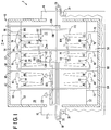
- Impingement jet freezer 1 is provided with a freezing chamber 10 having an inlet 12 for receiving articles to be refrigerated and an outlet 14 for discharging the articles after having been refrigerated.
- An open portion 16 of the entry vestibule of impingement jet freezer 1 is provided for venting refrigerant that has been used in freezing the articles.
- a porous conveyor belt 18 conveys the articles from inlet 12 to outlet 14.
- Porous conveyor belt 18 is mounted on rollers 20 that are motorized to impart motion to porous conveyor belt 18.
- Impingement jet freezer 1 has three zones which include an outlet zone 22 adjacent outlet 14 and intermediate zone 24 adjacent outlet zone 22 and an inlet zone 26 adjacent the inlet zone so that intermediate zone 24 is situated between outlet zone 22 and inlet zone 26.
- an impingement jet freezer in accordance with the present invention could have, at minimum, two zones or could have more than three zones.
- Outlet zone 22 has two rows of upper impingement jet nozzles 28 and 29 and two lower rows of lower impingement jet nozzles 30 and 32. As can be appreciated, larger freezers would employ more rows of impingement jet nozzles.
- Intermediate zone 24 similarly has two rows of upper impingement jet nozzles 34 and 36 and two rows of lower impingement jet nozzles 38 and 40.
- inlet zone 26 has two rows of upper impingement jet nozzles 42 and 44 and two rows of lower impingement jet nozzles 46 and 48.
- the aforementioned upper and lower rows of impingement jet nozzles 28-48 are respectively connected to upper and lower baffle plates 50 and 52.
- Freezing chamber 10 in spaces located above upper baffle plates 50 and below lower baffle plates 52 are further subdivided into three sets of upper and lower compartments associated with outlet, intermediate, and entry zones 22-26. These upper and lower compartments are respectively designated by reference numerals 54, 56; 58, 60; and 62, 64. Upper compartments 54, 58 and 62 are defined between partitions 66 through 69 and lower compartments 56, 60 and 64 are defined between partitions 70 through 73. Refrigerant is introduced into compartments 54-64 and therefore impingement nozzles 28-48 to direct impingement jets against articles being carried through freezing chamber 10 upon conveyor belt 18.
- compartments 54-64 Mounted within compartments 54-64 are upper and lower ejectors 74 and 76 associated with outlet zone 22, upper and lower ejectors 78 and 80 associated with intermediate zone 24, and upper and lower ejectors 82 and 84 associated with inlet zone 26.
- Ejectors 74-84 are mounted within respective compartments 54-64 and are connected to upper and lower baffle plates 50-52 via their low pressure inlets 86 through 96, respectively.
- Each of the ejectors 74-84 are also provided with a high pressure inlet 98 such as illustrated for ejector 74 and high pressure outlet 100 such as also illustrated for ejector 74.
- each ejector through its high pressure outlet introduces refrigerant at a high pressure into compartments 54-64.
- This is turn causes impingement jets to be formed within impingement jet nozzles 28-48 which are in turn directed against the articles to be refrigerated.
- the refrigerant After the refrigerant has cooled the article and has itself become heated to form heated refrigerant, it is drawn into low pressure inlet 86 such as illustrated for ejector 74 to mix with incoming refrigerant. This mixture is used to form the impingement jets of outlet zone 22.
- outlet, intermediate and inlet zones 22-26 are not isolated from one another, the heated refrigerant can also drift in a counter-current direction taken from outlet zone 22 to inlet zone 26 and as such, some heated refrigerant drawn in any zone to any ejector thereof will not have originated in the particular zone under consideration.
- the present invention is not limited to the use of ejectors. For instance, other venturi-like devices could be applicable as well as supplemental fans or blowers.
- the incoming refrigerant which is preferably liquid nitrogen, first enters a pair of upper and lower vaporizers 102 and 104.
- Each of the upper and lower vaporizers 102 and 104 are formed from a bundle of six pipes which are connected end to end. Other vaporizer configurations are possible.
- the liquid nitrogen enters an inlet pipe 106 and then flows into upper and lower vaporizers 102 and 104 by way of branch pipes 108 and 110.
- the liquid nitrogen is at least partially vaporized within upper and lower vaporizers 102 and 104, which are associated with outlet zone 22.
- the refrigerant is drawn past upper and lower vaporizers 102 and 104 and into low pressure inlets 86 and 88 of upper and lower ejectors 74 and 76. Thereafter, the incoming refrigerant flows from upper and lower vaporizers 102 and 104, through transfer pipes 112 and 114, into a pair of upper and lower vaporizers 116 and 118 similar in design to upper and lower vaporizers 102 and 104. Upper and lower vaporizers 116 and 118 are associated with intermediate zone 24.
- refrigerant having been expelled as impingement jets and after having heated by the articles is drawn past upper and lower vaporizers 116 and 118 and into low pressure inlets 90 and 92 of upper and lower ejectors 78 and 80.
- the incoming refrigerant then flows to the high pressure inlet of upper and lower pairs of ejectors 74-84 by provision of a common manifold 120.
- the mass flow rate of incoming refrigerant each of the pairs of ejectors is controlled by mass flow control valves 122, 124, and 126.
- valves 122-126 such valves are not the only control of flow of refrigerant to upper and lower pairs of ejectors 74-84.
- a direct control is provided by appropriately sizing the ejectors.
- Valves 122-126 provide a further flow control. It is to be noted that the present invention encompasses a control without valves that is provided by fixed flow restrictions such as orifices or appropriate sizing of ejector nozzles to obtain the desired operational control of mass flow rate of incoming refrigerant. Alternatively, the present invention encompasses the use of valves without any such sizing of orifices or ejectors.
- inlet zone 26 Since inlet zone 26 is not provided with vaporizers, inlet zone 26 operates at the warmest temperature of any of the zones. Hence, the temperature profile is maintained which is at its coldest at outlet 22 and at its warmest at inlet 26 to minimize cryogen usage. Additionally, since the vaporizers are within the freezing chamber there is no loss of cooling capacity of the incoming liquid cryogen.
- the ejectors are sized to produce a preferred flow split in which the greatest mass flow rate occurs within the warmest zone, namely inlet zone 26.
- the impingement jets produced within inlet zone 26 can be formed with the highest velocity and therefore produce the highest heat transfer coefficient.
- independent control of the impingement jet velocities allows the work capacity of the motive flow of incoming refrigerant to be delivered to outlet, intermediate and inlet zones 22-26 such that the overall heat transfer is maximized.
- a higher heat transfer coefficient needs to be obtained in zones having a lower temperature difference between the articles to be refrigerated and the temperature of the particular zone.
- impingement jet nozzle 28 is typical of the configuration of the impingement jet nozzles.
- Impingement jet nozzle 28 has a proximal end 28a at which impingement jet nozzle 28 is attached to upper baffle 50 and an opposed distal end 28b defining a rectangular opening from which the impingement jet issues forth. Both proximal and distal ends 28a and 28b are rectangular.
- impingement jet nozzle 28 narrows in two orthogonal directions between proximal and distal ends 28a and 28b. This two-dimensional tapering of the impingement jet nozzles inhibits ice or frost build-up.
- top and bottom impingement jet nozzles and ejectors are symmetrically arranged in the illustrated embodiment, other embodiments are possible.
- the lower ejectors and impingement nozzles and etc. could be eliminated. Flow in such an embodiment would be reflected off the bottom of the freezer to the articles to be refrigerated.
- the ejectors might be sized differently with respect to their position in the freezer, for instance, the upper ejectors could be larger than the lower ejectors.
Landscapes
- Engineering & Computer Science (AREA)
- Physics & Mathematics (AREA)
- Mechanical Engineering (AREA)
- Thermal Sciences (AREA)
- General Engineering & Computer Science (AREA)
- Chemical & Material Sciences (AREA)
- Combustion & Propulsion (AREA)
- Devices That Are Associated With Refrigeration Equipment (AREA)
Applications Claiming Priority (2)
| Application Number | Priority Date | Filing Date | Title |
|---|---|---|---|
| US449456 | 1995-05-24 | ||
| US08/449,456 US5740678A (en) | 1995-05-24 | 1995-05-24 | Impingement jet freezer and method |
Publications (2)
| Publication Number | Publication Date |
|---|---|
| EP0744583A2 true EP0744583A2 (de) | 1996-11-27 |
| EP0744583A3 EP0744583A3 (de) | 1998-01-14 |
Family
ID=23784234
Family Applications (1)
| Application Number | Title | Priority Date | Filing Date |
|---|---|---|---|
| EP96303571A Withdrawn EP0744583A3 (de) | 1995-05-24 | 1996-05-20 | Stossstrahl-Gefriervorrichtung und Verfahren |
Country Status (9)
| Country | Link |
|---|---|
| US (1) | US5740678A (de) |
| EP (1) | EP0744583A3 (de) |
| KR (1) | KR960041957A (de) |
| CN (1) | CN1160165A (de) |
| AU (1) | AU711891B2 (de) |
| CA (1) | CA2173532C (de) |
| NZ (1) | NZ286455A (de) |
| PL (1) | PL314398A1 (de) |
| ZA (1) | ZA963829B (de) |
Cited By (1)
| Publication number | Priority date | Publication date | Assignee | Title |
|---|---|---|---|---|
| EP1118824A3 (de) * | 2000-01-18 | 2002-01-30 | The Boc Group, Inc. | Gerät zum Kühlen und Gefrieren von Waren |
Families Citing this family (15)
| Publication number | Priority date | Publication date | Assignee | Title |
|---|---|---|---|---|
| US5813237A (en) * | 1997-06-27 | 1998-09-29 | The Boc Group, Inc. | Cryogenic apparatus and method for spraying a cryogen incorporating generation of two phase flow |
| US6062056A (en) * | 1998-02-18 | 2000-05-16 | Tippins Incorporated | Method and apparatus for cooling a steel strip |
| US6334330B2 (en) | 1999-07-26 | 2002-01-01 | Praxair, Inc. | Impingement cooler |
| US6675622B2 (en) | 2001-05-01 | 2004-01-13 | Air Products And Chemicals, Inc. | Process and roll stand for cold rolling of a metal strip |
| US6557367B1 (en) | 2002-03-28 | 2003-05-06 | Praxair Technology, Inc. | Impingement cooler with improved coolant recycle |
| BR0313529A (pt) * | 2002-08-16 | 2005-07-12 | Boc Group Inc | Método e aparelho para congelar crosta superficial de produto alimentìcio |
| US6877327B2 (en) * | 2002-08-20 | 2005-04-12 | The Boc Group, Inc. | Flow enhanced tunnel freezer |
| US6912869B2 (en) | 2003-06-03 | 2005-07-05 | Praxair Technology, Inc. | Helical impingement cooling and heating |
| US7087804B2 (en) * | 2003-06-19 | 2006-08-08 | Chevron U.S.A. Inc. | Use of waste nitrogen from air separation units for blanketing cargo and ballast tanks |
| US7197883B2 (en) * | 2005-05-06 | 2007-04-03 | Praxair Technology, Inc. | Cooling or heating with multi-pass fluid flow |
| US20110179667A1 (en) * | 2009-09-17 | 2011-07-28 | Lee Ron C | Freeze drying system |
| US20130125576A1 (en) * | 2011-11-17 | 2013-05-23 | Michael D. Newman | Freezer apparatus |
| US20190170424A1 (en) * | 2017-12-01 | 2019-06-06 | Shanghai Ocean University | Jet nozzle structure of impact-type freezer |
| CN110424972B (zh) * | 2019-07-19 | 2025-01-21 | 广东华隧建设集团股份有限公司 | 一种泥水盾构盾尾刷更换液氮冻结安全保护装置 |
| CN115218578B (zh) * | 2022-07-25 | 2024-07-02 | 浙江铭元食品科技有限公司 | 用于食品生产的穿梭渐进式液氮速冻系统 |
Family Cites Families (10)
| Publication number | Priority date | Publication date | Assignee | Title |
|---|---|---|---|---|
| US3307366A (en) * | 1965-07-26 | 1967-03-07 | Pullman Inc | Temperature and atmosphere control apparatus and method therefor |
| US3871185A (en) * | 1965-09-15 | 1975-03-18 | Integral Process Syst Inc | Method and apparatus for flash freezing various products |
| US3427820A (en) * | 1966-11-14 | 1969-02-18 | Reliquifier Corp Of America | Cryogenic flash freezing machines |
| US3447336A (en) * | 1967-09-22 | 1969-06-03 | Pullman Inc | Refrigeration arrangement |
| US4373344A (en) * | 1977-05-18 | 1983-02-15 | Airco, Inc. | Methods and apparatus for producing refrigeration |
| US4399658A (en) * | 1978-02-08 | 1983-08-23 | Safeway Stores, Incorporated | Refrigeration system with carbon dioxide injector |
| GB2046421B (en) * | 1979-02-20 | 1983-05-05 | Linde Ag | Spraying system for delivering a liquid cryogenic coolant into an insulated freezing chamber |
| US4344291A (en) * | 1980-04-28 | 1982-08-17 | Liquid Carbonic Corporation | Cryogenic cabinet freezer |
| JPS60152601U (ja) * | 1984-03-15 | 1985-10-11 | 株式会社 ほくさん | 連続式肝臓片凍結装置 |
| US5334406A (en) * | 1993-02-26 | 1994-08-02 | The Boc Group, Inc. | Method and device for transmitting heating or cooling medium to a food product on a moving substrate |
-
1995
- 1995-05-24 US US08/449,456 patent/US5740678A/en not_active Expired - Lifetime
-
1996
- 1996-04-04 CA CA002173532A patent/CA2173532C/en not_active Expired - Fee Related
- 1996-04-26 NZ NZ286455A patent/NZ286455A/en unknown
- 1996-05-14 ZA ZA963829A patent/ZA963829B/xx unknown
- 1996-05-20 EP EP96303571A patent/EP0744583A3/de not_active Withdrawn
- 1996-05-20 CN CN96106659A patent/CN1160165A/zh active Pending
- 1996-05-21 AU AU52426/96A patent/AU711891B2/en not_active Ceased
- 1996-05-23 PL PL96314398A patent/PL314398A1/xx unknown
- 1996-05-23 KR KR1019960017788A patent/KR960041957A/ko not_active Abandoned
Cited By (3)
| Publication number | Priority date | Publication date | Assignee | Title |
|---|---|---|---|---|
| EP1118824A3 (de) * | 2000-01-18 | 2002-01-30 | The Boc Group, Inc. | Gerät zum Kühlen und Gefrieren von Waren |
| US6434950B2 (en) | 2000-01-18 | 2002-08-20 | The Boc Group, Inc. | Modular apparatus for cooling and freezing of a food product on a moving substrate |
| EP1621830A3 (de) * | 2000-01-18 | 2006-02-08 | The Boc Group, Inc. | Gerät zum Kühlen und Gefrieren von Waren |
Also Published As
| Publication number | Publication date |
|---|---|
| PL314398A1 (en) | 1996-11-25 |
| CA2173532A1 (en) | 1996-11-25 |
| NZ286455A (en) | 1998-06-26 |
| AU5242696A (en) | 1996-12-05 |
| AU711891B2 (en) | 1999-10-21 |
| CN1160165A (zh) | 1997-09-24 |
| EP0744583A3 (de) | 1998-01-14 |
| KR960041957A (ko) | 1996-12-19 |
| ZA963829B (en) | 1996-11-21 |
| US5740678A (en) | 1998-04-21 |
| CA2173532C (en) | 1999-08-17 |
Similar Documents
| Publication | Publication Date | Title |
|---|---|---|
| US5740678A (en) | Impingement jet freezer and method | |
| EP0135106B1 (de) | Verfahren zum Gefrieren von Produkten im Kontakt mit der Kühlflüssigkeit und Vorrichtung zur Durchführung des Verfahrens | |
| US5456084A (en) | Cryogenic heat exchange system and freeze dryer | |
| ES2533451T3 (es) | Congelador de túnel con flujo mejorado | |
| EP2176609B1 (de) | Querstromspiralenwärmeübertragungssystem | |
| US20060266058A1 (en) | Ammonia/CO2 refrigeration system, CO2 brine production system for use therein, and ammonia cooling unit incorporating that production system | |
| JPH0814681A (ja) | 高圧一次閉冷凍ループと二次冷凍ループを用いる冷凍装置 | |
| US4333318A (en) | CO2 Freezer | |
| JP3440157B2 (ja) | 食品冷凍用トンネルフリーザ | |
| HU184431B (en) | Island refrigerated display case with air defrost | |
| WO2013062512A1 (en) | Cross-flow spiral heat transfer apparatus with solid belt | |
| JP3588345B2 (ja) | 冷蔵庫の冷気循環装置 | |
| US6622496B2 (en) | External loop nonfreezing heat exchanger | |
| US7197883B2 (en) | Cooling or heating with multi-pass fluid flow | |
| JPH10267444A (ja) | 凍結方法及び装置 | |
| JP4819250B2 (ja) | バッチ式食品凍結装置 | |
| US5462111A (en) | Cooling apparatus | |
| JP7129372B2 (ja) | 冷蔵装置 | |
| JP3801232B2 (ja) | ガスタービンの吸気冷却装置 | |
| JPS581744Y2 (ja) | 液化ガスによる食品凍結装置 | |
| JP3716012B2 (ja) | 液体空気による空気冷却装置 | |
| KR100451343B1 (ko) | 냉장고의 냉기 공급장치 | |
| JPS6229705B2 (de) | ||
| HK40094774A (zh) | 食品冷冻装置和食品处理系统 |
Legal Events
| Date | Code | Title | Description |
|---|---|---|---|
| PUAI | Public reference made under article 153(3) epc to a published international application that has entered the european phase |
Free format text: ORIGINAL CODE: 0009012 |
|
| AK | Designated contracting states |
Kind code of ref document: A2 Designated state(s): BE DE FR GB IT NL SE |
|
| PUAL | Search report despatched |
Free format text: ORIGINAL CODE: 0009013 |
|
| AK | Designated contracting states |
Kind code of ref document: A3 Designated state(s): BE DE FR GB IT NL SE |
|
| 17P | Request for examination filed |
Effective date: 19980626 |
|
| 17Q | First examination report despatched |
Effective date: 20010301 |
|
| STAA | Information on the status of an ep patent application or granted ep patent |
Free format text: STATUS: THE APPLICATION IS DEEMED TO BE WITHDRAWN |
|
| 18D | Application deemed to be withdrawn |
Effective date: 20010912 |