EP0744763A1 - Kompakte flachförmige Leuchtstofflampe und Verfahren zu ihrer Herstellung - Google Patents
Kompakte flachförmige Leuchtstofflampe und Verfahren zu ihrer Herstellung Download PDFInfo
- Publication number
- EP0744763A1 EP0744763A1 EP96104234A EP96104234A EP0744763A1 EP 0744763 A1 EP0744763 A1 EP 0744763A1 EP 96104234 A EP96104234 A EP 96104234A EP 96104234 A EP96104234 A EP 96104234A EP 0744763 A1 EP0744763 A1 EP 0744763A1
- Authority
- EP
- European Patent Office
- Prior art keywords
- cup
- lamp
- channels
- plate
- channel
- Prior art date
- Legal status (The legal status is an assumption and is not a legal conclusion. Google has not performed a legal analysis and makes no representation as to the accuracy of the status listed.)
- Withdrawn
Links
- 238000004519 manufacturing process Methods 0.000 title claims description 9
- OAICVXFJPJFONN-UHFFFAOYSA-N Phosphorus Chemical compound [P] OAICVXFJPJFONN-UHFFFAOYSA-N 0.000 claims abstract description 33
- 239000011521 glass Substances 0.000 claims description 36
- 238000007789 sealing Methods 0.000 claims description 27
- 238000000034 method Methods 0.000 claims description 16
- 238000000576 coating method Methods 0.000 claims description 11
- QSHDDOUJBYECFT-UHFFFAOYSA-N mercury Chemical compound [Hg] QSHDDOUJBYECFT-UHFFFAOYSA-N 0.000 claims description 8
- 239000011248 coating agent Substances 0.000 claims description 7
- 229910052753 mercury Inorganic materials 0.000 claims description 7
- 239000011261 inert gas Substances 0.000 claims description 3
- 238000005192 partition Methods 0.000 claims 1
- 230000005855 radiation Effects 0.000 abstract description 3
- 238000010521 absorption reaction Methods 0.000 abstract description 2
- 239000000463 material Substances 0.000 abstract description 2
- 230000005284 excitation Effects 0.000 abstract 1
- 238000000465 moulding Methods 0.000 description 12
- 238000000137 annealing Methods 0.000 description 5
- 238000000071 blow moulding Methods 0.000 description 4
- 239000007789 gas Substances 0.000 description 4
- 238000005452 bending Methods 0.000 description 3
- 230000008901 benefit Effects 0.000 description 3
- 230000015572 biosynthetic process Effects 0.000 description 3
- 238000010438 heat treatment Methods 0.000 description 3
- 238000012986 modification Methods 0.000 description 3
- 230000004048 modification Effects 0.000 description 3
- VYPSYNLAJGMNEJ-UHFFFAOYSA-N Silicium dioxide Chemical compound O=[Si]=O VYPSYNLAJGMNEJ-UHFFFAOYSA-N 0.000 description 2
- 230000002265 prevention Effects 0.000 description 2
- 238000009420 retrofitting Methods 0.000 description 2
- 230000003213 activating effect Effects 0.000 description 1
- 230000006978 adaptation Effects 0.000 description 1
- WYTGDNHDOZPMIW-RCBQFDQVSA-N alstonine Natural products C1=CC2=C3C=CC=CC3=NC2=C2N1C[C@H]1[C@H](C)OC=C(C(=O)OC)[C@H]1C2 WYTGDNHDOZPMIW-RCBQFDQVSA-N 0.000 description 1
- PNEYBMLMFCGWSK-UHFFFAOYSA-N aluminium oxide Inorganic materials [O-2].[O-2].[O-2].[Al+3].[Al+3] PNEYBMLMFCGWSK-UHFFFAOYSA-N 0.000 description 1
- 230000015556 catabolic process Effects 0.000 description 1
- 230000008859 change Effects 0.000 description 1
- 229910052681 coesite Inorganic materials 0.000 description 1
- 238000010276 construction Methods 0.000 description 1
- 229910052593 corundum Inorganic materials 0.000 description 1
- 229910052906 cristobalite Inorganic materials 0.000 description 1
- 230000003247 decreasing effect Effects 0.000 description 1
- 238000006731 degradation reaction Methods 0.000 description 1
- 230000002542 deteriorative effect Effects 0.000 description 1
- 230000000694 effects Effects 0.000 description 1
- 239000000284 extract Substances 0.000 description 1
- 238000000605 extraction Methods 0.000 description 1
- 239000005357 flat glass Substances 0.000 description 1
- 230000004907 flux Effects 0.000 description 1
- 239000006060 molten glass Substances 0.000 description 1
- 230000002093 peripheral effect Effects 0.000 description 1
- 230000009467 reduction Effects 0.000 description 1
- 239000000377 silicon dioxide Substances 0.000 description 1
- 229910052682 stishovite Inorganic materials 0.000 description 1
- 238000006467 substitution reaction Methods 0.000 description 1
- 230000001629 suppression Effects 0.000 description 1
- 229910052905 tridymite Inorganic materials 0.000 description 1
- 229910001845 yogo sapphire Inorganic materials 0.000 description 1
Images


Classifications
-
- H—ELECTRICITY
- H01—ELECTRIC ELEMENTS
- H01J—ELECTRIC DISCHARGE TUBES OR DISCHARGE LAMPS
- H01J61/00—Gas-discharge or vapour-discharge lamps
- H01J61/02—Details
- H01J61/30—Vessels; Containers
- H01J61/305—Flat vessels or containers
- H01J61/307—Flat vessels or containers with folded elongated discharge path
-
- Y—GENERAL TAGGING OF NEW TECHNOLOGICAL DEVELOPMENTS; GENERAL TAGGING OF CROSS-SECTIONAL TECHNOLOGIES SPANNING OVER SEVERAL SECTIONS OF THE IPC; TECHNICAL SUBJECTS COVERED BY FORMER USPC CROSS-REFERENCE ART COLLECTIONS [XRACs] AND DIGESTS
- Y02—TECHNOLOGIES OR APPLICATIONS FOR MITIGATION OR ADAPTATION AGAINST CLIMATE CHANGE
- Y02B—CLIMATE CHANGE MITIGATION TECHNOLOGIES RELATED TO BUILDINGS, e.g. HOUSING, HOUSE APPLIANCES OR RELATED END-USER APPLICATIONS
- Y02B20/00—Energy efficient lighting technologies, e.g. halogen lamps or gas discharge lamps
Definitions
- the present invention relates to a method of manufacturing a substantially flat compact fluorescent lamp with increased efficiency.
- the traditional incandescent lamp (IL) generates a luminous flux of, typically, 16 lumens for an input electrical energy of 1 watt and has a life-span of about 750 hours.
- a compact fluorescent lamp (CFL) is approximately 4 times energy efficient and has a life anywhere from 6000 to 10,000 hours. Hence compact fluorescent lamps are increasingly being used for the conservation of energy and decrease of the replacement cost.
- compact fluorescent lamp is not without a premium.
- the retrofitting of incandescent lamp involves high degree of compactness for the structure of compact fluorescent lamp.
- Well known techniques of obtaining the compactness are through bending the typical glass tube into (i) circular form (ii) U-shape (iii) double-U (iv) triple-U and (v) quadruple-U.
- the arc-length needs to be increased to obtain high light output.
- the above complicated bending makes it difficult to maintain high degree of compactness and enhanced arc-length to achieve high light output.
- the compact fluorescent lamps tend to be long necessitating external fixtures if these lamps are to be employed for preferential directional lighting.
- U.S. Patent No. 3,226,590 to Christy employed a large area substantially flat fluorescent lamp called the "panel lamp” that consisted of two corrugated glass plates laid over each other and sealed to withstand the atmospheric pressure by virtue of its corrugation and seal pattern.
- the electrical discharge path was in the shape of a serpentine or labyrinthine channel.
- a similar corrugated structure was adopted for a round substantially flat lamp, as shown in U.S. Patent No. 3,243,630 to W.C. Martyny, with a central hole through which no light was generated.
- An object of the present invention is to provide a cost-effective and substantially flat compact fluorescent lamp and a manufacturing method thereof overcoming the above difficulties.
- a substantially flat lamp according to the invention comprises a glass or glass-like cup, containing channels with side walls inclined at an obtuse angle to a top surface of the side walls, and a cover plate being hermetically sealed to the cup only at a periphery of the cover plate such that a gap between the cover plate and top surfaces of the side walls is minimized to suppress radial discharge across the channels when the lamp is in regular operation.
- a space between the cup and the cover plate being filled with inert gas.
- a phosphor layer is formed on internal surfaces of the channels, and two electron-emissive electrodes provided at two holes through the cup into the channels and sealing the holes.
- the glass molded part comprises concentric channels with gas between its side walls and its top surface finely ground to be in physical contact with the plate sealed to the molded part such that these areas of physical contact do not pass electrical discharge across them.
- the invention provides a substantially flat light source with high brightness and uniform intensity across a front surface for use in applications where brightness uniformity is highly desirable.
- the generated visible light is extracted from the lamp by the proper design of the angle of the walls of the molded part of the lamp. The angle of the channel walls is adjusted to yield optimum light distribution and efficiency.
- the substantially flat compact fluorescent lamp is based on a glass-molding technique.
- a main starting blank for the manufacture of the lamp resembles a cup with channels formed by glass molding technique. These channels run continuously from a periphery to a center with side walls of the blank dispose at a range of preferred angles to the bottom. The top surface of the channel walls are finely ground with all the internal surfaces of the cup being coated with a reflective coating followed by a light-emissive coating, such as phosphor.
- Two electron-emissive electrodes are provided. On of them is integrated to a flare with an exhaust tubulation which embraces a mercury dispenser integral with a getter ring.
- the other with only the flare is integrated with the end opposite to the electrode closed, is sealed into the two holes integral with the molded cup at peripheral and the central locations such that the electrode with the exhaust tabulation occupies the central hole for stability during the subsequent processing of the lamp.
- the electrodes are disposed deep into the holes, for generation of light of equal intensity as the surrounding, over the electrode regions. This results in the formation of positive column over the electrodes when viewed end on and thus reduces the dimness usually encountered in the region in close proximity to the electrodes.
- a circular glass plate is provided in conformity with the outer diameter of the said processed molded cup.
- the plate is coated with a thin layer of phosphor, laid flat on the ground surface of the cup and sealed to the cup after preferentially removing the phosphor layer in the region of sealing such that the surface of the circular plate with its phosphor layer physically touches the ground surfaces of the cup.
- a space between the cup and the plate is evacuated through the exhaust tubulation and filled with a buffer gas after activating the electron-emissive electrodes.
- a mercury dispenser integral with a getter, is activated, the mercury is dispensed into an active region between the electrodes, and the lamp is aged and stabilized.
- Fig. 1 is an isometric view of a molded glass or glass-like cup 11, containing electron-emissive electrodes 14, illustrating disposition of concentric channels 17 and the slope of side walls 23 of the channels, omitting internal coatings for clarity. Top surfaces 27 of the channel walls are finely ground.
- the channels 17 shown in Fig. 1 are a continuously running spiral channel, they may be a plurality of channels parallel to each other.
- Fig. 2 shows an overall construction of a fully assembled substantially flat compact fluorescent lamp 100 according to the present invention.
- the present invention is related to the substantially flat compact fluorescent lamp disclosed in the U.S. Patent Application No. 28/17194, assigned to the assignee of the present application.
- an assembled lamp 100 has a molded glass cup 11 which contains an internally coated concentric channel 17.
- (Details of the channel 17 are shown better in Figs. 1, 4 and 5, and internal coating is shown in Fig. 3.)
- Two holes 30 (refer to Figs. 4 and 5) into the channel 17 are sealed by two electron emissive electrodes 14 which have external leads 13.
- An exhaust tubulation integral with the electrode 14 at the central channel houses a getter and mercury dispenser 19 and is sealed off at a position 20 after the lamp has been subjected to a vacuum exhaust processing.
- a clearance 16 between the circular plate 12 and the top surface 27 (refer to Figs. 1 and 4) of the channel wall is less than 0.001".
- the clearance 16 between the circular plate 12 and the top surfaces 27 of the side walls is sufficient to prevent radial electrical discharge across the channels, except the periphery.
- the height 15 of the assembly from the bottom of the circumferential electrode seal to the top of the circular plate 12 is 0.94", whereas a similar dimension from the bottom of the central electrode seal is 1.13".
- the portion of the plate 12 in contact with the top surfaces 27 of the channels and the surfaces of the channels can be profiled and molded to give a ball and socket fit to prevent radial electrical discharge across the channels.
- FIG. 3 details of the internal coatings both on the circular glass plate 12 and on the molded glass cup 11 facing the channel 17 are illustrated in cross-section for one channel.
- the circular glass plate 12 has a phosphor layer 21 on the side facing the channel 17, and the molded glass cup has another phosphor layer 21 followed by a reflective layer 22 formed on the internal surface of the channel 17.
- the phosphor layer 21 on the plate 12 has a spiral pattern conforming to the topology of the spiral channel 17 on the molded glass cup 11.
- the phosphor layer on the plate 12 is constructed to suppress radial discharge across the channels 17 by way of its proximity or contact with the top surfaces of the channel walls.
- the color of the phosphor layer 21 on the plate 12 may be different among a plurality of portions thereof along the channel.
- Fig. 4 is a cross-sectional view of the molded glass cup containing two holes 30 for sealing the electron-emissive electrodes and the concentric channel 17 for electrical discharge to run from one electrode (not shown) to the other (not shown).
- the channel width at the top surface 27 is 0.42", and the channel height is 0.4".
- a flared edge 29 is another part of the molded cup for ease of sealing to the top circular glass plate 12 by flame sealing technique.
- Fig. 5 is a top open end view of Fig. 4, depicting the continuity of the channel 17 with the two holes 30, one at the center and the other at the periphery of the molded cup, and in a preferred structure the diameter of the holes 30 is 0.5".
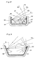
- Fig. 6 depicts a cross-sectional view of the electron-emissive electrode 14 sealed into the center channel 17' of the glass molded cup 11 which in turn is sealed to the top circular glass plate 12. Under typical lamp operating conditions the negative glow region 33 is formed over the electrode 14, due to the proximity of the electrode 14 to the top plate 12.
- Fig. 7 shows a modified example with the same cross-section as in Fig. 6, but with an electrode 14 lowered inside the channel 17'. Both positive column 36 and negative glow 33 are formed over the electrode 14, due to an increased distance of the electrode from the top plate 12.
- the two electrodes 14 are sealed to occupy a level sufficiently below the circular plate 12 to create a positive column 36 over the electrodes 14 to increase the brightness over the electrodes 14 and uniform intensity and distribution of light across the face of the lamp when viewed end-on.
- Fig. 8 shows a cross-section of a channel with a side wall 23' being straight and the generation and direction of travel of light upon the incidence of a ultraviolet photon 39 produced in a typical lamp discharge on a phosphor site 38.
- Fig. 8 also shows the Lambertian distribution of generated light at the site 38 with a peak of the distribution occurring in a direction 40 normal to the side wall 23'. Also shown are the rays of light 42, 43, 44 and 45 at different angles to the normal, the scattered rays of light 46, 47, 48, 49, 50, 51 and 53 at a scattering site 52.
- Fig. 9 illustrates a modified example with a similar cross-section to in Fig. 8 but with the side wall 23 of the channel inclined at angle ⁇ .
- the effect of angle ⁇ on the extraction of the generated light and the resulting brightness increase due to the escape of the peak in the Lambertian distribution is evident.
- Fig. 10 shows a two tier structure of the cross section of the substantially flat compact fluorescent lamp employing two molded cups 57 and 58, containing channels 60, two electron emissive electrodes 55 and 56, and a circular plate 54 containing a hole 59 at the center for the electrical discharge to connect the two tiers which are sealed to the circular plate in a region 61.
- a prototype of the lamp made according to the present invention and tested yielded 1500 lumens at 20 W of power with a lamp voltage at 207 V at a lamp current of 120 mA.
- a glass molded cup has the ease of mass manufacturing the lamp, that (ii) angular disposition of the side walls of the channels extracts the generated light more effectively that a straight side wall as illustrated in Figs. 8 and 9, that (iii) the disposition of the electrodes increases the light output on top of the electrodes, that (iv) suppression of radial discharge is achieved by close control over the gap between the top plate and the top surfaces of the molded cup rather than the laborious procedure of sealing the gap, and finally that (v) the whole lamp is flat and compact.
- the number of channels, channel width, channel height and the angle of inclination of the side walls of the channels can be increased or decreased without changing the outer diameter of the molded cup and the circular plate and thus change the lumen package.
- the geometry of the molded part can be changed to derive rectangular, square or oval flat lamps. It is further understood that deviations from the particular sequence of fabrication steps as well as other substitutions are covered by the present invention.
- the angle of inclination of the side walls of the channel may vary from channel to channel or non-uniform within a channel.
- An alternative embodiment of the invention may relocate the electron-emissive electrodes.
- one more tier of this lamp can be integrated to increase the lumen package.
- An example of an increased lumen package is illustrated in Fig. 10.
- two pieces of the same molded cup are employed to construct a two-tier lamp by sealing two cups 57 and 58 to a circular plate 54, containing a central hole 59 for the continuity of electrical discharge from the bottom tier to the top tier, at regions 61.
- the electrical discharge from an electrode 55 goes through the channel 60 at the bottom cup 58, through the central hole 59, through the concentric channel starting from the center to the periphery and finally to another electrode 56.
- the inner surfaces of the lamp is covered with visible and ultraviolet radiation reflecting material, such as Al 2 O 3 , SiO 2 , etc., everywhere except the viewing surfaces.
Landscapes
- Vessels And Coating Films For Discharge Lamps (AREA)
Applications Claiming Priority (2)
| Application Number | Priority Date | Filing Date | Title |
|---|---|---|---|
| US08/452,312 US5717284A (en) | 1995-05-26 | 1995-05-26 | Method of manufacturing substantially flat compact fluorescent lamp |
| US452312 | 1999-12-01 |
Publications (1)
| Publication Number | Publication Date |
|---|---|
| EP0744763A1 true EP0744763A1 (de) | 1996-11-27 |
Family
ID=23796006
Family Applications (1)
| Application Number | Title | Priority Date | Filing Date |
|---|---|---|---|
| EP96104234A Withdrawn EP0744763A1 (de) | 1995-05-26 | 1996-03-16 | Kompakte flachförmige Leuchtstofflampe und Verfahren zu ihrer Herstellung |
Country Status (3)
| Country | Link |
|---|---|
| US (1) | US5717284A (de) |
| EP (1) | EP0744763A1 (de) |
| JP (1) | JPH0982279A (de) |
Cited By (3)
| Publication number | Priority date | Publication date | Assignee | Title |
|---|---|---|---|---|
| EP0790637A3 (de) * | 1996-02-09 | 1997-11-26 | Matsushita Electric Works, Ltd. | Flache Fluoreszenzkompaktlampe mit Unterdrückung von Entladungen zwischen Kanälen |
| DE19734650A1 (de) * | 1997-08-07 | 1999-03-11 | Fraunhofer Ges Forschung | Vorrichtung zur Emission elektromagnetischer Strahlung durch Gasentladung und Verfahren zur Herstellung der Vorrichtung |
| DE102011003427A1 (de) * | 2011-02-01 | 2012-08-02 | Osram Ag | Leuchte mit einer Entladungslampe, welche ein Entladungsgefäß aufweist, das als Flachspirale ausgebildet ist |
Families Citing this family (10)
| Publication number | Priority date | Publication date | Assignee | Title |
|---|---|---|---|---|
| US6559599B1 (en) * | 1998-11-17 | 2003-05-06 | Corning Incorporated | Internally channeled glass envelope with molded edge for affixing attachments |
| US6639351B1 (en) * | 1999-03-19 | 2003-10-28 | Industrial Technologies Research Institute | Planar fluorescent lamp with flat electrodes and method for fabricating |
| KR100367474B1 (ko) * | 2001-06-12 | 2003-01-10 | 그랜드디스플레이 주식회사 | 평판전극을 이용한 네온사인장치 및 하판구조 |
| US7053555B2 (en) * | 2002-11-21 | 2006-05-30 | Matsushita Electric Industrial Co., Ltd. | Arc tube, discharge lamp, and production method of such arc tube, which enables brighter illuminance |
| TW200526406A (en) * | 2003-10-10 | 2005-08-16 | Inventqjaya Sdn Bhd | Self-cleaning window structure |
| US20050093423A1 (en) * | 2003-10-31 | 2005-05-05 | Cull Brian D. | Redundant flat lamp system |
| US7343714B2 (en) * | 2003-11-10 | 2008-03-18 | Philip Zocco | Door light |
| US7030392B2 (en) * | 2003-12-10 | 2006-04-18 | Alex Waluszko | Ultraviolet lighting platform |
| JP2006202668A (ja) * | 2005-01-24 | 2006-08-03 | Toshiba Lighting & Technology Corp | 蛍光ランプ、蛍光ランプ装置及び照明器具 |
| US10900275B2 (en) * | 2019-01-04 | 2021-01-26 | Guardian Glass, LLC | Integrated tube for vacuum insulated glass (VIG) unit evacuation and hermetic sealing, VIG unit including integrated tube, and associated methods |
Citations (10)
| Publication number | Priority date | Publication date | Assignee | Title |
|---|---|---|---|---|
| US2446712A (en) * | 1942-04-13 | 1948-08-10 | Continental Electric Company | Lamp device |
| US2491847A (en) * | 1945-03-21 | 1949-12-20 | Gen Electric | Electric discharge envelope |
| US3226590A (en) * | 1960-11-15 | 1965-12-28 | Gen Electric | Fluorescent panel lamp |
| US3243630A (en) * | 1962-01-02 | 1966-03-29 | Gen Electric | Fluorescent panel lamp faceplate with opaque striping |
| US3728004A (en) * | 1971-06-25 | 1973-04-17 | Gte Sylvania Inc | Method of employing mercury-dispensing getters in fluorescent lamps |
| NL7502047A (en) * | 1974-03-06 | 1975-09-09 | Burroughs Corp | Display panel manufacturing process with sealed base and cover plate - has atmosphere processing hole in baseplate sealed by glass sphere at end |
| US3913999A (en) * | 1972-08-11 | 1975-10-21 | Thorn Electrical Ind Ltd | Manufacturing electric devices having sealed envelopes |
| WO1992002947A1 (en) * | 1990-08-03 | 1992-02-20 | Lynn Judd B | Thin configuration flat form vacuum-sealed envelope |
| JPH06208844A (ja) * | 1993-01-12 | 1994-07-26 | Sanyo Electric Co Ltd | 平面型螢光ランプ |
| EP0698913A2 (de) * | 1994-08-17 | 1996-02-28 | Matsushita Electric Works, Ltd. | Kompakte Leuchtstofflampe |
Family Cites Families (9)
| Publication number | Priority date | Publication date | Assignee | Title |
|---|---|---|---|---|
| US2405518A (en) * | 1945-11-14 | 1946-08-06 | Igor B Polevitzky | Illuminating device |
| US2555749A (en) * | 1947-12-17 | 1951-06-05 | Krefft Hermann Eduard | Fluorescent lamp |
| US3258630A (en) * | 1962-02-09 | 1966-06-28 | Electric discharge lamps | |
| NL7906203A (nl) * | 1979-08-15 | 1981-02-17 | Philips Nv | Lagedrukkwikdampontladingslamp. |
| DE3584635D1 (de) * | 1985-11-21 | 1991-12-12 | Gte Licht Gmbh | Niederdruckbogenentladungslichtquelleneinheit. |
| EP0298544B1 (de) * | 1987-07-09 | 1991-09-04 | Matsushita Electric Works, Ltd. | Farb-Leuchtstofflampen-Anzeigeeinheit |
| US5220249A (en) * | 1990-10-08 | 1993-06-15 | Nec Corporation | Flat type fluorescent lamp and method of lighting |
| US5479071A (en) * | 1993-05-03 | 1995-12-26 | Flat Candle Company | Flat form device for creating illuminated patterns |
| US5479069A (en) * | 1994-02-18 | 1995-12-26 | Winsor Corporation | Planar fluorescent lamp with metal body and serpentine channel |
-
1995
- 1995-05-26 US US08/452,312 patent/US5717284A/en not_active Expired - Fee Related
-
1996
- 1996-01-10 JP JP8002201A patent/JPH0982279A/ja active Pending
- 1996-03-16 EP EP96104234A patent/EP0744763A1/de not_active Withdrawn
Patent Citations (10)
| Publication number | Priority date | Publication date | Assignee | Title |
|---|---|---|---|---|
| US2446712A (en) * | 1942-04-13 | 1948-08-10 | Continental Electric Company | Lamp device |
| US2491847A (en) * | 1945-03-21 | 1949-12-20 | Gen Electric | Electric discharge envelope |
| US3226590A (en) * | 1960-11-15 | 1965-12-28 | Gen Electric | Fluorescent panel lamp |
| US3243630A (en) * | 1962-01-02 | 1966-03-29 | Gen Electric | Fluorescent panel lamp faceplate with opaque striping |
| US3728004A (en) * | 1971-06-25 | 1973-04-17 | Gte Sylvania Inc | Method of employing mercury-dispensing getters in fluorescent lamps |
| US3913999A (en) * | 1972-08-11 | 1975-10-21 | Thorn Electrical Ind Ltd | Manufacturing electric devices having sealed envelopes |
| NL7502047A (en) * | 1974-03-06 | 1975-09-09 | Burroughs Corp | Display panel manufacturing process with sealed base and cover plate - has atmosphere processing hole in baseplate sealed by glass sphere at end |
| WO1992002947A1 (en) * | 1990-08-03 | 1992-02-20 | Lynn Judd B | Thin configuration flat form vacuum-sealed envelope |
| JPH06208844A (ja) * | 1993-01-12 | 1994-07-26 | Sanyo Electric Co Ltd | 平面型螢光ランプ |
| EP0698913A2 (de) * | 1994-08-17 | 1996-02-28 | Matsushita Electric Works, Ltd. | Kompakte Leuchtstofflampe |
Non-Patent Citations (1)
| Title |
|---|
| PATENT ABSTRACTS OF JAPAN vol. 018, no. 566 (E - 1622) 28 October 1994 (1994-10-28) * |
Cited By (4)
| Publication number | Priority date | Publication date | Assignee | Title |
|---|---|---|---|---|
| EP0790637A3 (de) * | 1996-02-09 | 1997-11-26 | Matsushita Electric Works, Ltd. | Flache Fluoreszenzkompaktlampe mit Unterdrückung von Entladungen zwischen Kanälen |
| DE19734650A1 (de) * | 1997-08-07 | 1999-03-11 | Fraunhofer Ges Forschung | Vorrichtung zur Emission elektromagnetischer Strahlung durch Gasentladung und Verfahren zur Herstellung der Vorrichtung |
| DE19734650B4 (de) * | 1997-08-07 | 2007-06-21 | Fraunhofer-Gesellschaft zur Förderung der angewandten Forschung e.V. | Vorrichtung zur Emission elektromagnetischer Strahlung durch Gasentladung, Verfahren zu ihrer Herstellung und Verwendung der Vorrichtung |
| DE102011003427A1 (de) * | 2011-02-01 | 2012-08-02 | Osram Ag | Leuchte mit einer Entladungslampe, welche ein Entladungsgefäß aufweist, das als Flachspirale ausgebildet ist |
Also Published As
| Publication number | Publication date |
|---|---|
| US5717284A (en) | 1998-02-10 |
| JPH0982279A (ja) | 1997-03-28 |
Similar Documents
| Publication | Publication Date | Title |
|---|---|---|
| US5717284A (en) | Method of manufacturing substantially flat compact fluorescent lamp | |
| US7423370B2 (en) | Arc tube with shortened total length, manufacturing method for arc tube, and low-pressure mercury lamp | |
| CA1142153A (en) | Lamp having convoluted fluorescent tube encased in screw based envelope | |
| US5850122A (en) | Fluorescent lamp with external electrode housing and method for making | |
| US5811925A (en) | Integrally molded flat compact fluorescent lamp | |
| US7064488B2 (en) | Easily-assembled compact self-ballasted fluorescent lamp | |
| CN1286143C (zh) | 带螺旋形放电管的放电灯 | |
| EP0790637B1 (de) | Flache Fluoreszenzkompaktlampe mit Unterdrückung von Entladungen zwischen Kanälen | |
| JP3417160B2 (ja) | 無電極放電ランプ | |
| KR20010049899A (ko) | 세라믹 아크 튜브 제조 방법 | |
| US2213245A (en) | Electrical discharge device | |
| EP0720208B1 (de) | Kreisförmige Fluoreszenzlampe | |
| EP0698913B1 (de) | Kompakte Leuchtstofflampe | |
| US7088033B2 (en) | Electrodeless fluorescent lamp with stabilized operation at high and low ambient temperatures | |
| US4475058A (en) | Discharge lamp having convoluted discharge path | |
| KR100352918B1 (ko) | 램프와 램프의 제조방법 | |
| US20200303178A1 (en) | Light irradiation device and flash lamp | |
| US7659657B2 (en) | Flat fluorescent lamp with improved capability of luminance and reduced initial operational voltage | |
| JP2001023568A (ja) | 環形蛍光ランプ | |
| JPH09320522A (ja) | 蛍光ランプ | |
| KR100447900B1 (ko) | 외부공동전극에 의한 방전등 | |
| JPS6347102B2 (de) | ||
| JPS62163251A (ja) | 放電ランプ | |
| KR20050112531A (ko) | 선형태의 방전공간을 가지는 평면램프의 전극구조 및 제작 방법 | |
| JPS5866251A (ja) | 超高出力形螢光ランプ |
Legal Events
| Date | Code | Title | Description |
|---|---|---|---|
| PUAI | Public reference made under article 153(3) epc to a published international application that has entered the european phase |
Free format text: ORIGINAL CODE: 0009012 |
|
| 17P | Request for examination filed |
Effective date: 19960316 |
|
| AK | Designated contracting states |
Kind code of ref document: A1 Designated state(s): DE FR GB NL |
|
| 17Q | First examination report despatched |
Effective date: 19971215 |
|
| RAP1 | Party data changed (applicant data changed or rights of an application transferred) |
Owner name: PANASONIC ELECTRIC WORKS CO., LTD. |
|
| STAA | Information on the status of an ep patent application or granted ep patent |
Free format text: STATUS: THE APPLICATION IS DEEMED TO BE WITHDRAWN |
|
| 18D | Application deemed to be withdrawn |
Effective date: 20111001 |