EP0744801A1 - Vorrichtung mit einer Halbleiterwellenleiterstruktur - Google Patents
Vorrichtung mit einer Halbleiterwellenleiterstruktur Download PDFInfo
- Publication number
- EP0744801A1 EP0744801A1 EP96303409A EP96303409A EP0744801A1 EP 0744801 A1 EP0744801 A1 EP 0744801A1 EP 96303409 A EP96303409 A EP 96303409A EP 96303409 A EP96303409 A EP 96303409A EP 0744801 A1 EP0744801 A1 EP 0744801A1
- Authority
- EP
- European Patent Office
- Prior art keywords
- semiconductor material
- waveguide
- refractive index
- doped
- article
- Prior art date
- Legal status (The legal status is an assumption and is not a legal conclusion. Google has not performed a legal analysis and makes no representation as to the accuracy of the status listed.)
- Granted
Links
Images
Classifications
-
- G—PHYSICS
- G02—OPTICS
- G02B—OPTICAL ELEMENTS, SYSTEMS OR APPARATUS
- G02B6/00—Light guides; Structural details of arrangements comprising light guides and other optical elements, e.g. couplings
- G02B6/10—Light guides; Structural details of arrangements comprising light guides and other optical elements, e.g. couplings of the optical waveguide type
- G02B6/12—Light guides; Structural details of arrangements comprising light guides and other optical elements, e.g. couplings of the optical waveguide type of the integrated circuit kind
- G02B6/122—Basic optical elements, e.g. light-guiding paths
-
- B—PERFORMING OPERATIONS; TRANSPORTING
- B82—NANOTECHNOLOGY
- B82Y—SPECIFIC USES OR APPLICATIONS OF NANOSTRUCTURES; MEASUREMENT OR ANALYSIS OF NANOSTRUCTURES; MANUFACTURE OR TREATMENT OF NANOSTRUCTURES
- B82Y20/00—Nanooptics, e.g. quantum optics or photonic crystals
-
- G—PHYSICS
- G02—OPTICS
- G02B—OPTICAL ELEMENTS, SYSTEMS OR APPARATUS
- G02B6/00—Light guides; Structural details of arrangements comprising light guides and other optical elements, e.g. couplings
- G02B6/10—Light guides; Structural details of arrangements comprising light guides and other optical elements, e.g. couplings of the optical waveguide type
- G02B6/12—Light guides; Structural details of arrangements comprising light guides and other optical elements, e.g. couplings of the optical waveguide type of the integrated circuit kind
- G02B6/122—Basic optical elements, e.g. light-guiding paths
- G02B6/1228—Tapered waveguides, e.g. integrated spot-size transformers
-
- H—ELECTRICITY
- H01—ELECTRIC ELEMENTS
- H01S—DEVICES USING THE PROCESS OF LIGHT AMPLIFICATION BY STIMULATED EMISSION OF RADIATION [LASER] TO AMPLIFY OR GENERATE LIGHT; DEVICES USING STIMULATED EMISSION OF ELECTROMAGNETIC RADIATION IN WAVE RANGES OTHER THAN OPTICAL
- H01S5/00—Semiconductor lasers
- H01S5/20—Structure or shape of the semiconductor body to guide the optical wave ; Confining structures perpendicular to the optical axis, e.g. index or gain guiding, stripe geometry, broad area lasers, gain tailoring, transverse or lateral reflectors, special cladding structures, MQW barrier reflection layers
-
- H—ELECTRICITY
- H01—ELECTRIC ELEMENTS
- H01S—DEVICES USING THE PROCESS OF LIGHT AMPLIFICATION BY STIMULATED EMISSION OF RADIATION [LASER] TO AMPLIFY OR GENERATE LIGHT; DEVICES USING STIMULATED EMISSION OF ELECTROMAGNETIC RADIATION IN WAVE RANGES OTHER THAN OPTICAL
- H01S5/00—Semiconductor lasers
- H01S5/30—Structure or shape of the active region; Materials used for the active region
- H01S5/305—Structure or shape of the active region; Materials used for the active region characterised by the doping materials used in the laser structure
-
- H—ELECTRICITY
- H01—ELECTRIC ELEMENTS
- H01S—DEVICES USING THE PROCESS OF LIGHT AMPLIFICATION BY STIMULATED EMISSION OF RADIATION [LASER] TO AMPLIFY OR GENERATE LIGHT; DEVICES USING STIMULATED EMISSION OF ELECTROMAGNETIC RADIATION IN WAVE RANGES OTHER THAN OPTICAL
- H01S5/00—Semiconductor lasers
- H01S5/20—Structure or shape of the semiconductor body to guide the optical wave ; Confining structures perpendicular to the optical axis, e.g. index or gain guiding, stripe geometry, broad area lasers, gain tailoring, transverse or lateral reflectors, special cladding structures, MQW barrier reflection layers
- H01S5/2004—Confining in the direction perpendicular to the layer structure
-
- H—ELECTRICITY
- H01—ELECTRIC ELEMENTS
- H01S—DEVICES USING THE PROCESS OF LIGHT AMPLIFICATION BY STIMULATED EMISSION OF RADIATION [LASER] TO AMPLIFY OR GENERATE LIGHT; DEVICES USING STIMULATED EMISSION OF ELECTROMAGNETIC RADIATION IN WAVE RANGES OTHER THAN OPTICAL
- H01S5/00—Semiconductor lasers
- H01S5/30—Structure or shape of the active region; Materials used for the active region
- H01S5/32—Structure or shape of the active region; Materials used for the active region comprising PN junctions, e.g. hetero- or double- heterostructures
- H01S5/3211—Structure or shape of the active region; Materials used for the active region comprising PN junctions, e.g. hetero- or double- heterostructures characterised by special cladding layers, e.g. details on band-discontinuities
-
- H—ELECTRICITY
- H01—ELECTRIC ELEMENTS
- H01S—DEVICES USING THE PROCESS OF LIGHT AMPLIFICATION BY STIMULATED EMISSION OF RADIATION [LASER] TO AMPLIFY OR GENERATE LIGHT; DEVICES USING STIMULATED EMISSION OF ELECTROMAGNETIC RADIATION IN WAVE RANGES OTHER THAN OPTICAL
- H01S5/00—Semiconductor lasers
- H01S5/30—Structure or shape of the active region; Materials used for the active region
- H01S5/34—Structure or shape of the active region; Materials used for the active region comprising quantum well or superlattice structures, e.g. single quantum well [SQW] lasers, multiple quantum well [MQW] lasers or graded index separate confinement heterostructure [GRINSCH] lasers
- H01S5/3401—Structure or shape of the active region; Materials used for the active region comprising quantum well or superlattice structures, e.g. single quantum well [SQW] lasers, multiple quantum well [MQW] lasers or graded index separate confinement heterostructure [GRINSCH] lasers having no PN junction, e.g. unipolar lasers, intersubband lasers, quantum cascade lasers
- H01S5/3402—Structure or shape of the active region; Materials used for the active region comprising quantum well or superlattice structures, e.g. single quantum well [SQW] lasers, multiple quantum well [MQW] lasers or graded index separate confinement heterostructure [GRINSCH] lasers having no PN junction, e.g. unipolar lasers, intersubband lasers, quantum cascade lasers intersubband lasers, e.g. transitions within the conduction or valence bands
Definitions
- This invention pertains to a semiconductor waveguide structure, and to articles (e.g., semiconductor lasers or modulators) that comprise the waveguide structure.
- semiconductor waveguide structures are well known.
- semiconductor lasers typically are designed to comprise a waveguide structure that confines the radiation in the direction normal to the plane of the layers.
- Such a structure generally comprises a first and a second cladding region, with a core region between the cladding regions.
- the layer structure of the laser is selected such that the refractive index of the core region is greater than the refractive indices of the first and second cladding regions, respectively.
- the refractive indices of the first and second cladding regions need not be the same.
- Semiconductor waveguide structures can readily be designed and made for conventional III/V devices. Such devices typically have operating wavelengths ⁇ 2 ⁇ m.
- QC quantum cascade
- the QC laser will generally be implemented in III/V technology and can be designed to emit radiation of wavelength substantially longer than that emitted by conventional III/V lasers.
- the above cited paper describes a QC laser that operated at about 4.5 ⁇ m. In principle, QC lasers can operate at even larger wavelengths.
- our initial attempts ⁇ to design a QC laser that emits radiation of wavelength >5 pm revealed the existence of a problem that was, to the best of our knowledge, not previously encountered.
- an exemplary 4.2 ⁇ m QC laser had an upper cladding region consisting of a 1 ⁇ m thick n-doped (1.5x10 17 /cm 3 ) AlInAs layer and a 1.5 ⁇ m n-doped (5x10 17 /cm 3 ) further AlInAs layer, with the total layer structure being of approximate thickness 5 ⁇ m- Deposition of such a relatively thick layer structure by MBE (or other deposition methods, e.g., CBE, that may be suitable for making a precision layer structure such as is required for QC lasers) is time consuming.
- MBE or other deposition methods, e.g., CBE, that may be suitable for making a precision layer structure such as is required for QC lasers
- the required thickness of the cladding layer of a semiconductor waveguide structure generally increases with increasing wavelength. It will also be understood that the presence of a metal contact layer on a cladding layer imposes stringent limits on the permitted strength of the optical field at the metal/semiconductor interface, if losses of the optical field are to be kept to an acceptable level. These considerations point to an impractically large upper cladding layer thickness in QC lasers that emit at wavelengths ⁇ 5 ⁇ m.
- novel waveguiding structure that is suitable for use in long wavelength (typically ⁇ 5 ⁇ m) QC lasers, and that can also be advantageously used in other long-wavelength devices that comprise a semiconductor waveguide structure, e.g., in an optical modulator.
- the novel structure utilizes an effect that was, to the best of our knowledge, not previously relied on in waveguide structures. Use of the effect makes possible structures that have a substantially thinner cladding layer than would be necessary in prior art technology.
- the "plasma frequency" ⁇ p of a doped semiconductor region is a natural mode of oscillation of the carrier "gas” (typically electron gas) in the doped semiconductor.
- the mode is generally referred to as a plasma mode, or plasmon. Excitation of the plasma mode is associated with a singularity in the free carrier contribution to the dielectric constant of the material. Since the plasma frequency of a semiconductor material is a function of the concentration of free charge carriers (typically electrons) in the material, the optical properties of the material depend on the doping level of the semiconductor material.
- the plasma frequency ⁇ p Ne 2 / ⁇ o m, where N, e, ⁇ o and m are, respectively, the free carrier concentration (i.e., the doping level), the electron charge, the vacuum permittivity, and the free carrier effective mass, all in MKS units.
- the invention is defined by the claims. It is embodied in an article (e.g., a QC laser or a semiconductor waveguide modulator) that comprises a novel waveguide structure for radiation of (vacuum) wavelength ⁇ (equivalently, of radial frequency ⁇ ), where ⁇ typically is about 5 ⁇ m or longer.
- the waveguide structure comprises a core region and a cladding region that has refractive index that is less than the refractive index of the core region.
- the cladding region comprises doped semiconductor material having a dopant concentration N and a plasma radial frequency ⁇ p , with N selected such that, for radiation of wavelength ⁇ , the doped semiconductor material has a refractive index that has a real part n ⁇ 0.5 ⁇ 1 ⁇ 2 ⁇ and an imaginary part k ⁇ 1.
- the cladding of waveguides according to the invention comprises relatively highly doped material, exemplarily with dopant concentration N > 10 18 /cm 3 or even ⁇ 5 x 10 18 /cm 3 , substantially higher than concentrations typically used in prior art waveguides.
- the invention can be embodied in any semiconductor material, including in Si and Si-based semiconductors such as Si x Ge 1-x .
- the doped semiconductor material has to be positioned in the optically active part of the cladding.
- Table I shows the layer structure of a QC laser designed to emit radiation of 8.4 ⁇ m wavelength.
- the structure of Tables I and II is lattice matched to InP. This condition determines the layer compositions, as is known to those skilled in the art.
- the "injector" layer of Table I consists of 4 coupled quantum wells which form a pseudo-quaternary alloy simulating a graded gap (see Table II), and the "active region” consists of three GaInAs quantum wells (thickness 5.8, 7.5 and 3.5 nm, respectively), separated by 2 nm thick AlInAs barriers
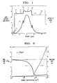
- the 25 injectors/active regions correspond to central core region 11 of the refractive index profile of FIG. 1
- the 700 nm GaInAs layer and the 25 nm InAlGaAs graded layer between the InP substrate and the central core region correspond to outer core region 12
- the 500 nm GaInAs layer and 40 nm graded AlGaInAs layer between the central core region and the upper cladding region correspond to outer core region 13.
- the n InP substrate provides lower cladding region 14.
- the upper cladding layer consists of 6 layers, of which 5 are conventionally doped and correspond to regions 15 and 16 of the refractive index profile of FIG. 1.
- the sixth layer (600 nm thick GaInAs, 7 x 10 18 /cm 3 ) however is not conventional, and is a significant feature of the inventive structure, with the dopant concentration N of layer 17 selected to result in the desired complex refractive index.
- An exemplary procedure for determining the appropriate value of N will now be described.
- ⁇ ⁇ is the high-frequency lattice dielectric constant (essentially corresponding to the dielectric constant of undoped semiconductor material of the relevant composition for infrared radiation), and ⁇ is the electron scattering time.
- the other quantities are as defined above.
- the real and imaginary part of the refractive index can be written respectively as follows:
- N n ⁇ 0.5 ⁇ 1 ⁇ 2 ⁇ , k ⁇ 1.
- n and k are small, e.g., below 0.5 ⁇ 1 ⁇ 2 ⁇ and 1, respectively.
- the highly doped cladding layer according to the invention need not necessarily be the cladding layer that is most remote from the core. However, placement as shown in Table I is preferred because it results in relatively low loss.
- the multilayer semiconductor structure of Table I was grown on a InP substrate by MBE, and processed into mesa-etched 22 ⁇ m wide waveguides by conventional wet chemical etching. This was followed by growth of a 200 nm thick Si 3 N 4 layer to provide insulation between the contact pads and the doped InP substrate. Windows were defined through the Si 3 N 4 by plasma etching, thereby exposing the mesa tops. Ti/Au non-alloyed ohmic contacts were then formed on the mesa tops, followed by cleaving of the processed wafer into bars of different length. Cleaved bars were then soldered with In to a copper holder, wire bonded and tested in a He flow cryostat.
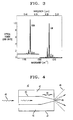
- FIG. 3 shows an exemplary high resolution spectrum of one of the above described QC lasers, taken in rapid scan with a Fourier transform interferometer. Peak optical powers of the lasers ranged from about 50 mW at 10K to about 10 mW at the highest heat-sink temperature (130K). Average slope efficiency was about 0.1 W/A at 100K.
- long wavelength QC lasers are not the only possible embodiments of the invention.
- the invention can be usefully embodied in any device that comprises a semiconductor (not necessarily III/V semiconductor) waveguide for relatively long wavelength (typically ⁇ 5 ⁇ m) radiation, especially for such devices that comprise a metal layer in close proximity to the waveguide (e.g., the metal layer is disposed on the cladding region).
- a semiconductor modulator of the type described in E. B. Dupont et al., IEEE J. of Quantum Electronics , Vol. 29, p. 2313 (1993).
- a tapered core semiconductor waveguide (typically, but not necessarily a planar waveguide) for, e.g., radiation from a CO 2 laser.
- a tapered core semiconductor waveguide typically, but not necessarily a planar waveguide
- Such a structure could be used to concentrate the radiation into a very small ( ⁇ 1 ⁇ m) region at the core/air interface, with the beam being highly divergent in air.
- the power density in the beam is highly position-dependent, with very high power density existing close to the core/air interface, but with relatively low power density elsewhere.
- Apparatus comprising such a tapered waveguide is useful for controlled material modification, including surgery.
- FIG. 4 schematically shows in top view an exemplary structure 40 as described above, with numeral 41 referring to a semiconductor (e.g., Si) body that comprises a planar waveguide with lateral confinement of the radiation obtained by appropriate doping of regions 42, substantially as described above.
- Numeral 43 refers to the core of the waveguide, and 44 refers to the tapered section of the core.
- the guided radiation exits from the guide at 45, forming a highly divergent beam that can have very high power density close to 45.
Landscapes
- Physics & Mathematics (AREA)
- Optics & Photonics (AREA)
- Engineering & Computer Science (AREA)
- General Physics & Mathematics (AREA)
- Electromagnetism (AREA)
- Chemical & Material Sciences (AREA)
- Nanotechnology (AREA)
- Condensed Matter Physics & Semiconductors (AREA)
- Microelectronics & Electronic Packaging (AREA)
- Life Sciences & Earth Sciences (AREA)
- Biophysics (AREA)
- Crystallography & Structural Chemistry (AREA)
- Power Engineering (AREA)
- Geometry (AREA)
- Semiconductor Lasers (AREA)
- Optical Integrated Circuits (AREA)
Applications Claiming Priority (2)
| Application Number | Priority Date | Filing Date | Title |
|---|---|---|---|
| US445821 | 1995-05-22 | ||
| US08/445,821 US5502787A (en) | 1995-05-22 | 1995-05-22 | Article comprising a semiconductor waveguide structure |
Publications (2)
| Publication Number | Publication Date |
|---|---|
| EP0744801A1 true EP0744801A1 (de) | 1996-11-27 |
| EP0744801B1 EP0744801B1 (de) | 2000-09-27 |
Family
ID=23770330
Family Applications (1)
| Application Number | Title | Priority Date | Filing Date |
|---|---|---|---|
| EP96303409A Expired - Lifetime EP0744801B1 (de) | 1995-05-22 | 1996-05-14 | Vorrichtung mit einer Halbleiterwellenleiterstruktur |
Country Status (4)
| Country | Link |
|---|---|
| US (1) | US5502787A (de) |
| EP (1) | EP0744801B1 (de) |
| JP (1) | JP3616194B2 (de) |
| DE (1) | DE69610459T2 (de) |
Families Citing this family (28)
| Publication number | Priority date | Publication date | Assignee | Title |
|---|---|---|---|---|
| US5838868A (en) * | 1995-06-30 | 1998-11-17 | Syracuse University | Semiconductor fiber light amplifier |
| US5936989A (en) * | 1997-04-29 | 1999-08-10 | Lucent Technologies, Inc. | Quantum cascade laser |
| US5978397A (en) * | 1997-03-27 | 1999-11-02 | Lucent Technologies Inc. | Article comprising an electric field-tunable semiconductor laser |
| US5901168A (en) * | 1997-05-07 | 1999-05-04 | Lucent Technologies Inc. | Article comprising an improved QC laser |
| FR2766582A1 (fr) * | 1997-07-23 | 1999-01-29 | Corning Inc | Methode de fabrication de composant optique et composant optique fabrique selon cette methode |
| FR2777358B1 (fr) * | 1998-04-10 | 2000-06-30 | France Telecom | Procede electrooptique de traitement de signaux, dispositif pour la mise en oeuvre de celui-ci et utilisation |
| US6055257A (en) * | 1998-04-27 | 2000-04-25 | Lucent Technologies Inc. | Quantum cascade laser |
| US6091753A (en) * | 1998-05-01 | 2000-07-18 | Lucent Technologies Inc. | Article comprising an improved superlattice quantum cascade laser |
| US6301282B1 (en) | 1998-07-29 | 2001-10-09 | Lucent Technologies Inc. | Long wavelength semiconductor lasers incorporating waveguides based on surface plasmons |
| US6055254A (en) * | 1998-09-23 | 2000-04-25 | Lucent Technologies Inc. | Quantum cascade light emitter with pre-biased internal electronic potential |
| WO2001029544A1 (en) * | 1999-10-15 | 2001-04-26 | Philips Electron Optics | Method of determining the charge carrier concentration in materials, notably semiconductors |
| US6501783B1 (en) | 2000-02-24 | 2002-12-31 | Lucent Technologies Inc. | Distributed feedback surface plasmon laser |
| US6400744B1 (en) | 2000-02-25 | 2002-06-04 | Lucent Technologies, Inc. | Apparatus comprising a quantum cascade laser having improved distributed feedback for single-mode operation |
| US6654533B1 (en) * | 2000-06-16 | 2003-11-25 | Metrophotonics Inc. | Polarization independent waveguide structure |
| FR2834130B1 (fr) * | 2001-12-20 | 2005-02-18 | Thales Sa | Procede d'amelioration des caracteristiques optiques de composants optoelectroniques multicouches |
| ITTO20020274A1 (it) * | 2002-03-27 | 2003-09-29 | Infm Istituto Nazionela Per La | Laser thz a semiconduttore incorporante guida d'onda a confinamento plasmonico controllato. |
| US6836499B2 (en) * | 2002-05-24 | 2004-12-28 | Lucent Technologies Inc. | Optical amplifier for quantum cascade laser |
| US20040109692A1 (en) * | 2002-12-09 | 2004-06-10 | James Plante | FSO communication systems having high performance detectors |
| JP2006309146A (ja) * | 2005-03-31 | 2006-11-09 | Fuji Photo Film Co Ltd | 光源モジュール |
| FR2953335B1 (fr) * | 2009-11-27 | 2012-04-27 | Centre Nat Rech Scient | Systeme d'emission laser, heterostructure et zone active a sous-puits quantiques couples, utilisation pour une emission laser a 1,55 micrometres |
| US8929417B2 (en) | 2009-12-21 | 2015-01-06 | The Board Of Regents Of The University Of Oklahoma | Semiconductor interband lasers and method of forming |
| JP6107662B2 (ja) * | 2011-11-30 | 2017-04-05 | 日本電気株式会社 | 高次モードフィルタ |
| US9337617B2 (en) | 2014-02-24 | 2016-05-10 | The Board Of Regents Of The University Of Oklahoma | Tunable semiconductor lasers |
| US11095096B2 (en) | 2014-04-16 | 2021-08-17 | Yale University | Method for a GaN vertical microcavity surface emitting laser (VCSEL) |
| EP3201952B1 (de) | 2014-09-30 | 2023-03-29 | Yale University | Verfahren für gan-basierten vertikalen mikrokavitätsoberflächenemittierenden laser |
| US11018231B2 (en) | 2014-12-01 | 2021-05-25 | Yale University | Method to make buried, highly conductive p-type III-nitride layers |
| EP3298624B1 (de) * | 2015-05-19 | 2023-04-19 | Yale University | Verfahren und vorrichtung für eine iii-nitrid-kantenemittierende laserdiode mit hohem begrenzungsfaktor mit gitterangepasster mantelschicht |
| US12588433B2 (en) | 2019-10-31 | 2026-03-24 | Yale University | Porous III-nitrides and methods of using and making thereof |
Citations (1)
| Publication number | Priority date | Publication date | Assignee | Title |
|---|---|---|---|---|
| JPH02228635A (ja) * | 1989-03-01 | 1990-09-11 | Sumitomo Electric Ind Ltd | 半導体光スイッチ及びその製造方法 |
Family Cites Families (4)
| Publication number | Priority date | Publication date | Assignee | Title |
|---|---|---|---|---|
| US4528464A (en) * | 1983-02-28 | 1985-07-09 | At&T Bell Laboratories | Degenerate four-wave mixer using multiple quantum well structures |
| US5204871A (en) * | 1990-03-29 | 1993-04-20 | Larkins Eric C | Bistable optical laser based on a heterostructure pnpn thyristor |
| US5399664A (en) * | 1993-11-10 | 1995-03-21 | Arch Development Corporation | Second order nonlinear optical polyimide polymer with high temperature stability |
| US5434700A (en) * | 1993-12-16 | 1995-07-18 | Bell Communications Research, Inc. | All-optical wavelength converter |
-
1995
- 1995-05-22 US US08/445,821 patent/US5502787A/en not_active Expired - Lifetime
-
1996
- 1996-05-14 EP EP96303409A patent/EP0744801B1/de not_active Expired - Lifetime
- 1996-05-14 DE DE69610459T patent/DE69610459T2/de not_active Expired - Lifetime
- 1996-05-20 JP JP12385296A patent/JP3616194B2/ja not_active Expired - Fee Related
Patent Citations (1)
| Publication number | Priority date | Publication date | Assignee | Title |
|---|---|---|---|---|
| JPH02228635A (ja) * | 1989-03-01 | 1990-09-11 | Sumitomo Electric Ind Ltd | 半導体光スイッチ及びその製造方法 |
Non-Patent Citations (5)
| Title |
|---|
| FAIST J ET AL: "QUANTUM CASCADE LASER: TEMPERATURE DEPENDENCE OF THE PERFORMANCE CHARACTERISTICS AND HIGH TO OPERATION", APPLIED PHYSICS LETTERS, vol. 65, no. 23, 5 December 1994 (1994-12-05), pages 2901 - 2903, XP000483809 * |
| FAIST J ET AL: "VERTICAL TRANSITION QUANTUM CASCADE LASER WITH BRAGG CONFINED EXCITED STATE", APPLIED PHYSICS LETTERS, vol. 66, no. 5, 30 January 1995 (1995-01-30), pages 538 - 540, XP000489798 * |
| FUMIHIKO ITO ET AL: "A CARRIER INJECTION TYPE OPTICAL SWITCH IN GAAS USING FREE CARRIER PLASMA DISPERSION WITH WAVELENGTH RANGE FROM 1.06 TO 1.55 UM", IEEE JOURNAL OF QUANTUM ELECTRONICS, vol. 25, no. 7, July 1989 (1989-07-01), pages 1677 - 1681, XP000054783 * |
| PATENT ABSTRACTS OF JAPAN vol. 014, no. 538 (P - 1136) 28 November 1990 (1990-11-28) * |
| SIRTORI C ET AL: "QUANTUM CASCADE LASER WITH PLASMON-ENHANCED WAVEGUIDE OPERATING AT 8.4 M WAVELENGTH", APPLIED PHYSICS LETTERS, vol. 66, no. 24, 12 June 1995 (1995-06-12), pages 3242 - 3244, XP000520242 * |
Also Published As
| Publication number | Publication date |
|---|---|
| US5502787A (en) | 1996-03-26 |
| DE69610459T2 (de) | 2001-05-10 |
| DE69610459D1 (de) | 2000-11-02 |
| JPH08327839A (ja) | 1996-12-13 |
| EP0744801B1 (de) | 2000-09-27 |
| JP3616194B2 (ja) | 2005-02-02 |
Similar Documents
| Publication | Publication Date | Title |
|---|---|---|
| EP0744801B1 (de) | Vorrichtung mit einer Halbleiterwellenleiterstruktur | |
| US6674778B1 (en) | Electrically pumped edge-emitting photonic bandgap semiconductor laser | |
| TWI587590B (zh) | 混合雷射技術 | |
| Faist et al. | Vertical transition quantum cascade laser with Bragg confined excited state | |
| McKee et al. | Monolithic integration in InGaAs-InGaAsP multiple-quantum-well structures using laser intermixing | |
| Sirtori et al. | GaAs-AlGaAs quantum cascade lasers: physics, technology, and prospects | |
| JP3338228B2 (ja) | 単極性半導体レーザ | |
| Zhang et al. | Self-assembled quantum-dot superluminescent light-emitting diodes | |
| US6301282B1 (en) | Long wavelength semiconductor lasers incorporating waveguides based on surface plasmons | |
| US11211773B2 (en) | Quantum cascade laser with monolithically integrated passive waveguide | |
| JP2001291929A (ja) | 表面プラズモンレーザ構造を有する装置 | |
| WO2003081673A1 (en) | Surface plasmon devices | |
| JPH06216365A (ja) | 低損失の一体式受動導波路を備えた、独立してアドレス可能な半導体レーザ | |
| US7333689B2 (en) | Photonic integrated devices having reduced absorption loss | |
| US7382806B2 (en) | THz semiconductor laser incorporating a controlled plasmon confinement waveguide | |
| CN100461338C (zh) | 制备光学器件的方法及相关改进 | |
| Thornton et al. | Monolithic integration of a transparent dielectric waveguide into an active laser cavity by impurity‐induced disordering | |
| US7251381B2 (en) | Single-mode optical device | |
| USRE43416E1 (en) | Semiconductor optical amplifier having a non-uniform injection current density | |
| Lin et al. | Spatially selective disordering of InGaAs/GaAs quantum wells using an AlAs native oxide and thermal annealing technique | |
| Zhou et al. | Electrically injected GeSn lasers with peak wavelength up to 2.7 micrometer at 90 K | |
| Capasso et al. | Quantum cascade lasers | |
| Letal | The effect of varying the ridge width on the properties of strained layer InGaAsP-InP quantum well lasers | |
| WO1991003760A1 (en) | Optically coupled waveguides | |
| Streifer et al. | Current status of (GaAI) As diode lasers |
Legal Events
| Date | Code | Title | Description |
|---|---|---|---|
| PUAI | Public reference made under article 153(3) epc to a published international application that has entered the european phase |
Free format text: ORIGINAL CODE: 0009012 |
|
| AK | Designated contracting states |
Kind code of ref document: A1 Designated state(s): DE FR GB |
|
| K1C3 | Correction of patent application (complete document) published |
Effective date: 19961127 |
|
| 17P | Request for examination filed |
Effective date: 19970515 |
|
| RIC1 | Information provided on ipc code assigned before grant |
Free format text: 7H 01S 5/30 A, 7G 02B 6/10 B |
|
| GRAG | Despatch of communication of intention to grant |
Free format text: ORIGINAL CODE: EPIDOS AGRA |
|
| GRAG | Despatch of communication of intention to grant |
Free format text: ORIGINAL CODE: EPIDOS AGRA |
|
| GRAH | Despatch of communication of intention to grant a patent |
Free format text: ORIGINAL CODE: EPIDOS IGRA |
|
| RIC1 | Information provided on ipc code assigned before grant |
Free format text: 7H 01S 5/30 A, 7G 02B 6/10 B |
|
| RTI1 | Title (correction) |
Free format text: ARTICLE COMPRISING A SEMICONDUCTOR WAVEGUIDE STRUCTURE |
|
| 17Q | First examination report despatched |
Effective date: 20000303 |
|
| GRAH | Despatch of communication of intention to grant a patent |
Free format text: ORIGINAL CODE: EPIDOS IGRA |
|
| GRAA | (expected) grant |
Free format text: ORIGINAL CODE: 0009210 |
|
| AK | Designated contracting states |
Kind code of ref document: B1 Designated state(s): DE FR GB |
|
| ET | Fr: translation filed | ||
| REF | Corresponds to: |
Ref document number: 69610459 Country of ref document: DE Date of ref document: 20001102 |
|
| PLBE | No opposition filed within time limit |
Free format text: ORIGINAL CODE: 0009261 |
|
| STAA | Information on the status of an ep patent application or granted ep patent |
Free format text: STATUS: NO OPPOSITION FILED WITHIN TIME LIMIT |
|
| 26N | No opposition filed | ||
| REG | Reference to a national code |
Ref country code: GB Ref legal event code: IF02 |
|
| REG | Reference to a national code |
Ref country code: FR Ref legal event code: TP Owner name: ALCATEL LUCENT USA INC., US Effective date: 20130704 Ref country code: FR Ref legal event code: CD Owner name: ALCATEL LUCENT USA INC., US Effective date: 20130704 |
|
| REG | Reference to a national code |
Ref country code: GB Ref legal event code: 732E Free format text: REGISTERED BETWEEN 20130822 AND 20130828 |
|
| REG | Reference to a national code |
Ref country code: FR Ref legal event code: GC Effective date: 20131126 |
|
| PGFP | Annual fee paid to national office [announced via postgrant information from national office to epo] |
Ref country code: GB Payment date: 20140521 Year of fee payment: 19 |
|
| PGFP | Annual fee paid to national office [announced via postgrant information from national office to epo] |
Ref country code: FR Payment date: 20140527 Year of fee payment: 19 Ref country code: DE Payment date: 20140521 Year of fee payment: 19 |
|
| REG | Reference to a national code |
Ref country code: FR Ref legal event code: RG Effective date: 20141015 |
|
| REG | Reference to a national code |
Ref country code: DE Ref legal event code: R119 Ref document number: 69610459 Country of ref document: DE |
|
| GBPC | Gb: european patent ceased through non-payment of renewal fee |
Effective date: 20150514 |
|
| REG | Reference to a national code |
Ref country code: FR Ref legal event code: ST Effective date: 20160129 |
|
| PG25 | Lapsed in a contracting state [announced via postgrant information from national office to epo] |
Ref country code: DE Free format text: LAPSE BECAUSE OF NON-PAYMENT OF DUE FEES Effective date: 20151201 Ref country code: GB Free format text: LAPSE BECAUSE OF NON-PAYMENT OF DUE FEES Effective date: 20150514 |
|
| PG25 | Lapsed in a contracting state [announced via postgrant information from national office to epo] |
Ref country code: FR Free format text: LAPSE BECAUSE OF NON-PAYMENT OF DUE FEES Effective date: 20150601 |